SlideShare a Scribd company logo
1 of 21
2. REINFORCEMENT CONCRETE DESIGN
2.1 DESIGN DATA
Live load 2.5kn/m2 at typical floor
Finishing load 1kn/m2
Water proofing load 1kn/m2
Load of the partition walls 12kn/m2
Location erigavo
Depth of foundation below the ground 0.6m
Type of soil rocky sand
Allowable bearing capacity 450kn/m2
Story height 3m
Floors G+1
Walls 200mm hallow block
Material properties
All components in the design will be used M20 grade
Reinforcement of grade Fe 250 confirming to BS: 8110 is used throughout.
2.2. Slab design
Slabs used in floors and roofsof buildingsmostly integrated with supporting
beams that carry the distributed loadsby bending.
Slabs have differentshapes, and may be rectangular, squire, circular and many
differentirregular shapes dependingof architectural design, so in our design
we userectangular shape.
Slabs can be designed either oneway or two way slabs dependingon
1. If Ly/Lx<2 the slab is two way where
2. If Ly/Lx>=2 the slab is oneway
DATA OF SLAB
Characteristic strength of concrete fcu=25N/mm2
Characteristic strength of main reinforcementfy=460 N/mm2
Characteristic strength of links fyv=250 N/mm2
Size of all columns =200 x400(mm)
Cover of slab =20 mm
Finishing and service = 1.0KN/m2
Live load = 2.5KN/m2
Density of concrete = 24 KN/m3
Solution
(a)Loadingcalculation
Dead loads
Self weight of slab = 0.15 x24 =3.6KN/m2
Finishing = 1.0KN/m 2
Total GK= 4.6KN/m2
Imposed load
QK =2.5KN/m2
Design ultimate load (N) = (1.4 x4.6 + 1.6 x2.5)= 10.44KN/m2
𝐿𝑦
𝐿𝑥
=
4
4
=1.0 < 2 (two way slab)
Mid span (bothway):
d= 150-20-10-10/2=115mm
Ms= βsnlx2
= 0.024 x10.44x(4)2 = 4.0KNm/m
K= M/fcubd2 =4.0 x10⁶/1000 x1152 x35 = 0.009<0.156
Z= d [0.5 + √ 𝑜. 25 − 𝑘/0.9]= 0.99d > 0.95dthereforeapply 0.95d
As = M/0.87fyZ= 4.0 x10⁶/0.87x460x 0.95 x 115= 92mm2< Asmin
Asmin 0.13%bh0.13/100x1000 x150 =195mm2/m
Therefore provideT10-300 c/c(Asprov= 263mm2/m
Continuous Edge:
d= 150-20-10/2= 125mm
Ms= βsnlx2 = 0.032 x10.44x(4)2 = 5.34KNm/m
K= M/bd2fcu =5.34 x10⁶/1000 x1252 x35 = 0.0097 < 0.156
Z= d [0.5 + √0.25 − 𝑘/0.9]= 0.99d > 0.95dthereforeapply 0.95d
Asmin 0.13%bh0.13/100x1000 x125 =195mm2/m
As = M/0.87fyZ= 5.34 x10⁶/0.87x460x125= 107mm2<Asmin
Therefore provideT10-300 c/c(Asprov= 263mm2/m)
A) Shear check
Vs = βvnlx= 0.33 x10.44x4 = 13.8KN/m
V= V/bd = 13.8 x10³/1000x125= 0.11KN/mm2
100As/bd = 100 x263/1000 x125 = 0.12 < 3 (satisfactory)
400/d = 400/125=3.2> 1 satisfactory
Vc =0.79/1.25 (100As/bd)1/3(400/d)1/4(fcu/25)1/3
Vc =0.79/1.25 (0.21)1/3(3.2)¼(1.4)1/3= 0.56N/mm2> v = 0.15N/mm2
Deflectioncheck
(L/d) basic = 26
(L/d)actual =4000/115= 35
M/bd2=5.34 x106/1000x1152 =0.40
fs= 5fy Asreq /8Asprov = 5 x 460 x195 / 8 x 263 = 214
M.F= 0.55+ (477-214/120(0.9+0.40)
= 2.23> 2 thereforeuse 2.0
(L/d) allow = 26 x2 =52
(L/d) allow> (L/d) actual (Satisfactory)
2.3. Beam Design
Beamsare flexural memberswhich are used to transfer the loads from slab to
columnsmay be designed for flexuralmomentin differentfashions depending
on the magnitudeof the momentand the dimensions. Accordingly the beam
can be singly reinforced, doubly reinforced Tor Lsection. The proceduresand
why each is used for specific design type are donebelow.
Given data
Live load = 2.5 KN/m2
Finishing& service = 1.0 KN/m2
Thickness of slab = 150 mm
Fcu = 25 N/mm2
Fy = 460 N/mm2
Fyv = 250 N/mm2
Density of concrete = 24 KN/m3
Size if beam = 250 x450 mm
Solution
Ly/Lx= 4.2/4.2 = 1.0 < 2 (Two way slab)
(a) LoadingCalculation
Dead loads
Self-weight of slab = 0.15 x24 = 3.6 kN/m2
Finishing + service= = 1.0 kN/m2
Total dead loads, Gk = 4.6 kN/m2
Imposed Load
Live load, Qk= 2.5 kN/m2
Thus dead load, Gk = (4.6 x2.5)+ [0.25x(0.45-0.15)x24]
= 13.3kN/m
Live load, Qk= 2.5 x 2.5 = 6.25 kN/m
Design load, w = 1.4Gk+ 1.6Qk
= 1.4(13.3)+1.6(6.25)
= 28.62 kN/m
Load, F = W x L = 28.62 x4.2
= 120 KN
Design for main reinforcement
Assumeфt = 20mm, фlink = 10mm, cover = 25mm
d= h – c - фlink – ½фt
= 450 – 25 – 10 – 20/2 = 405mm
Mid span of 1-2 and 3-4
K= M/fcubd2 =45.4 x10⁶/250 x4052 x25 = 0.044< 0.156(singlyreinforcement)
Z= d {0.5 + √0. 25 − 𝑘/0.9]= 0.96d > 0.95d therefore use0.95d
As = M/0.87fyZ= 45.4x10⁶/0.87x460x0.95 x405= 295mm2>Asmin
Asmin= 0.13%bh= 0.13/100 x450 x250 =146mm2
Asmax = 4%bh = 4/100 x250 x450 = 4500mm2
Use 2T20 (629mm2)
Mid span of 2-3
K= M/fcubd2 =35.3 x10⁶/250 x4052 x25 =0.034 < 0.156(singlyreinforcement)
Z= d {0.5 + √0. 25 − 𝑘/0.9]= 0.96d > 0.95d therefore use0.95d
As = M/0.87fyZ= 35.3x10⁶/0.87x460x0.95 x405= 229mm2>Asmin
Asmin= 0.13%bh= 0.13/100 x450 x250 =146mm2
Asmax = 4%bh = 4/100 x250 x450 = 4500mm2
Provide2T20 (629mm2)
Support at2-3
K= M/fcubd2 =55.4 x10⁶/250 x4052 x25 =0.053 < 0.156(singlyreinforcement)
Z= d {0.5 + √0. 25 − 0.053/0.9]= 0.94d < 0.95d (OK)
As = M/0.87fyZ= 55.4x10⁶/0.87x460x0.95 x405= 360mm2>Asmin
Asmin= 0.13%bh= 0.13/100 x450 x250 =146mm2
Asmax = 4%bh = 4/100 x250 x450 = 4500mm2
Provide2T16 + 2T16 (As= 804mm)
Design for Shear reinforcement
At support 2: V= 72.0 KN
d= 450 – 25 – 10 – 16 - 2/3(20)/2 = 392mm
v = V/bd
v = 72.0 x10³/250 x392 = 0.73<0.8√25= 4 kN/mm2 (Ok)
V at d = 72 - 0.392(28.62)
= 60.7 kN
v = V/bd
v = 60.7 x10³/250 x392 = 0.62N/mm2
100As /bd = 100(804)/250 x392 = 0.82 < 3 (ok)
400/d = 400/392= 1.02 > 1 (ok)
vc= 0.79/1.25(0.82)1/3 (1.02)1/4 = 0.59N/mm2
0.5vc= 0.5 x0.59 = 0.29 N/mm2
vc+ 0.4 = 0.99 N/mm2
Therefore 0.5vc< v < (vc+ 0.4)
: - Require minimum shear reinforcement
: - provideR10 – 275 c/c
At support 1: V= 54.0 KN
d= 450 – 25 – 10 – 16 - (20)/2 = 405mm
v = V/bd
v = 54.0 x10³/250 x392 = 0.53<0.8√25= 4 kN/mm2 (Ok)
V at d = 54 – 0.405(28.62)
= 52.7 kN
v = V/bd
v = 52.7 x10³/250 x405 = 0.52N/mm2
100As /bd = 100(629)/250 x405 = 0.62 < 3 (ok)
400/d = 400/405= 0.99 > 1 (Use1)
vc= 0.79/1.25(0.62)1/3 (1.0)1/4 = 0.54N/mm2
0.5vc= 0.5 x0.54 = 0.27 N/mm2
vc+ 0.4 = 0.94 N/mm2
Therefore 0.5vc< v < (vc+ 0.4)
: - Require minimum shear reinforcement
: - provideR10 – 275 c/c
Deflectionchecking
Checking to be doneat the most critical span, 1-2 and 3-4
M/bd2=45.4 x106/250 x4052= 1.1
fs= 5fy Asreq /8Asprov = 5 x 460 x295 / 8 x 629 = 135
Modification factor M.F= 0.55+ (477-135/120(0.9+1.1)= 1.9< 2.0(satisfactory)
(L/d) basic = 26
(L/d) allow = 26 x 1.9 = 49.4
(L/d) actual = 4200/405 = 10.4< (L/d) allow
The deflection is satisfactory
2.4. Column design
Columnsare compression membersthat transfer loads of slabs and any
structureabove them to foundation.
There are two types of columnswhich are short column and slender column.
The followingcondition is determined whether the column is short or slender.
If Lex/D <12 and
Ley/b <12
The column is short column otherwise it is slender or long column.
And also weconsidered that all the loads are axially loaded and there is no
eccentricity.
Given data
fcu=25N/mm2
fy =460N/mm2
Cover = 25mm
Solution
d = 400 – 25 – 10 – 20/2 = 355
N/bd = 1320 x103/200x400 = 15.37N/mm2
M/bd2= 50 x 106/200 x400 = 1.56N/mm2
From chart
fc = 25N/mm2
fy =460N/mm2
100As/bh = 0.7
d/h = 355/400= 0.9
As = (0.7 /100)x200 x35 = 497mm2
Detailing:
Use 4T10 (As = 505)SV not morethan 10 ɸ, R6 @ 175 c/c
2.5. Foundation design
Foundation issub structurebelow the ground leveland all elements of supper
structurestransform all loads and momentsto foundation structureand
foundation transformsallloadsto the under layer soil or rock.
Thus the foundation structureseffectively supportthesuper structure
Given data
Column size = 400 x200 mm
Dead load = 1000KN
Live load = 350KN
Soil bearing Capacity = 200
fc = 35 N/mm2
fy = 460N/mm2
Solution
1) Determiningslab thickness, h
Use cover 50mm and ɸ of stump = 25mm deformed type2
From table 3.29 la = 27ɸ27x25 = 675 mm
Assumethat starting bar is bent 200 mm
l = 675 – 200 = 475 mm
h = 475 + 50 + 2(25)= 575mm
Take h 600
2) Determinefooting area ( serviceability limit state )
GK + QK = 1350 KN
Self weight = 10% total = 1350 + 135 = 1485KN
Footing area = 1485/200 = 7.84m2
3) Reinforcementdesign ( ultimate limit state )
Design load = 1.4GK+ 1.6 QK =
1.4(1000)+ 1.6 (350) = 1960 KN
Soil ultimate pressure = 1960/7.84= 250KN/m2
Moment= 250 x1000 x1.2 x 1.2/2 = 225 KNm
Becauseof it is a square footing, design for critical d only
Assume ɸ= 20mm
d = h-c-ɸ-ɸ/2 = 600-50 -20 -20/2 = 520mm
NOTE: Take the lesser `d` on onedirection as critical
d = 500-50-12-12/2= 432mm
K = M/bd2fcu = 225 x106/1000x5202 x35 = 0.023 < 0.156
Z = d [0.5√0.25− 0.023/0.9] = 0.97d > 0.95d∴ 𝑢𝑠𝑒 0.95𝑑
Asreq = 504 x106/0.87 x460 x0.95520= 2549mm2
Check Asmin = 0.13/100 x1000x600 = 2166mm2< Asreq(Ok)
So use Asreq.
Provide9T20 (Asreq=2826mm2)
Check cracking
Allowable distance between bar = 3d @ 375mm (lesser)
3d = 3 x 520 = 1560mm > 375mm
∴Allowable distance = 750mm
Actual distance between bar
= {1000-2(50)-9(20)}/8 = 90mm < 375mm(ok).
h>200mm ∴need further checking
Check 100A /bd = 0.14 < 0.3 ∴no furtherchecking required
Detailing
ly = lx = 1000mm
1.5 (ly+ 3d)= 1.5(lx+3d)= 1.5 (400 + 3 x520)= 2940mm
L = 1000 > 1.5 (c+3d)so reinforcementsdistribution isuniform.
2.6. Staircase design
Staircase is an importantcomponentof buildingprovidingaccess to different
floorsand roofs of the building. it consist of a flight of steps(stairs) and one or
moreintermediate landingslabs between the floor levels.
Given data :
Fcu = 30 N/mm2
Fy= 460 N/mm2
Riser(R) = 175mm
Going(G) = 250mm
Live load =5kn/m2
Finishing = 0.4kn/m2
Solution
a) Assumingthe thickness of waist
Becausespan is simply supported chooseL/d = 24
(No additionalfactor for L/d because stairs span is less than 60% of total
span)
d= 6350/24= 265 , assumeф = 16 and cover = 20mm
:- therefore h = 263+(16/2)+20= 293 mm
Hence take h = 300mm and d = 300-(16/2)-20 = 272mm
b) Loading( on plan view):
i. Stairs:
Dead load : waist = 0.3 x 1.22 x24 = 8.8 KN/m2
Stair = (0.175/2)x24 = 2.1 kN/m2
Finishing = 0.4 kN/m2
Total Gk = 11.3kN/m2
Imposed load Qk = 5.0 kN/m2
:- Designload = 1.4(11.3)+ 1.6(5.0)= 23.8kN/m2
ii. Landing:
Dead load: waist = 0.3 x 24 = 7.2 kN.m2
Finishing = 0.4 kN/m2
Total Gk = 7.6 kN/m2
:- Design load = 1.4(7.6)+ 1.6(5.0)= 18.6kN/m2
∑ M cutting = 0 ;
M max –(18.6 x1.5 x2.425) – (23.8 x1.6752 x/2 ) + 67.8(3.175)= 0
:- M max= 114 kN/m width
K= M/fcubd2 = 114 x106 / 1000 x2722 x30 = 0.051 < 0.156
Z = d [0.5 + √0.25 − 0.051/0.9] = 0.94d < 0.95d (ok)
As = 114 x106 / 0.87 x460 x0.94 x272 = 1114 mm2/m
ProvideT16 – 175 c/c (Asprovide = 1150 mm2/m)
Reinforcementdistribution, useAsmin = 0.13%bh
= 0.13/100 x (1000)(300)
=390 mm2/m.
Deflectionchecking
M/bd2 = 114 x106/1000 x2722 = 2.40
fs= 5 x 460 x1114 /8 x1150 = 278
M.F= 0.55 + (477-278)/120(0.9 + 2.40)= 1.7
(l/d) allowable = 20 x .07 = 34.00
(l/d) actual = 6350/272 = 23 < 34 ( Ok )

More Related Content

What's hot

Isolated column footing
Isolated column footingIsolated column footing
Isolated column footingkamariya keyur
 
Design of footing
Design of footingDesign of footing
Design of footingNripeshJha
 
21-Design of Simple Shear Connections (Steel Structural Design & Prof. Shehab...
21-Design of Simple Shear Connections (Steel Structural Design & Prof. Shehab...21-Design of Simple Shear Connections (Steel Structural Design & Prof. Shehab...
21-Design of Simple Shear Connections (Steel Structural Design & Prof. Shehab...Hossam Shafiq II
 
PLANNING,ANALYSIS,DESIGNING AND ESTIMATION OF CANTILEVER RESIDENTIAL BUILDING
PLANNING,ANALYSIS,DESIGNING AND ESTIMATION OF CANTILEVER RESIDENTIAL BUILDINGPLANNING,ANALYSIS,DESIGNING AND ESTIMATION OF CANTILEVER RESIDENTIAL BUILDING
PLANNING,ANALYSIS,DESIGNING AND ESTIMATION OF CANTILEVER RESIDENTIAL BUILDINGSeranjeevi Seranjeevi
 
22-Design of Four Bolt Extended Endplate Connection (Steel Structural Design ...
22-Design of Four Bolt Extended Endplate Connection (Steel Structural Design ...22-Design of Four Bolt Extended Endplate Connection (Steel Structural Design ...
22-Design of Four Bolt Extended Endplate Connection (Steel Structural Design ...Hossam Shafiq II
 
INDUSTRIAL BUILDING GANTRY GIRDER
INDUSTRIAL BUILDING  GANTRY GIRDERINDUSTRIAL BUILDING  GANTRY GIRDER
INDUSTRIAL BUILDING GANTRY GIRDERHarsh Shani
 
09-Strength of Gusset Plate (Steel Structural Design & Prof. Shehab Mourad)
09-Strength of Gusset Plate (Steel Structural Design & Prof. Shehab Mourad)09-Strength of Gusset Plate (Steel Structural Design & Prof. Shehab Mourad)
09-Strength of Gusset Plate (Steel Structural Design & Prof. Shehab Mourad)Hossam Shafiq II
 
Foundation Reinforcement Calcs & Connection Calcs
Foundation Reinforcement Calcs & Connection CalcsFoundation Reinforcement Calcs & Connection Calcs
Foundation Reinforcement Calcs & Connection CalcsMagdel Kotze
 
08-Strength of Welded Connections (Steel Structural Design & Prof. Shehab Mou...
08-Strength of Welded Connections (Steel Structural Design & Prof. Shehab Mou...08-Strength of Welded Connections (Steel Structural Design & Prof. Shehab Mou...
08-Strength of Welded Connections (Steel Structural Design & Prof. Shehab Mou...Hossam Shafiq II
 
Steel Plate Girder Bridge Design
Steel Plate Girder Bridge DesignSteel Plate Girder Bridge Design
Steel Plate Girder Bridge DesignVenkatesh A
 
12-Examples on Compression Members (Steel Structural Design & Prof. Shehab Mo...
12-Examples on Compression Members (Steel Structural Design & Prof. Shehab Mo...12-Examples on Compression Members (Steel Structural Design & Prof. Shehab Mo...
12-Examples on Compression Members (Steel Structural Design & Prof. Shehab Mo...Hossam Shafiq II
 
CONSTRUCTION TECHNOLOGY COSTING OF COLUMN
CONSTRUCTION TECHNOLOGY COSTING OF COLUMNCONSTRUCTION TECHNOLOGY COSTING OF COLUMN
CONSTRUCTION TECHNOLOGY COSTING OF COLUMNAkshika Mahanama
 
IRJET- Planning, Analysis and Designing of Cantilever Residential Building
IRJET- Planning, Analysis and Designing of Cantilever Residential BuildingIRJET- Planning, Analysis and Designing of Cantilever Residential Building
IRJET- Planning, Analysis and Designing of Cantilever Residential BuildingIRJET Journal
 
Planing,designing and analysis of HI TECH SHOPPING MALL
Planing,designing and analysis of HI TECH SHOPPING MALLPlaning,designing and analysis of HI TECH SHOPPING MALL
Planing,designing and analysis of HI TECH SHOPPING MALLArshana Anu
 
05-Strength of Double Angle Bolted Tension Members (Steel Structural Design &...
05-Strength of Double Angle Bolted Tension Members (Steel Structural Design &...05-Strength of Double Angle Bolted Tension Members (Steel Structural Design &...
05-Strength of Double Angle Bolted Tension Members (Steel Structural Design &...Hossam Shafiq II
 
17-Examples of Beams (Steel Structural Design & Prof. Shehab Mourad)
17-Examples of Beams (Steel Structural Design & Prof. Shehab Mourad)17-Examples of Beams (Steel Structural Design & Prof. Shehab Mourad)
17-Examples of Beams (Steel Structural Design & Prof. Shehab Mourad)Hossam Shafiq II
 

What's hot (20)

Isolated column footing
Isolated column footingIsolated column footing
Isolated column footing
 
Design of footing
Design of footingDesign of footing
Design of footing
 
21-Design of Simple Shear Connections (Steel Structural Design & Prof. Shehab...
21-Design of Simple Shear Connections (Steel Structural Design & Prof. Shehab...21-Design of Simple Shear Connections (Steel Structural Design & Prof. Shehab...
21-Design of Simple Shear Connections (Steel Structural Design & Prof. Shehab...
 
PLANNING,ANALYSIS,DESIGNING AND ESTIMATION OF CANTILEVER RESIDENTIAL BUILDING
PLANNING,ANALYSIS,DESIGNING AND ESTIMATION OF CANTILEVER RESIDENTIAL BUILDINGPLANNING,ANALYSIS,DESIGNING AND ESTIMATION OF CANTILEVER RESIDENTIAL BUILDING
PLANNING,ANALYSIS,DESIGNING AND ESTIMATION OF CANTILEVER RESIDENTIAL BUILDING
 
22-Design of Four Bolt Extended Endplate Connection (Steel Structural Design ...
22-Design of Four Bolt Extended Endplate Connection (Steel Structural Design ...22-Design of Four Bolt Extended Endplate Connection (Steel Structural Design ...
22-Design of Four Bolt Extended Endplate Connection (Steel Structural Design ...
 
INDUSTRIAL BUILDING GANTRY GIRDER
INDUSTRIAL BUILDING  GANTRY GIRDERINDUSTRIAL BUILDING  GANTRY GIRDER
INDUSTRIAL BUILDING GANTRY GIRDER
 
09-Strength of Gusset Plate (Steel Structural Design & Prof. Shehab Mourad)
09-Strength of Gusset Plate (Steel Structural Design & Prof. Shehab Mourad)09-Strength of Gusset Plate (Steel Structural Design & Prof. Shehab Mourad)
09-Strength of Gusset Plate (Steel Structural Design & Prof. Shehab Mourad)
 
Harshal
HarshalHarshal
Harshal
 
Foundation Reinforcement Calcs & Connection Calcs
Foundation Reinforcement Calcs & Connection CalcsFoundation Reinforcement Calcs & Connection Calcs
Foundation Reinforcement Calcs & Connection Calcs
 
08-Strength of Welded Connections (Steel Structural Design & Prof. Shehab Mou...
08-Strength of Welded Connections (Steel Structural Design & Prof. Shehab Mou...08-Strength of Welded Connections (Steel Structural Design & Prof. Shehab Mou...
08-Strength of Welded Connections (Steel Structural Design & Prof. Shehab Mou...
 
Steel Plate Girder Bridge Design
Steel Plate Girder Bridge DesignSteel Plate Girder Bridge Design
Steel Plate Girder Bridge Design
 
12-Examples on Compression Members (Steel Structural Design & Prof. Shehab Mo...
12-Examples on Compression Members (Steel Structural Design & Prof. Shehab Mo...12-Examples on Compression Members (Steel Structural Design & Prof. Shehab Mo...
12-Examples on Compression Members (Steel Structural Design & Prof. Shehab Mo...
 
CONSTRUCTION TECHNOLOGY COSTING OF COLUMN
CONSTRUCTION TECHNOLOGY COSTING OF COLUMNCONSTRUCTION TECHNOLOGY COSTING OF COLUMN
CONSTRUCTION TECHNOLOGY COSTING OF COLUMN
 
Rc19 footing1
Rc19 footing1Rc19 footing1
Rc19 footing1
 
IRJET- Planning, Analysis and Designing of Cantilever Residential Building
IRJET- Planning, Analysis and Designing of Cantilever Residential BuildingIRJET- Planning, Analysis and Designing of Cantilever Residential Building
IRJET- Planning, Analysis and Designing of Cantilever Residential Building
 
Chapter 12
Chapter 12Chapter 12
Chapter 12
 
Planing,designing and analysis of HI TECH SHOPPING MALL
Planing,designing and analysis of HI TECH SHOPPING MALLPlaning,designing and analysis of HI TECH SHOPPING MALL
Planing,designing and analysis of HI TECH SHOPPING MALL
 
05-Strength of Double Angle Bolted Tension Members (Steel Structural Design &...
05-Strength of Double Angle Bolted Tension Members (Steel Structural Design &...05-Strength of Double Angle Bolted Tension Members (Steel Structural Design &...
05-Strength of Double Angle Bolted Tension Members (Steel Structural Design &...
 
Brzev ch13 ism
Brzev ch13 ismBrzev ch13 ism
Brzev ch13 ism
 
17-Examples of Beams (Steel Structural Design & Prof. Shehab Mourad)
17-Examples of Beams (Steel Structural Design & Prof. Shehab Mourad)17-Examples of Beams (Steel Structural Design & Prof. Shehab Mourad)
17-Examples of Beams (Steel Structural Design & Prof. Shehab Mourad)
 

Viewers also liked

Short training department abdiqani document/enngalaydh farah
Short training department abdiqani document/enngalaydh farahShort training department abdiqani document/enngalaydh farah
Short training department abdiqani document/enngalaydh farahEngGalaydh Farah Axmed
 
CV ENGGALAYDH FAARAX AXMED CIVIL ENGINEERING
CV ENGGALAYDH FAARAX AXMED CIVIL ENGINEERINGCV ENGGALAYDH FAARAX AXMED CIVIL ENGINEERING
CV ENGGALAYDH FAARAX AXMED CIVIL ENGINEERINGEngGalaydh Farah Axmed
 
Design and detailing of flat slabs
Design and detailing of flat slabs Design and detailing of flat slabs
Design and detailing of flat slabs Godfrey James
 
Case studies of implementing BS 8878 (CSUN 2012)
Case studies of implementing BS 8878 (CSUN 2012)Case studies of implementing BS 8878 (CSUN 2012)
Case studies of implementing BS 8878 (CSUN 2012)Jonathan Hassell
 
Analysis and design of flat slabs using various codes
Analysis and design of flat slabs using various codesAnalysis and design of flat slabs using various codes
Analysis and design of flat slabs using various codeseSAT Publishing House
 
Structure Reinforced Concrete
Structure Reinforced ConcreteStructure Reinforced Concrete
Structure Reinforced ConcreteNik M Farid
 

Viewers also liked (9)

Short training department abdiqani document/enngalaydh farah
Short training department abdiqani document/enngalaydh farahShort training department abdiqani document/enngalaydh farah
Short training department abdiqani document/enngalaydh farah
 
CV ENGGALAYDH FAARAX AXMED CIVIL ENGINEERING
CV ENGGALAYDH FAARAX AXMED CIVIL ENGINEERINGCV ENGGALAYDH FAARAX AXMED CIVIL ENGINEERING
CV ENGGALAYDH FAARAX AXMED CIVIL ENGINEERING
 
One way slab design 10.01.03.162
One way slab design 10.01.03.162One way slab design 10.01.03.162
One way slab design 10.01.03.162
 
Design and detailing of flat slabs
Design and detailing of flat slabs Design and detailing of flat slabs
Design and detailing of flat slabs
 
Design of One-Way Slab
Design of One-Way SlabDesign of One-Way Slab
Design of One-Way Slab
 
Case studies of implementing BS 8878 (CSUN 2012)
Case studies of implementing BS 8878 (CSUN 2012)Case studies of implementing BS 8878 (CSUN 2012)
Case studies of implementing BS 8878 (CSUN 2012)
 
Analysis and design of flat slabs using various codes
Analysis and design of flat slabs using various codesAnalysis and design of flat slabs using various codes
Analysis and design of flat slabs using various codes
 
ONE WAY SLAB DESIGN
ONE WAY SLAB DESIGNONE WAY SLAB DESIGN
ONE WAY SLAB DESIGN
 
Structure Reinforced Concrete
Structure Reinforced ConcreteStructure Reinforced Concrete
Structure Reinforced Concrete
 

Similar to Structural building by engineer abdikani farah ahmed(enggalaydh)

Design and analysis of school building
Design and analysis of school buildingDesign and analysis of school building
Design and analysis of school buildingRaghav Sankar
 
Worked example extract_flat_slabs
Worked example extract_flat_slabsWorked example extract_flat_slabs
Worked example extract_flat_slabsLuan Truong Van
 
PERHITUNGAN TULANGAN LONGITUDINAL BALOK BETON BERTULANG RANGKAP
PERHITUNGAN TULANGAN LONGITUDINAL BALOK BETON BERTULANG RANGKAPPERHITUNGAN TULANGAN LONGITUDINAL BALOK BETON BERTULANG RANGKAP
PERHITUNGAN TULANGAN LONGITUDINAL BALOK BETON BERTULANG RANGKAPSumarno Feriyal
 
Worked example extract_flat_slabs
Worked example extract_flat_slabsWorked example extract_flat_slabs
Worked example extract_flat_slabsluantvconst
 
final internship ppt.pptx
final internship ppt.pptxfinal internship ppt.pptx
final internship ppt.pptxKiranKr32
 
Theatre building PPT.pptx
Theatre building PPT.pptxTheatre building PPT.pptx
Theatre building PPT.pptxDivyaprabaN
 
DESIGN OF CIRCULAR OVERHEAD WATER TANK.pptx
DESIGN OF CIRCULAR OVERHEAD WATER TANK.pptxDESIGN OF CIRCULAR OVERHEAD WATER TANK.pptx
DESIGN OF CIRCULAR OVERHEAD WATER TANK.pptxsubhashini214160
 
Design ppt
Design pptDesign ppt
Design ppttishu001
 
Lecture-5-Slabs-and-Flat-Slabs-PHG-N-Rev13-15-Oct-16.pdf
Lecture-5-Slabs-and-Flat-Slabs-PHG-N-Rev13-15-Oct-16.pdfLecture-5-Slabs-and-Flat-Slabs-PHG-N-Rev13-15-Oct-16.pdf
Lecture-5-Slabs-and-Flat-Slabs-PHG-N-Rev13-15-Oct-16.pdfssuser2c4126
 
Lecture-5-Slabs-and-Flat-Slabs-PHG-N-Rev13-15-Oct-16 (1).pdf
Lecture-5-Slabs-and-Flat-Slabs-PHG-N-Rev13-15-Oct-16 (1).pdfLecture-5-Slabs-and-Flat-Slabs-PHG-N-Rev13-15-Oct-16 (1).pdf
Lecture-5-Slabs-and-Flat-Slabs-PHG-N-Rev13-15-Oct-16 (1).pdfssuserd8a85b
 
Lecture-5-Slabs-and-Flat-Slabs-PHG-N-Rev13-15-Oct-16 (1).pdf
Lecture-5-Slabs-and-Flat-Slabs-PHG-N-Rev13-15-Oct-16 (1).pdfLecture-5-Slabs-and-Flat-Slabs-PHG-N-Rev13-15-Oct-16 (1).pdf
Lecture-5-Slabs-and-Flat-Slabs-PHG-N-Rev13-15-Oct-16 (1).pdfssuserd8a85b
 
Possible solution struct_hub_design assessment
Possible solution struct_hub_design assessmentPossible solution struct_hub_design assessment
Possible solution struct_hub_design assessmentVictor Omotoriogun
 
Roof Truss Design (By Hamza Waheed UET Lahore )
Roof Truss Design (By Hamza Waheed UET Lahore )Roof Truss Design (By Hamza Waheed UET Lahore )
Roof Truss Design (By Hamza Waheed UET Lahore )Hamza Waheed
 
onw way slab design
onw way slab designonw way slab design
onw way slab designPalak Patel
 
1 reinforced concrete lectures-t-beam2
1 reinforced concrete lectures-t-beam21 reinforced concrete lectures-t-beam2
1 reinforced concrete lectures-t-beam2Malika khalil
 
Structural design of 350 kl overhead water tank at telibagh,lucknow
Structural design of 350 kl overhead water tank at telibagh,lucknowStructural design of 350 kl overhead water tank at telibagh,lucknow
Structural design of 350 kl overhead water tank at telibagh,lucknowAnchit Agrawal
 

Similar to Structural building by engineer abdikani farah ahmed(enggalaydh) (20)

Muro contension raul1
Muro contension raul1Muro contension raul1
Muro contension raul1
 
Design and analysis of school building
Design and analysis of school buildingDesign and analysis of school building
Design and analysis of school building
 
Worked example extract_flat_slabs
Worked example extract_flat_slabsWorked example extract_flat_slabs
Worked example extract_flat_slabs
 
PERHITUNGAN TULANGAN LONGITUDINAL BALOK BETON BERTULANG RANGKAP
PERHITUNGAN TULANGAN LONGITUDINAL BALOK BETON BERTULANG RANGKAPPERHITUNGAN TULANGAN LONGITUDINAL BALOK BETON BERTULANG RANGKAP
PERHITUNGAN TULANGAN LONGITUDINAL BALOK BETON BERTULANG RANGKAP
 
Worked example extract_flat_slabs
Worked example extract_flat_slabsWorked example extract_flat_slabs
Worked example extract_flat_slabs
 
final internship ppt.pptx
final internship ppt.pptxfinal internship ppt.pptx
final internship ppt.pptx
 
Theatre building PPT.pptx
Theatre building PPT.pptxTheatre building PPT.pptx
Theatre building PPT.pptx
 
DESIGN OF CIRCULAR OVERHEAD WATER TANK.pptx
DESIGN OF CIRCULAR OVERHEAD WATER TANK.pptxDESIGN OF CIRCULAR OVERHEAD WATER TANK.pptx
DESIGN OF CIRCULAR OVERHEAD WATER TANK.pptx
 
Design ppt
Design pptDesign ppt
Design ppt
 
Flat slab
Flat slab Flat slab
Flat slab
 
2 compression
2  compression2  compression
2 compression
 
Lecture-5-Slabs-and-Flat-Slabs-PHG-N-Rev13-15-Oct-16.pdf
Lecture-5-Slabs-and-Flat-Slabs-PHG-N-Rev13-15-Oct-16.pdfLecture-5-Slabs-and-Flat-Slabs-PHG-N-Rev13-15-Oct-16.pdf
Lecture-5-Slabs-and-Flat-Slabs-PHG-N-Rev13-15-Oct-16.pdf
 
Lecture-5-Slabs-and-Flat-Slabs-PHG-N-Rev13-15-Oct-16 (1).pdf
Lecture-5-Slabs-and-Flat-Slabs-PHG-N-Rev13-15-Oct-16 (1).pdfLecture-5-Slabs-and-Flat-Slabs-PHG-N-Rev13-15-Oct-16 (1).pdf
Lecture-5-Slabs-and-Flat-Slabs-PHG-N-Rev13-15-Oct-16 (1).pdf
 
Lecture-5-Slabs-and-Flat-Slabs-PHG-N-Rev13-15-Oct-16 (1).pdf
Lecture-5-Slabs-and-Flat-Slabs-PHG-N-Rev13-15-Oct-16 (1).pdfLecture-5-Slabs-and-Flat-Slabs-PHG-N-Rev13-15-Oct-16 (1).pdf
Lecture-5-Slabs-and-Flat-Slabs-PHG-N-Rev13-15-Oct-16 (1).pdf
 
project design.pptx
project design.pptxproject design.pptx
project design.pptx
 
Possible solution struct_hub_design assessment
Possible solution struct_hub_design assessmentPossible solution struct_hub_design assessment
Possible solution struct_hub_design assessment
 
Roof Truss Design (By Hamza Waheed UET Lahore )
Roof Truss Design (By Hamza Waheed UET Lahore )Roof Truss Design (By Hamza Waheed UET Lahore )
Roof Truss Design (By Hamza Waheed UET Lahore )
 
onw way slab design
onw way slab designonw way slab design
onw way slab design
 
1 reinforced concrete lectures-t-beam2
1 reinforced concrete lectures-t-beam21 reinforced concrete lectures-t-beam2
1 reinforced concrete lectures-t-beam2
 
Structural design of 350 kl overhead water tank at telibagh,lucknow
Structural design of 350 kl overhead water tank at telibagh,lucknowStructural design of 350 kl overhead water tank at telibagh,lucknow
Structural design of 350 kl overhead water tank at telibagh,lucknow
 

Recently uploaded

Steel Structures - Building technology.pptx
Steel Structures - Building technology.pptxSteel Structures - Building technology.pptx
Steel Structures - Building technology.pptxNikhil Raut
 
Concrete Mix Design - IS 10262-2019 - .pptx
Concrete Mix Design - IS 10262-2019 - .pptxConcrete Mix Design - IS 10262-2019 - .pptx
Concrete Mix Design - IS 10262-2019 - .pptxKartikeyaDwivedi3
 
UNIT III ANALOG ELECTRONICS (BASIC ELECTRONICS)
UNIT III ANALOG ELECTRONICS (BASIC ELECTRONICS)UNIT III ANALOG ELECTRONICS (BASIC ELECTRONICS)
UNIT III ANALOG ELECTRONICS (BASIC ELECTRONICS)Dr SOUNDIRARAJ N
 
The SRE Report 2024 - Great Findings for the teams
The SRE Report 2024 - Great Findings for the teamsThe SRE Report 2024 - Great Findings for the teams
The SRE Report 2024 - Great Findings for the teamsDILIPKUMARMONDAL6
 
Past, Present and Future of Generative AI
Past, Present and Future of Generative AIPast, Present and Future of Generative AI
Past, Present and Future of Generative AIabhishek36461
 
home automation using Arduino by Aditya Prasad
home automation using Arduino by Aditya Prasadhome automation using Arduino by Aditya Prasad
home automation using Arduino by Aditya Prasadaditya806802
 
Indian Dairy Industry Present Status and.ppt
Indian Dairy Industry Present Status and.pptIndian Dairy Industry Present Status and.ppt
Indian Dairy Industry Present Status and.pptMadan Karki
 
Class 1 | NFPA 72 | Overview Fire Alarm System
Class 1 | NFPA 72 | Overview Fire Alarm SystemClass 1 | NFPA 72 | Overview Fire Alarm System
Class 1 | NFPA 72 | Overview Fire Alarm Systemirfanmechengr
 
Introduction to Machine Learning Unit-3 for II MECH
Introduction to Machine Learning Unit-3 for II MECHIntroduction to Machine Learning Unit-3 for II MECH
Introduction to Machine Learning Unit-3 for II MECHC Sai Kiran
 
Sachpazis Costas: Geotechnical Engineering: A student's Perspective Introduction
Sachpazis Costas: Geotechnical Engineering: A student's Perspective IntroductionSachpazis Costas: Geotechnical Engineering: A student's Perspective Introduction
Sachpazis Costas: Geotechnical Engineering: A student's Perspective IntroductionDr.Costas Sachpazis
 
Internet of things -Arshdeep Bahga .pptx
Internet of things -Arshdeep Bahga .pptxInternet of things -Arshdeep Bahga .pptx
Internet of things -Arshdeep Bahga .pptxVelmuruganTECE
 
Unit7-DC_Motors nkkjnsdkfnfcdfknfdgfggfg
Unit7-DC_Motors nkkjnsdkfnfcdfknfdgfggfgUnit7-DC_Motors nkkjnsdkfnfcdfknfdgfggfg
Unit7-DC_Motors nkkjnsdkfnfcdfknfdgfggfgsaravananr517913
 
Virtual memory management in Operating System
Virtual memory management in Operating SystemVirtual memory management in Operating System
Virtual memory management in Operating SystemRashmi Bhat
 
Introduction-To-Agricultural-Surveillance-Rover.pptx
Introduction-To-Agricultural-Surveillance-Rover.pptxIntroduction-To-Agricultural-Surveillance-Rover.pptx
Introduction-To-Agricultural-Surveillance-Rover.pptxk795866
 
Earthing details of Electrical Substation
Earthing details of Electrical SubstationEarthing details of Electrical Substation
Earthing details of Electrical Substationstephanwindworld
 
welding defects observed during the welding
welding defects observed during the weldingwelding defects observed during the welding
welding defects observed during the weldingMuhammadUzairLiaqat
 
TechTAC® CFD Report Summary: A Comparison of Two Types of Tubing Anchor Catchers
TechTAC® CFD Report Summary: A Comparison of Two Types of Tubing Anchor CatchersTechTAC® CFD Report Summary: A Comparison of Two Types of Tubing Anchor Catchers
TechTAC® CFD Report Summary: A Comparison of Two Types of Tubing Anchor Catcherssdickerson1
 
Why does (not) Kafka need fsync: Eliminating tail latency spikes caused by fsync
Why does (not) Kafka need fsync: Eliminating tail latency spikes caused by fsyncWhy does (not) Kafka need fsync: Eliminating tail latency spikes caused by fsync
Why does (not) Kafka need fsync: Eliminating tail latency spikes caused by fsyncssuser2ae721
 
Solving The Right Triangles PowerPoint 2.ppt
Solving The Right Triangles PowerPoint 2.pptSolving The Right Triangles PowerPoint 2.ppt
Solving The Right Triangles PowerPoint 2.pptJasonTagapanGulla
 

Recently uploaded (20)

Steel Structures - Building technology.pptx
Steel Structures - Building technology.pptxSteel Structures - Building technology.pptx
Steel Structures - Building technology.pptx
 
Concrete Mix Design - IS 10262-2019 - .pptx
Concrete Mix Design - IS 10262-2019 - .pptxConcrete Mix Design - IS 10262-2019 - .pptx
Concrete Mix Design - IS 10262-2019 - .pptx
 
UNIT III ANALOG ELECTRONICS (BASIC ELECTRONICS)
UNIT III ANALOG ELECTRONICS (BASIC ELECTRONICS)UNIT III ANALOG ELECTRONICS (BASIC ELECTRONICS)
UNIT III ANALOG ELECTRONICS (BASIC ELECTRONICS)
 
The SRE Report 2024 - Great Findings for the teams
The SRE Report 2024 - Great Findings for the teamsThe SRE Report 2024 - Great Findings for the teams
The SRE Report 2024 - Great Findings for the teams
 
Past, Present and Future of Generative AI
Past, Present and Future of Generative AIPast, Present and Future of Generative AI
Past, Present and Future of Generative AI
 
home automation using Arduino by Aditya Prasad
home automation using Arduino by Aditya Prasadhome automation using Arduino by Aditya Prasad
home automation using Arduino by Aditya Prasad
 
Indian Dairy Industry Present Status and.ppt
Indian Dairy Industry Present Status and.pptIndian Dairy Industry Present Status and.ppt
Indian Dairy Industry Present Status and.ppt
 
Class 1 | NFPA 72 | Overview Fire Alarm System
Class 1 | NFPA 72 | Overview Fire Alarm SystemClass 1 | NFPA 72 | Overview Fire Alarm System
Class 1 | NFPA 72 | Overview Fire Alarm System
 
Introduction to Machine Learning Unit-3 for II MECH
Introduction to Machine Learning Unit-3 for II MECHIntroduction to Machine Learning Unit-3 for II MECH
Introduction to Machine Learning Unit-3 for II MECH
 
Sachpazis Costas: Geotechnical Engineering: A student's Perspective Introduction
Sachpazis Costas: Geotechnical Engineering: A student's Perspective IntroductionSachpazis Costas: Geotechnical Engineering: A student's Perspective Introduction
Sachpazis Costas: Geotechnical Engineering: A student's Perspective Introduction
 
young call girls in Green Park🔝 9953056974 🔝 escort Service
young call girls in Green Park🔝 9953056974 🔝 escort Serviceyoung call girls in Green Park🔝 9953056974 🔝 escort Service
young call girls in Green Park🔝 9953056974 🔝 escort Service
 
Internet of things -Arshdeep Bahga .pptx
Internet of things -Arshdeep Bahga .pptxInternet of things -Arshdeep Bahga .pptx
Internet of things -Arshdeep Bahga .pptx
 
Unit7-DC_Motors nkkjnsdkfnfcdfknfdgfggfg
Unit7-DC_Motors nkkjnsdkfnfcdfknfdgfggfgUnit7-DC_Motors nkkjnsdkfnfcdfknfdgfggfg
Unit7-DC_Motors nkkjnsdkfnfcdfknfdgfggfg
 
Virtual memory management in Operating System
Virtual memory management in Operating SystemVirtual memory management in Operating System
Virtual memory management in Operating System
 
Introduction-To-Agricultural-Surveillance-Rover.pptx
Introduction-To-Agricultural-Surveillance-Rover.pptxIntroduction-To-Agricultural-Surveillance-Rover.pptx
Introduction-To-Agricultural-Surveillance-Rover.pptx
 
Earthing details of Electrical Substation
Earthing details of Electrical SubstationEarthing details of Electrical Substation
Earthing details of Electrical Substation
 
welding defects observed during the welding
welding defects observed during the weldingwelding defects observed during the welding
welding defects observed during the welding
 
TechTAC® CFD Report Summary: A Comparison of Two Types of Tubing Anchor Catchers
TechTAC® CFD Report Summary: A Comparison of Two Types of Tubing Anchor CatchersTechTAC® CFD Report Summary: A Comparison of Two Types of Tubing Anchor Catchers
TechTAC® CFD Report Summary: A Comparison of Two Types of Tubing Anchor Catchers
 
Why does (not) Kafka need fsync: Eliminating tail latency spikes caused by fsync
Why does (not) Kafka need fsync: Eliminating tail latency spikes caused by fsyncWhy does (not) Kafka need fsync: Eliminating tail latency spikes caused by fsync
Why does (not) Kafka need fsync: Eliminating tail latency spikes caused by fsync
 
Solving The Right Triangles PowerPoint 2.ppt
Solving The Right Triangles PowerPoint 2.pptSolving The Right Triangles PowerPoint 2.ppt
Solving The Right Triangles PowerPoint 2.ppt
 

Structural building by engineer abdikani farah ahmed(enggalaydh)

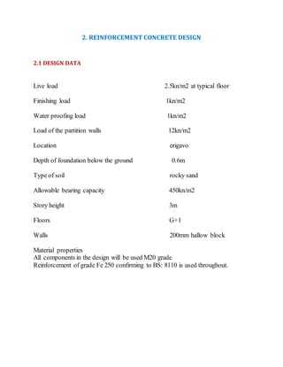
  • 1. 2. REINFORCEMENT CONCRETE DESIGN 2.1 DESIGN DATA Live load 2.5kn/m2 at typical floor Finishing load 1kn/m2 Water proofing load 1kn/m2 Load of the partition walls 12kn/m2 Location erigavo Depth of foundation below the ground 0.6m Type of soil rocky sand Allowable bearing capacity 450kn/m2 Story height 3m Floors G+1 Walls 200mm hallow block Material properties All components in the design will be used M20 grade Reinforcement of grade Fe 250 confirming to BS: 8110 is used throughout.
  • 2. 2.2. Slab design Slabs used in floors and roofsof buildingsmostly integrated with supporting beams that carry the distributed loadsby bending. Slabs have differentshapes, and may be rectangular, squire, circular and many differentirregular shapes dependingof architectural design, so in our design we userectangular shape. Slabs can be designed either oneway or two way slabs dependingon 1. If Ly/Lx<2 the slab is two way where 2. If Ly/Lx>=2 the slab is oneway DATA OF SLAB Characteristic strength of concrete fcu=25N/mm2 Characteristic strength of main reinforcementfy=460 N/mm2 Characteristic strength of links fyv=250 N/mm2 Size of all columns =200 x400(mm) Cover of slab =20 mm Finishing and service = 1.0KN/m2 Live load = 2.5KN/m2 Density of concrete = 24 KN/m3
  • 3. Solution (a)Loadingcalculation Dead loads Self weight of slab = 0.15 x24 =3.6KN/m2 Finishing = 1.0KN/m 2 Total GK= 4.6KN/m2 Imposed load QK =2.5KN/m2 Design ultimate load (N) = (1.4 x4.6 + 1.6 x2.5)= 10.44KN/m2 𝐿𝑦 𝐿𝑥 = 4 4 =1.0 < 2 (two way slab) Mid span (bothway):
  • 4. d= 150-20-10-10/2=115mm Ms= βsnlx2 = 0.024 x10.44x(4)2 = 4.0KNm/m K= M/fcubd2 =4.0 x10⁶/1000 x1152 x35 = 0.009<0.156 Z= d [0.5 + √ 𝑜. 25 − 𝑘/0.9]= 0.99d > 0.95dthereforeapply 0.95d As = M/0.87fyZ= 4.0 x10⁶/0.87x460x 0.95 x 115= 92mm2< Asmin Asmin 0.13%bh0.13/100x1000 x150 =195mm2/m Therefore provideT10-300 c/c(Asprov= 263mm2/m Continuous Edge: d= 150-20-10/2= 125mm Ms= βsnlx2 = 0.032 x10.44x(4)2 = 5.34KNm/m K= M/bd2fcu =5.34 x10⁶/1000 x1252 x35 = 0.0097 < 0.156 Z= d [0.5 + √0.25 − 𝑘/0.9]= 0.99d > 0.95dthereforeapply 0.95d Asmin 0.13%bh0.13/100x1000 x125 =195mm2/m As = M/0.87fyZ= 5.34 x10⁶/0.87x460x125= 107mm2<Asmin Therefore provideT10-300 c/c(Asprov= 263mm2/m) A) Shear check Vs = βvnlx= 0.33 x10.44x4 = 13.8KN/m V= V/bd = 13.8 x10³/1000x125= 0.11KN/mm2
  • 5. 100As/bd = 100 x263/1000 x125 = 0.12 < 3 (satisfactory) 400/d = 400/125=3.2> 1 satisfactory Vc =0.79/1.25 (100As/bd)1/3(400/d)1/4(fcu/25)1/3 Vc =0.79/1.25 (0.21)1/3(3.2)¼(1.4)1/3= 0.56N/mm2> v = 0.15N/mm2 Deflectioncheck (L/d) basic = 26 (L/d)actual =4000/115= 35 M/bd2=5.34 x106/1000x1152 =0.40 fs= 5fy Asreq /8Asprov = 5 x 460 x195 / 8 x 263 = 214 M.F= 0.55+ (477-214/120(0.9+0.40) = 2.23> 2 thereforeuse 2.0 (L/d) allow = 26 x2 =52 (L/d) allow> (L/d) actual (Satisfactory) 2.3. Beam Design Beamsare flexural memberswhich are used to transfer the loads from slab to columnsmay be designed for flexuralmomentin differentfashions depending
  • 6. on the magnitudeof the momentand the dimensions. Accordingly the beam can be singly reinforced, doubly reinforced Tor Lsection. The proceduresand why each is used for specific design type are donebelow. Given data Live load = 2.5 KN/m2 Finishing& service = 1.0 KN/m2 Thickness of slab = 150 mm Fcu = 25 N/mm2 Fy = 460 N/mm2 Fyv = 250 N/mm2 Density of concrete = 24 KN/m3 Size if beam = 250 x450 mm Solution Ly/Lx= 4.2/4.2 = 1.0 < 2 (Two way slab) (a) LoadingCalculation Dead loads
  • 7. Self-weight of slab = 0.15 x24 = 3.6 kN/m2 Finishing + service= = 1.0 kN/m2 Total dead loads, Gk = 4.6 kN/m2 Imposed Load Live load, Qk= 2.5 kN/m2 Thus dead load, Gk = (4.6 x2.5)+ [0.25x(0.45-0.15)x24] = 13.3kN/m Live load, Qk= 2.5 x 2.5 = 6.25 kN/m Design load, w = 1.4Gk+ 1.6Qk = 1.4(13.3)+1.6(6.25) = 28.62 kN/m Load, F = W x L = 28.62 x4.2 = 120 KN
  • 8. Design for main reinforcement Assumeфt = 20mm, фlink = 10mm, cover = 25mm d= h – c - фlink – ½фt = 450 – 25 – 10 – 20/2 = 405mm Mid span of 1-2 and 3-4
  • 9. K= M/fcubd2 =45.4 x10⁶/250 x4052 x25 = 0.044< 0.156(singlyreinforcement) Z= d {0.5 + √0. 25 − 𝑘/0.9]= 0.96d > 0.95d therefore use0.95d As = M/0.87fyZ= 45.4x10⁶/0.87x460x0.95 x405= 295mm2>Asmin Asmin= 0.13%bh= 0.13/100 x450 x250 =146mm2 Asmax = 4%bh = 4/100 x250 x450 = 4500mm2 Use 2T20 (629mm2) Mid span of 2-3 K= M/fcubd2 =35.3 x10⁶/250 x4052 x25 =0.034 < 0.156(singlyreinforcement) Z= d {0.5 + √0. 25 − 𝑘/0.9]= 0.96d > 0.95d therefore use0.95d As = M/0.87fyZ= 35.3x10⁶/0.87x460x0.95 x405= 229mm2>Asmin Asmin= 0.13%bh= 0.13/100 x450 x250 =146mm2 Asmax = 4%bh = 4/100 x250 x450 = 4500mm2 Provide2T20 (629mm2) Support at2-3 K= M/fcubd2 =55.4 x10⁶/250 x4052 x25 =0.053 < 0.156(singlyreinforcement) Z= d {0.5 + √0. 25 − 0.053/0.9]= 0.94d < 0.95d (OK) As = M/0.87fyZ= 55.4x10⁶/0.87x460x0.95 x405= 360mm2>Asmin Asmin= 0.13%bh= 0.13/100 x450 x250 =146mm2 Asmax = 4%bh = 4/100 x250 x450 = 4500mm2 Provide2T16 + 2T16 (As= 804mm) Design for Shear reinforcement
  • 10. At support 2: V= 72.0 KN d= 450 – 25 – 10 – 16 - 2/3(20)/2 = 392mm v = V/bd v = 72.0 x10³/250 x392 = 0.73<0.8√25= 4 kN/mm2 (Ok) V at d = 72 - 0.392(28.62) = 60.7 kN v = V/bd v = 60.7 x10³/250 x392 = 0.62N/mm2 100As /bd = 100(804)/250 x392 = 0.82 < 3 (ok) 400/d = 400/392= 1.02 > 1 (ok) vc= 0.79/1.25(0.82)1/3 (1.02)1/4 = 0.59N/mm2 0.5vc= 0.5 x0.59 = 0.29 N/mm2 vc+ 0.4 = 0.99 N/mm2 Therefore 0.5vc< v < (vc+ 0.4) : - Require minimum shear reinforcement : - provideR10 – 275 c/c At support 1: V= 54.0 KN d= 450 – 25 – 10 – 16 - (20)/2 = 405mm v = V/bd
  • 11. v = 54.0 x10³/250 x392 = 0.53<0.8√25= 4 kN/mm2 (Ok) V at d = 54 – 0.405(28.62) = 52.7 kN v = V/bd v = 52.7 x10³/250 x405 = 0.52N/mm2 100As /bd = 100(629)/250 x405 = 0.62 < 3 (ok) 400/d = 400/405= 0.99 > 1 (Use1) vc= 0.79/1.25(0.62)1/3 (1.0)1/4 = 0.54N/mm2 0.5vc= 0.5 x0.54 = 0.27 N/mm2 vc+ 0.4 = 0.94 N/mm2 Therefore 0.5vc< v < (vc+ 0.4) : - Require minimum shear reinforcement : - provideR10 – 275 c/c Deflectionchecking Checking to be doneat the most critical span, 1-2 and 3-4 M/bd2=45.4 x106/250 x4052= 1.1 fs= 5fy Asreq /8Asprov = 5 x 460 x295 / 8 x 629 = 135
  • 12. Modification factor M.F= 0.55+ (477-135/120(0.9+1.1)= 1.9< 2.0(satisfactory) (L/d) basic = 26 (L/d) allow = 26 x 1.9 = 49.4 (L/d) actual = 4200/405 = 10.4< (L/d) allow The deflection is satisfactory 2.4. Column design Columnsare compression membersthat transfer loads of slabs and any structureabove them to foundation. There are two types of columnswhich are short column and slender column. The followingcondition is determined whether the column is short or slender.
  • 13. If Lex/D <12 and Ley/b <12 The column is short column otherwise it is slender or long column. And also weconsidered that all the loads are axially loaded and there is no eccentricity. Given data fcu=25N/mm2 fy =460N/mm2 Cover = 25mm
  • 14. Solution d = 400 – 25 – 10 – 20/2 = 355 N/bd = 1320 x103/200x400 = 15.37N/mm2 M/bd2= 50 x 106/200 x400 = 1.56N/mm2 From chart fc = 25N/mm2 fy =460N/mm2 100As/bh = 0.7 d/h = 355/400= 0.9 As = (0.7 /100)x200 x35 = 497mm2 Detailing:
  • 15. Use 4T10 (As = 505)SV not morethan 10 ɸ, R6 @ 175 c/c 2.5. Foundation design Foundation issub structurebelow the ground leveland all elements of supper structurestransform all loads and momentsto foundation structureand foundation transformsallloadsto the under layer soil or rock. Thus the foundation structureseffectively supportthesuper structure
  • 16. Given data Column size = 400 x200 mm Dead load = 1000KN Live load = 350KN Soil bearing Capacity = 200 fc = 35 N/mm2 fy = 460N/mm2 Solution 1) Determiningslab thickness, h Use cover 50mm and ɸ of stump = 25mm deformed type2 From table 3.29 la = 27ɸ27x25 = 675 mm Assumethat starting bar is bent 200 mm l = 675 – 200 = 475 mm h = 475 + 50 + 2(25)= 575mm Take h 600 2) Determinefooting area ( serviceability limit state ) GK + QK = 1350 KN Self weight = 10% total = 1350 + 135 = 1485KN Footing area = 1485/200 = 7.84m2 3) Reinforcementdesign ( ultimate limit state ) Design load = 1.4GK+ 1.6 QK = 1.4(1000)+ 1.6 (350) = 1960 KN Soil ultimate pressure = 1960/7.84= 250KN/m2
  • 17. Moment= 250 x1000 x1.2 x 1.2/2 = 225 KNm Becauseof it is a square footing, design for critical d only Assume ɸ= 20mm d = h-c-ɸ-ɸ/2 = 600-50 -20 -20/2 = 520mm NOTE: Take the lesser `d` on onedirection as critical d = 500-50-12-12/2= 432mm K = M/bd2fcu = 225 x106/1000x5202 x35 = 0.023 < 0.156 Z = d [0.5√0.25− 0.023/0.9] = 0.97d > 0.95d∴ 𝑢𝑠𝑒 0.95𝑑 Asreq = 504 x106/0.87 x460 x0.95520= 2549mm2 Check Asmin = 0.13/100 x1000x600 = 2166mm2< Asreq(Ok) So use Asreq.
  • 18. Provide9T20 (Asreq=2826mm2) Check cracking Allowable distance between bar = 3d @ 375mm (lesser) 3d = 3 x 520 = 1560mm > 375mm ∴Allowable distance = 750mm Actual distance between bar = {1000-2(50)-9(20)}/8 = 90mm < 375mm(ok). h>200mm ∴need further checking Check 100A /bd = 0.14 < 0.3 ∴no furtherchecking required Detailing ly = lx = 1000mm 1.5 (ly+ 3d)= 1.5(lx+3d)= 1.5 (400 + 3 x520)= 2940mm L = 1000 > 1.5 (c+3d)so reinforcementsdistribution isuniform. 2.6. Staircase design Staircase is an importantcomponentof buildingprovidingaccess to different floorsand roofs of the building. it consist of a flight of steps(stairs) and one or moreintermediate landingslabs between the floor levels. Given data : Fcu = 30 N/mm2 Fy= 460 N/mm2 Riser(R) = 175mm Going(G) = 250mm Live load =5kn/m2
  • 19. Finishing = 0.4kn/m2 Solution a) Assumingthe thickness of waist Becausespan is simply supported chooseL/d = 24 (No additionalfactor for L/d because stairs span is less than 60% of total span) d= 6350/24= 265 , assumeф = 16 and cover = 20mm :- therefore h = 263+(16/2)+20= 293 mm Hence take h = 300mm and d = 300-(16/2)-20 = 272mm b) Loading( on plan view): i. Stairs: Dead load : waist = 0.3 x 1.22 x24 = 8.8 KN/m2
  • 20. Stair = (0.175/2)x24 = 2.1 kN/m2 Finishing = 0.4 kN/m2 Total Gk = 11.3kN/m2 Imposed load Qk = 5.0 kN/m2 :- Designload = 1.4(11.3)+ 1.6(5.0)= 23.8kN/m2 ii. Landing: Dead load: waist = 0.3 x 24 = 7.2 kN.m2 Finishing = 0.4 kN/m2 Total Gk = 7.6 kN/m2 :- Design load = 1.4(7.6)+ 1.6(5.0)= 18.6kN/m2 ∑ M cutting = 0 ; M max –(18.6 x1.5 x2.425) – (23.8 x1.6752 x/2 ) + 67.8(3.175)= 0 :- M max= 114 kN/m width
  • 21. K= M/fcubd2 = 114 x106 / 1000 x2722 x30 = 0.051 < 0.156 Z = d [0.5 + √0.25 − 0.051/0.9] = 0.94d < 0.95d (ok) As = 114 x106 / 0.87 x460 x0.94 x272 = 1114 mm2/m ProvideT16 – 175 c/c (Asprovide = 1150 mm2/m) Reinforcementdistribution, useAsmin = 0.13%bh = 0.13/100 x (1000)(300) =390 mm2/m. Deflectionchecking M/bd2 = 114 x106/1000 x2722 = 2.40 fs= 5 x 460 x1114 /8 x1150 = 278 M.F= 0.55 + (477-278)/120(0.9 + 2.40)= 1.7 (l/d) allowable = 20 x .07 = 34.00 (l/d) actual = 6350/272 = 23 < 34 ( Ok )