SlideShare a Scribd company logo
1 of 6
Download to read offline
ABSTRACT 
Here, design of a power screw driven press is to be discussed. As usual design considerations 
include more than one unknowns therefore an engineer’s problems usually do not seems two 
unknowns, two equations. But still design should be done, in this aspect I will centre on my 
design approach to the screws with regarding safety and then select the nut and motor for this 
specific purpose. 
3 
CONTENTS 
Abstract II 
1.Introductin 3 
2.Design Analysis 
2.1 Design Terminology for Power Screws 3 
2.2 Design of screw and nut 5 
2.1.1 Screw diameter selection 5 
2.1.2 Nut height selection 5 
2.3 Buckling consideration 6 
2.4 Self-locking condition 6 
2.5 Torque calculation 6 
2.6 Efficiency 7 
2.7 Motor selection 7 
3.Conclusion and Future Developments 7 
References 7 
Appendix
1. INTRODUCTION 
I will initialize my design by selecting a screw that is available for me (say in the foundation) 
and then check it for safety if satisfied or not. And later on consideration of self locking 
condition, efficiency and required power input according to the selected screw is going to be 
done for the understanding of practicalability to life. Finally a nut for the screw is selected by 
regarding bearing and shear stresses. 
4 
2. DESIGN ANALYSIS 
Fig 1. 
A schematic example of application of power screws to a power driven press is shown in 
figure 1. The some of the desired properties are tabulated as below. By using this table the 
screw, nut and motor for our pressing operation is going to be selected from standard tables or 
in other words from machineries catalogue. 
As seen from the figure 1. , pressing operation is the reverse organization of raising a load so 
our job is again as in the raising. This is important in order not to confuse lowering or rising.
5 
Screw pitch, p(mm) 6 
Screw threads Triple 
Factor of safety, n 3 
Load per screw , F(tons) 4 
Friction coefficient, μ 0,22 
Motor speed, n(rpm) 800 
Material of screw 080M50CD 
Screw Ultimate Strength, Sut (MPa) 650 
Screw Yield Strength, Sy(MPa) 510 
Screw Modulus of elasticity, E (GPa) 207 
Material of nut ASTM Gray Cast Iron 
Nut Ultimate Strength, Suc (MPa) 670 
Nut Yield Strength, Sy(MPa) 220 
Table 1. 
2.1 Design Terminology for Power Screws 
A power screw of outside diameter, do, is designed to have a thread pitch, p. The application 
of the device requires the screw to lift or lower the load. (in our case press the load which is 
in the same manner as lifting the load). The coefficient of friction for the thread is μt and 
for the collar μc (in our case collar is not used so no collar friction exists). 
Fig2. 
Unwrapping one thread the following wedge geometry results: 
Where >= Lead angle, 
L=Lead, 
Dm=mean diameter of the contact, 
For a single threaded screw L is the same as the pitch but for double or triple threaded screws 
L is equal to pitch times number of thread for one rotation of screw. (in our case a triple 
threaded screw is used)
6 
Fig 3. 
2.2 Design of screw and nut, 
2.2.1 Screw diameter selection, 
From table 1. a screw which is triple threaded and having a 6 mm pitch exists. Since the 
diameter of the screw is needed for our calculations, selecting a metric screw having, p=6 and 
going on my calculation will not be wrong unless the screw I selected does not ensure the 
safety concern. 
Our possible choice of diameters for a metric grade 6mm pitch are, 64, 72, 80, 90, 100 for 
coarse-pitch series. Let’s start our design with M 64.6 . 
Calculations according to M64.6 screw; 
mean diameter, dm=d – p/2 = 64 – 6/2 =61 mm, 
pitch, p=6 mm, 
Lead, L=3*6=18 mm, 
F=mg=4000*9.81=40 kN(approximately), 
F(load factor of sfety included)=F*n=40*4= 160 kN, 
Now check the strength of the screw in order to be sure that we are on the safe side wrt n=4; 
650 
 
 = = = MPa 
10.88 
Fn 
160000 
c 59.7 
At 
2680 
u 
= = = 
59,7 
c 
n 
 
which is safer than desired. 
Note: If we don’t have to use a 6mm pitch screw with respect to standards a smaller diameter 
screw will be enough for strenght consideration. 
So we can continue our design with M64.6 screw . 
2.2.2 Nut height selection, 
Check shearing of threads for h, 
Fn 
dh 
s 
 
 
2 
= s = Ssy = 0.5Sy = 0.5*510 = 255MPa h=6.88 mm 
Check shearing of nut for h, 
Fn 
drh 
s 
 
 
2 
= h=7.98 mm, 
Check bearing stress of nut for h,
compareb with Suc, since we have already included factor of safety n 
7 
4 
pFn 
h d 2 dr 
2 ( ) 
b 
− 
= 
 
by rising force. 
4 
pFn 
2 2 Suc d dr 
( ) 
h 
− 
= 
 
h=2.49 mm 
After these calculations we can decide h for our nut as 8 mm wrt shearing of nut . 
2.3 Buckling consideration 
Now we should consider buckling for designing the length of the screw. 
Since we don’t know the column is either Euler’s or Johnson’s, we need to make an 
assumption. Since the loading is axial my suggestion is Euler’s column. 
4 
 
* 
Inertia, 4 
555497.2 
64 
mm 
dr 
I = = 
C is equal to 0.25 since our situation best fits one end fixed and one end free. 
2 
C EI 
Critical laod, 2 
L 
Pcr 
 
= 
If we equalize Pcr to F*n, then we will get the maximum available length of the screw . 
When n=4 and E=207GPa from table 1.; L=1331 mm 
Select L= 1m for our case will give Pcr=283.7kN ; 
Compare the applied load and the critical load in order to prevent buckling, 
Pcr=283.7kN F= 40kN . But now there is one more step which is cheking our 
assumption; 
44.75 
2 2 
CE 
L  
= =  
1 


Sy 
k 
62.5 
4 
= L 
= 
D 
L 
k 


L 
L 
Check if  


k 
k 
1 
44.75  62.5, Therefore our assumption is correct. 
Designing our screw length as 1 meter will be safe for buckling. 
2.4 Self-locking condition, 
The condition for self locking is μ  tan
 or 
L 
 
μ  let’s compare, 
dm 
0.22 0.09 therfore self-locking condition is established for our situation. 
2.5 Torque calculation 
After completing screw design, we can calculate the required torque(raising load) for 
pressing operation. 
 
 μ 
* 


* * 
* 
F dm L dm 
− 
+ 
= 
dm L 
Tr 
 μ 
2 
when we put the values into eqaution from table 1 and 
use M64.6 screw; Tr =1564,3 Nm =1,565 kNm
8 
2.6 Efficiency 
0.292 
FL 
To 
= = = 
2 
Tr 
T 
e 
 
=29.2% Our design has an efficiency of 29.2 percent 
2.7 Motor selection 
Since there exists a gear ratio of 4 between motor and screw head gear, the velocity ratio will 
also be 4. From table 1. the motor’s angular velocity is suggested as 800 rpm so we can 
calculate screw velocity w as; 
Wscrew=800/4=200 rpm 200rpm=200*2A/60 =20.94 rad/sec. 
Power=T*w=1.565 * 21 = 32.865 kw 32.865kw=32.865/0.745=44 hp 
So a 45 hp G.E (50 hertz) Electric motor, 400/440 volt, 725 rpm or 50 hp G.G.E Electric 
motor, 460 volt, 1170 rpm may be suggested for our design. 
We have concluded our power screw driven press design by using a M64.6 grade screw 
in length of 1 meter , a 8mm in height nut and a 45 hp electic motor. 
3.CONCLUSIONS AND FUTURE IMPROVEMENTS 
We have started our design by assumptions and then realized them step by step and ensured 
safety by using standardized screws, nuts and selecting a widely used electric motor. As seen 
our way of solution design is not a straight forward problem but needs engineering judgement. 
After mechanical design analysis a further step should be cost analysis in order to say; our 
design is just ready for manufacturing. 
REFERENCES 
1. J.Hüseyin Filiz. Problems on the design of machine elements. 
2. Joseph E.Shigley, Charles R.Mischke, Richard G.Budynas (7th edition). Mechanical 
Engineering design. 
3. www.FlyPress.com 
4. www.Savonaequip.com

More Related Content

What's hot

Unit 2 Design Of Shafts Keys and Couplings
Unit 2 Design Of Shafts Keys and CouplingsUnit 2 Design Of Shafts Keys and Couplings
Unit 2 Design Of Shafts Keys and CouplingsMahesh Shinde
 
TAMU MEEN 475 Group D Presentation F2017
TAMU MEEN 475 Group D Presentation F2017TAMU MEEN 475 Group D Presentation F2017
TAMU MEEN 475 Group D Presentation F2017Miguel Rico, EIT
 
Unit 4 Design of Power Screw and Screw Jack
Unit 4 Design of Power Screw and Screw JackUnit 4 Design of Power Screw and Screw Jack
Unit 4 Design of Power Screw and Screw JackMahesh Shinde
 
Design of shaft couplings
Design of shaft couplingsDesign of shaft couplings
Design of shaft couplingsmishini anil
 
Design and analysis of connecting rod using aluminium alloy 7068 t6 t6511
Design and analysis of connecting rod using aluminium alloy 7068 t6 t6511Design and analysis of connecting rod using aluminium alloy 7068 t6 t6511
Design and analysis of connecting rod using aluminium alloy 7068 t6 t6511IAEME Publication
 
Design & Construction of a Connecting rod
Design & Construction of a Connecting rodDesign & Construction of a Connecting rod
Design & Construction of a Connecting rodFaisal Niloy
 
Desing of flange coupling
Desing of flange couplingDesing of flange coupling
Desing of flange couplingTushar Pillai
 
Mechanical Engineering Standard Design Data Book
Mechanical Engineering Standard Design Data BookMechanical Engineering Standard Design Data Book
Mechanical Engineering Standard Design Data BookHiten Bhadja
 
design of screw jac k may 2020
design of screw jac k may 2020design of screw jac k may 2020
design of screw jac k may 2020Gaurav Mistry
 
Shafts and Shafts Components
Shafts and Shafts ComponentsShafts and Shafts Components
Shafts and Shafts ComponentsV-Motech
 
design of knuckle joint may 2020
design of knuckle joint may 2020design of knuckle joint may 2020
design of knuckle joint may 2020Gaurav Mistry
 
Analytical study of connecting rods
Analytical study of connecting rodsAnalytical study of connecting rods
Analytical study of connecting rodsFaisal Bin Faruk
 
Coupling and flange coupling and its design
Coupling and flange coupling and its designCoupling and flange coupling and its design
Coupling and flange coupling and its designRupesh Kumar
 

What's hot (20)

Shaft loding
Shaft lodingShaft loding
Shaft loding
 
Ijariie1189
Ijariie1189Ijariie1189
Ijariie1189
 
Unit 2 Design Of Shafts Keys and Couplings
Unit 2 Design Of Shafts Keys and CouplingsUnit 2 Design Of Shafts Keys and Couplings
Unit 2 Design Of Shafts Keys and Couplings
 
TAMU MEEN 475 Group D Presentation F2017
TAMU MEEN 475 Group D Presentation F2017TAMU MEEN 475 Group D Presentation F2017
TAMU MEEN 475 Group D Presentation F2017
 
Unit 4 Design of Power Screw and Screw Jack
Unit 4 Design of Power Screw and Screw JackUnit 4 Design of Power Screw and Screw Jack
Unit 4 Design of Power Screw and Screw Jack
 
Design of shaft couplings
Design of shaft couplingsDesign of shaft couplings
Design of shaft couplings
 
Knuckle joint silde
Knuckle joint sildeKnuckle joint silde
Knuckle joint silde
 
Unit 3.1 Design of Shaft
Unit 3.1 Design of ShaftUnit 3.1 Design of Shaft
Unit 3.1 Design of Shaft
 
Design and analysis of connecting rod using aluminium alloy 7068 t6 t6511
Design and analysis of connecting rod using aluminium alloy 7068 t6 t6511Design and analysis of connecting rod using aluminium alloy 7068 t6 t6511
Design and analysis of connecting rod using aluminium alloy 7068 t6 t6511
 
Ch 8 slides_m
Ch 8 slides_mCh 8 slides_m
Ch 8 slides_m
 
Design & Construction of a Connecting rod
Design & Construction of a Connecting rodDesign & Construction of a Connecting rod
Design & Construction of a Connecting rod
 
Unit 5 threaded joint
Unit 5 threaded jointUnit 5 threaded joint
Unit 5 threaded joint
 
Desing of flange coupling
Desing of flange couplingDesing of flange coupling
Desing of flange coupling
 
Mechanical Engineering Standard Design Data Book
Mechanical Engineering Standard Design Data BookMechanical Engineering Standard Design Data Book
Mechanical Engineering Standard Design Data Book
 
design of screw jac k may 2020
design of screw jac k may 2020design of screw jac k may 2020
design of screw jac k may 2020
 
Shafts and Shafts Components
Shafts and Shafts ComponentsShafts and Shafts Components
Shafts and Shafts Components
 
design of knuckle joint may 2020
design of knuckle joint may 2020design of knuckle joint may 2020
design of knuckle joint may 2020
 
Analytical study of connecting rods
Analytical study of connecting rodsAnalytical study of connecting rods
Analytical study of connecting rods
 
Coupling and flange coupling and its design
Coupling and flange coupling and its designCoupling and flange coupling and its design
Coupling and flange coupling and its design
 
Design of toggle jack
Design of toggle jackDesign of toggle jack
Design of toggle jack
 

Similar to Power screw Erdi Karaçal Mechanical Engineer University of Gaziantep

Design mini-project for TY mechanical students
Design mini-project for TY mechanical studentsDesign mini-project for TY mechanical students
Design mini-project for TY mechanical studentsRavindra Shinde
 
Universal Testing Machine
Universal Testing MachineUniversal Testing Machine
Universal Testing MachineAshish Kholia
 
Design of a Multispeed Multistage Gearbox
Design of a Multispeed Multistage GearboxDesign of a Multispeed Multistage Gearbox
Design of a Multispeed Multistage GearboxIJERA Editor
 
Shaft design Erdi Karaçal Mechanical Engineer University of Gaziantep
Shaft design Erdi Karaçal Mechanical Engineer University of GaziantepShaft design Erdi Karaçal Mechanical Engineer University of Gaziantep
Shaft design Erdi Karaçal Mechanical Engineer University of GaziantepErdi Karaçal
 
Design and Construction of a Connecting rod
Design and Construction of a Connecting rodDesign and Construction of a Connecting rod
Design and Construction of a Connecting rodFaisal Niloy
 
Valves analysis case study (2)
Valves analysis case study (2)Valves analysis case study (2)
Valves analysis case study (2)shijovadakkan
 
ANALYSIS OF KNUCKLE JOINT
ANALYSIS OF KNUCKLE JOINTANALYSIS OF KNUCKLE JOINT
ANALYSIS OF KNUCKLE JOINTOmkar Kamodkar
 
Static Strain Measurement (Over Hanging Beam).pptx
Static Strain Measurement (Over Hanging Beam).pptxStatic Strain Measurement (Over Hanging Beam).pptx
Static Strain Measurement (Over Hanging Beam).pptxAshok Banagar
 
Spur gear problem and solution
Spur gear   problem and solutionSpur gear   problem and solution
Spur gear problem and solutiondodi mulya
 
Design of Simple Machine Parts
Design of Simple Machine PartsDesign of Simple Machine Parts
Design of Simple Machine PartsMahesh Shinde
 
Strength Analysis and Optimization Design about the key parts of the Robot
Strength Analysis and Optimization Design about the key parts of the RobotStrength Analysis and Optimization Design about the key parts of the Robot
Strength Analysis and Optimization Design about the key parts of the RobotIJRES Journal
 

Similar to Power screw Erdi Karaçal Mechanical Engineer University of Gaziantep (20)

Design mini-project for TY mechanical students
Design mini-project for TY mechanical studentsDesign mini-project for TY mechanical students
Design mini-project for TY mechanical students
 
Universal Testing Machine
Universal Testing MachineUniversal Testing Machine
Universal Testing Machine
 
Design of a Multispeed Multistage Gearbox
Design of a Multispeed Multistage GearboxDesign of a Multispeed Multistage Gearbox
Design of a Multispeed Multistage Gearbox
 
Shaft design Erdi Karaçal Mechanical Engineer University of Gaziantep
Shaft design Erdi Karaçal Mechanical Engineer University of GaziantepShaft design Erdi Karaçal Mechanical Engineer University of Gaziantep
Shaft design Erdi Karaçal Mechanical Engineer University of Gaziantep
 
Final year project
Final year projectFinal year project
Final year project
 
connecting rod
connecting rodconnecting rod
connecting rod
 
[IJET-V1I2P4] Authors :Mrs.Rita S. Pimpalkar, Rutuja U. Joshi, Rakesh R. Khan...
[IJET-V1I2P4] Authors :Mrs.Rita S. Pimpalkar, Rutuja U. Joshi, Rakesh R. Khan...[IJET-V1I2P4] Authors :Mrs.Rita S. Pimpalkar, Rutuja U. Joshi, Rakesh R. Khan...
[IJET-V1I2P4] Authors :Mrs.Rita S. Pimpalkar, Rutuja U. Joshi, Rakesh R. Khan...
 
Design and Construction of a Connecting rod
Design and Construction of a Connecting rodDesign and Construction of a Connecting rod
Design and Construction of a Connecting rod
 
Staircase Design Report
Staircase Design ReportStaircase Design Report
Staircase Design Report
 
Modeling and fem analysis of knuckle joint
Modeling and fem analysis of knuckle jointModeling and fem analysis of knuckle joint
Modeling and fem analysis of knuckle joint
 
Valves analysis case study (2)
Valves analysis case study (2)Valves analysis case study (2)
Valves analysis case study (2)
 
ANALYSIS OF KNUCKLE JOINT
ANALYSIS OF KNUCKLE JOINTANALYSIS OF KNUCKLE JOINT
ANALYSIS OF KNUCKLE JOINT
 
Gearbox design
Gearbox designGearbox design
Gearbox design
 
M1
M1M1
M1
 
Static Strain Measurement (Over Hanging Beam).pptx
Static Strain Measurement (Over Hanging Beam).pptxStatic Strain Measurement (Over Hanging Beam).pptx
Static Strain Measurement (Over Hanging Beam).pptx
 
Spur gear problem and solution
Spur gear   problem and solutionSpur gear   problem and solution
Spur gear problem and solution
 
3. v belt and sample problem
3. v belt and sample problem3. v belt and sample problem
3. v belt and sample problem
 
3. v belt and sample problem
3. v belt and sample problem3. v belt and sample problem
3. v belt and sample problem
 
Design of Simple Machine Parts
Design of Simple Machine PartsDesign of Simple Machine Parts
Design of Simple Machine Parts
 
Strength Analysis and Optimization Design about the key parts of the Robot
Strength Analysis and Optimization Design about the key parts of the RobotStrength Analysis and Optimization Design about the key parts of the Robot
Strength Analysis and Optimization Design about the key parts of the Robot
 

More from Erdi Karaçal

Ch40 design selection
Ch40 design selectionCh40 design selection
Ch40 design selectionErdi Karaçal
 
Ch39 computer aided manufacturing
Ch39 computer aided manufacturingCh39 computer aided manufacturing
Ch39 computer aided manufacturingErdi Karaçal
 
Ch33 surface roughness
Ch33 surface roughnessCh33 surface roughness
Ch33 surface roughnessErdi Karaçal
 
Ch32 brazing soldering
Ch32 brazing solderingCh32 brazing soldering
Ch32 brazing solderingErdi Karaçal
 
Ch31 solid state welding Erdi Karaçal Mechanical Engineer University of Gazia...
Ch31 solid state welding Erdi Karaçal Mechanical Engineer University of Gazia...Ch31 solid state welding Erdi Karaçal Mechanical Engineer University of Gazia...
Ch31 solid state welding Erdi Karaçal Mechanical Engineer University of Gazia...Erdi Karaçal
 
Ch30 fusion welding Erdi Karaçal Mechanical Engineer University of Gaziantep
Ch30 fusion welding Erdi Karaçal Mechanical Engineer University of GaziantepCh30 fusion welding Erdi Karaçal Mechanical Engineer University of Gaziantep
Ch30 fusion welding Erdi Karaçal Mechanical Engineer University of GaziantepErdi Karaçal
 
Ch29 microeletrical fabrication Erdi Karaçal Mechanical Engineer University o...
Ch29 microeletrical fabrication Erdi Karaçal Mechanical Engineer University o...Ch29 microeletrical fabrication Erdi Karaçal Mechanical Engineer University o...
Ch29 microeletrical fabrication Erdi Karaçal Mechanical Engineer University o...Erdi Karaçal
 
Ch28 microelectronic devices Erdi Karaçal Mechanical Engineer University of G...
Ch28 microelectronic devices Erdi Karaçal Mechanical Engineer University of G...Ch28 microelectronic devices Erdi Karaçal Mechanical Engineer University of G...
Ch28 microelectronic devices Erdi Karaçal Mechanical Engineer University of G...Erdi Karaçal
 
Ch27 advanced machining Erdi Karaçal Mechanical Engineer University of Gaziantep
Ch27 advanced machining Erdi Karaçal Mechanical Engineer University of GaziantepCh27 advanced machining Erdi Karaçal Mechanical Engineer University of Gaziantep
Ch27 advanced machining Erdi Karaçal Mechanical Engineer University of GaziantepErdi Karaçal
 
Ch26 abrassive machining Erdi Karaçal Mechanical Engineer University of Gazia...
Ch26 abrassive machining Erdi Karaçal Mechanical Engineer University of Gazia...Ch26 abrassive machining Erdi Karaçal Mechanical Engineer University of Gazia...
Ch26 abrassive machining Erdi Karaçal Mechanical Engineer University of Gazia...Erdi Karaçal
 
Ch25 machining centers Erdi Karaçal Mechanical Engineer University of Gaziantep
Ch25 machining centers Erdi Karaçal Mechanical Engineer University of GaziantepCh25 machining centers Erdi Karaçal Mechanical Engineer University of Gaziantep
Ch25 machining centers Erdi Karaçal Mechanical Engineer University of GaziantepErdi Karaçal
 
Ch24 milling Erdi Karaçal Mechanical Engineer University of Gaziantep
Ch24 milling Erdi Karaçal Mechanical Engineer University of GaziantepCh24 milling Erdi Karaçal Mechanical Engineer University of Gaziantep
Ch24 milling Erdi Karaçal Mechanical Engineer University of GaziantepErdi Karaçal
 

More from Erdi Karaçal (20)

afm of Ti6Al4V
afm of Ti6Al4V afm of Ti6Al4V
afm of Ti6Al4V
 
Met ch1
Met ch1Met ch1
Met ch1
 
Met ch0
Met ch0Met ch0
Met ch0
 
Ch40 design selection
Ch40 design selectionCh40 design selection
Ch40 design selection
 
Ch39 computer aided manufacturing
Ch39 computer aided manufacturingCh39 computer aided manufacturing
Ch39 computer aided manufacturing
 
Ch38 computer aided
Ch38 computer aidedCh38 computer aided
Ch38 computer aided
 
Ch37 automation
Ch37 automationCh37 automation
Ch37 automation
 
Ch36 quality
Ch36 qualityCh36 quality
Ch36 quality
 
Ch35 measurement
Ch35 measurementCh35 measurement
Ch35 measurement
 
Ch34 coating
Ch34 coatingCh34 coating
Ch34 coating
 
Ch33 surface roughness
Ch33 surface roughnessCh33 surface roughness
Ch33 surface roughness
 
Ch32 brazing soldering
Ch32 brazing solderingCh32 brazing soldering
Ch32 brazing soldering
 
Ch31 solid state welding Erdi Karaçal Mechanical Engineer University of Gazia...
Ch31 solid state welding Erdi Karaçal Mechanical Engineer University of Gazia...Ch31 solid state welding Erdi Karaçal Mechanical Engineer University of Gazia...
Ch31 solid state welding Erdi Karaçal Mechanical Engineer University of Gazia...
 
Ch30 fusion welding Erdi Karaçal Mechanical Engineer University of Gaziantep
Ch30 fusion welding Erdi Karaçal Mechanical Engineer University of GaziantepCh30 fusion welding Erdi Karaçal Mechanical Engineer University of Gaziantep
Ch30 fusion welding Erdi Karaçal Mechanical Engineer University of Gaziantep
 
Ch29 microeletrical fabrication Erdi Karaçal Mechanical Engineer University o...
Ch29 microeletrical fabrication Erdi Karaçal Mechanical Engineer University o...Ch29 microeletrical fabrication Erdi Karaçal Mechanical Engineer University o...
Ch29 microeletrical fabrication Erdi Karaçal Mechanical Engineer University o...
 
Ch28 microelectronic devices Erdi Karaçal Mechanical Engineer University of G...
Ch28 microelectronic devices Erdi Karaçal Mechanical Engineer University of G...Ch28 microelectronic devices Erdi Karaçal Mechanical Engineer University of G...
Ch28 microelectronic devices Erdi Karaçal Mechanical Engineer University of G...
 
Ch27 advanced machining Erdi Karaçal Mechanical Engineer University of Gaziantep
Ch27 advanced machining Erdi Karaçal Mechanical Engineer University of GaziantepCh27 advanced machining Erdi Karaçal Mechanical Engineer University of Gaziantep
Ch27 advanced machining Erdi Karaçal Mechanical Engineer University of Gaziantep
 
Ch26 abrassive machining Erdi Karaçal Mechanical Engineer University of Gazia...
Ch26 abrassive machining Erdi Karaçal Mechanical Engineer University of Gazia...Ch26 abrassive machining Erdi Karaçal Mechanical Engineer University of Gazia...
Ch26 abrassive machining Erdi Karaçal Mechanical Engineer University of Gazia...
 
Ch25 machining centers Erdi Karaçal Mechanical Engineer University of Gaziantep
Ch25 machining centers Erdi Karaçal Mechanical Engineer University of GaziantepCh25 machining centers Erdi Karaçal Mechanical Engineer University of Gaziantep
Ch25 machining centers Erdi Karaçal Mechanical Engineer University of Gaziantep
 
Ch24 milling Erdi Karaçal Mechanical Engineer University of Gaziantep
Ch24 milling Erdi Karaçal Mechanical Engineer University of GaziantepCh24 milling Erdi Karaçal Mechanical Engineer University of Gaziantep
Ch24 milling Erdi Karaçal Mechanical Engineer University of Gaziantep
 

Recently uploaded

Input Output Management in Operating System
Input Output Management in Operating SystemInput Output Management in Operating System
Input Output Management in Operating SystemRashmi Bhat
 
An experimental study in using natural admixture as an alternative for chemic...
An experimental study in using natural admixture as an alternative for chemic...An experimental study in using natural admixture as an alternative for chemic...
An experimental study in using natural admixture as an alternative for chemic...Chandu841456
 
home automation using Arduino by Aditya Prasad
home automation using Arduino by Aditya Prasadhome automation using Arduino by Aditya Prasad
home automation using Arduino by Aditya Prasadaditya806802
 
Gurgaon ✡️9711147426✨Call In girls Gurgaon Sector 51 escort service
Gurgaon ✡️9711147426✨Call In girls Gurgaon Sector 51 escort serviceGurgaon ✡️9711147426✨Call In girls Gurgaon Sector 51 escort service
Gurgaon ✡️9711147426✨Call In girls Gurgaon Sector 51 escort servicejennyeacort
 
Mine Environment II Lab_MI10448MI__________.pptx
Mine Environment II Lab_MI10448MI__________.pptxMine Environment II Lab_MI10448MI__________.pptx
Mine Environment II Lab_MI10448MI__________.pptxRomil Mishra
 
THE SENDAI FRAMEWORK FOR DISASTER RISK REDUCTION
THE SENDAI FRAMEWORK FOR DISASTER RISK REDUCTIONTHE SENDAI FRAMEWORK FOR DISASTER RISK REDUCTION
THE SENDAI FRAMEWORK FOR DISASTER RISK REDUCTIONjhunlian
 
Instrumentation, measurement and control of bio process parameters ( Temperat...
Instrumentation, measurement and control of bio process parameters ( Temperat...Instrumentation, measurement and control of bio process parameters ( Temperat...
Instrumentation, measurement and control of bio process parameters ( Temperat...121011101441
 
Risk Assessment For Installation of Drainage Pipes.pdf
Risk Assessment For Installation of Drainage Pipes.pdfRisk Assessment For Installation of Drainage Pipes.pdf
Risk Assessment For Installation of Drainage Pipes.pdfROCENODodongVILLACER
 
Industrial Safety Unit-I SAFETY TERMINOLOGIES
Industrial Safety Unit-I SAFETY TERMINOLOGIESIndustrial Safety Unit-I SAFETY TERMINOLOGIES
Industrial Safety Unit-I SAFETY TERMINOLOGIESNarmatha D
 
Why does (not) Kafka need fsync: Eliminating tail latency spikes caused by fsync
Why does (not) Kafka need fsync: Eliminating tail latency spikes caused by fsyncWhy does (not) Kafka need fsync: Eliminating tail latency spikes caused by fsync
Why does (not) Kafka need fsync: Eliminating tail latency spikes caused by fsyncssuser2ae721
 
Introduction to Machine Learning Unit-3 for II MECH
Introduction to Machine Learning Unit-3 for II MECHIntroduction to Machine Learning Unit-3 for II MECH
Introduction to Machine Learning Unit-3 for II MECHC Sai Kiran
 
Sachpazis Costas: Geotechnical Engineering: A student's Perspective Introduction
Sachpazis Costas: Geotechnical Engineering: A student's Perspective IntroductionSachpazis Costas: Geotechnical Engineering: A student's Perspective Introduction
Sachpazis Costas: Geotechnical Engineering: A student's Perspective IntroductionDr.Costas Sachpazis
 
Solving The Right Triangles PowerPoint 2.ppt
Solving The Right Triangles PowerPoint 2.pptSolving The Right Triangles PowerPoint 2.ppt
Solving The Right Triangles PowerPoint 2.pptJasonTagapanGulla
 
CCS355 Neural Networks & Deep Learning Unit 1 PDF notes with Question bank .pdf
CCS355 Neural Networks & Deep Learning Unit 1 PDF notes with Question bank .pdfCCS355 Neural Networks & Deep Learning Unit 1 PDF notes with Question bank .pdf
CCS355 Neural Networks & Deep Learning Unit 1 PDF notes with Question bank .pdfAsst.prof M.Gokilavani
 
Unit7-DC_Motors nkkjnsdkfnfcdfknfdgfggfg
Unit7-DC_Motors nkkjnsdkfnfcdfknfdgfggfgUnit7-DC_Motors nkkjnsdkfnfcdfknfdgfggfg
Unit7-DC_Motors nkkjnsdkfnfcdfknfdgfggfgsaravananr517913
 
Correctly Loading Incremental Data at Scale
Correctly Loading Incremental Data at ScaleCorrectly Loading Incremental Data at Scale
Correctly Loading Incremental Data at ScaleAlluxio, Inc.
 
Software and Systems Engineering Standards: Verification and Validation of Sy...
Software and Systems Engineering Standards: Verification and Validation of Sy...Software and Systems Engineering Standards: Verification and Validation of Sy...
Software and Systems Engineering Standards: Verification and Validation of Sy...VICTOR MAESTRE RAMIREZ
 
Work Experience-Dalton Park.pptxfvvvvvvv
Work Experience-Dalton Park.pptxfvvvvvvvWork Experience-Dalton Park.pptxfvvvvvvv
Work Experience-Dalton Park.pptxfvvvvvvvLewisJB
 
Concrete Mix Design - IS 10262-2019 - .pptx
Concrete Mix Design - IS 10262-2019 - .pptxConcrete Mix Design - IS 10262-2019 - .pptx
Concrete Mix Design - IS 10262-2019 - .pptxKartikeyaDwivedi3
 

Recently uploaded (20)

Input Output Management in Operating System
Input Output Management in Operating SystemInput Output Management in Operating System
Input Output Management in Operating System
 
An experimental study in using natural admixture as an alternative for chemic...
An experimental study in using natural admixture as an alternative for chemic...An experimental study in using natural admixture as an alternative for chemic...
An experimental study in using natural admixture as an alternative for chemic...
 
home automation using Arduino by Aditya Prasad
home automation using Arduino by Aditya Prasadhome automation using Arduino by Aditya Prasad
home automation using Arduino by Aditya Prasad
 
Gurgaon ✡️9711147426✨Call In girls Gurgaon Sector 51 escort service
Gurgaon ✡️9711147426✨Call In girls Gurgaon Sector 51 escort serviceGurgaon ✡️9711147426✨Call In girls Gurgaon Sector 51 escort service
Gurgaon ✡️9711147426✨Call In girls Gurgaon Sector 51 escort service
 
Mine Environment II Lab_MI10448MI__________.pptx
Mine Environment II Lab_MI10448MI__________.pptxMine Environment II Lab_MI10448MI__________.pptx
Mine Environment II Lab_MI10448MI__________.pptx
 
THE SENDAI FRAMEWORK FOR DISASTER RISK REDUCTION
THE SENDAI FRAMEWORK FOR DISASTER RISK REDUCTIONTHE SENDAI FRAMEWORK FOR DISASTER RISK REDUCTION
THE SENDAI FRAMEWORK FOR DISASTER RISK REDUCTION
 
Instrumentation, measurement and control of bio process parameters ( Temperat...
Instrumentation, measurement and control of bio process parameters ( Temperat...Instrumentation, measurement and control of bio process parameters ( Temperat...
Instrumentation, measurement and control of bio process parameters ( Temperat...
 
Risk Assessment For Installation of Drainage Pipes.pdf
Risk Assessment For Installation of Drainage Pipes.pdfRisk Assessment For Installation of Drainage Pipes.pdf
Risk Assessment For Installation of Drainage Pipes.pdf
 
Industrial Safety Unit-I SAFETY TERMINOLOGIES
Industrial Safety Unit-I SAFETY TERMINOLOGIESIndustrial Safety Unit-I SAFETY TERMINOLOGIES
Industrial Safety Unit-I SAFETY TERMINOLOGIES
 
Why does (not) Kafka need fsync: Eliminating tail latency spikes caused by fsync
Why does (not) Kafka need fsync: Eliminating tail latency spikes caused by fsyncWhy does (not) Kafka need fsync: Eliminating tail latency spikes caused by fsync
Why does (not) Kafka need fsync: Eliminating tail latency spikes caused by fsync
 
Introduction to Machine Learning Unit-3 for II MECH
Introduction to Machine Learning Unit-3 for II MECHIntroduction to Machine Learning Unit-3 for II MECH
Introduction to Machine Learning Unit-3 for II MECH
 
Sachpazis Costas: Geotechnical Engineering: A student's Perspective Introduction
Sachpazis Costas: Geotechnical Engineering: A student's Perspective IntroductionSachpazis Costas: Geotechnical Engineering: A student's Perspective Introduction
Sachpazis Costas: Geotechnical Engineering: A student's Perspective Introduction
 
Solving The Right Triangles PowerPoint 2.ppt
Solving The Right Triangles PowerPoint 2.pptSolving The Right Triangles PowerPoint 2.ppt
Solving The Right Triangles PowerPoint 2.ppt
 
Design and analysis of solar grass cutter.pdf
Design and analysis of solar grass cutter.pdfDesign and analysis of solar grass cutter.pdf
Design and analysis of solar grass cutter.pdf
 
CCS355 Neural Networks & Deep Learning Unit 1 PDF notes with Question bank .pdf
CCS355 Neural Networks & Deep Learning Unit 1 PDF notes with Question bank .pdfCCS355 Neural Networks & Deep Learning Unit 1 PDF notes with Question bank .pdf
CCS355 Neural Networks & Deep Learning Unit 1 PDF notes with Question bank .pdf
 
Unit7-DC_Motors nkkjnsdkfnfcdfknfdgfggfg
Unit7-DC_Motors nkkjnsdkfnfcdfknfdgfggfgUnit7-DC_Motors nkkjnsdkfnfcdfknfdgfggfg
Unit7-DC_Motors nkkjnsdkfnfcdfknfdgfggfg
 
Correctly Loading Incremental Data at Scale
Correctly Loading Incremental Data at ScaleCorrectly Loading Incremental Data at Scale
Correctly Loading Incremental Data at Scale
 
Software and Systems Engineering Standards: Verification and Validation of Sy...
Software and Systems Engineering Standards: Verification and Validation of Sy...Software and Systems Engineering Standards: Verification and Validation of Sy...
Software and Systems Engineering Standards: Verification and Validation of Sy...
 
Work Experience-Dalton Park.pptxfvvvvvvv
Work Experience-Dalton Park.pptxfvvvvvvvWork Experience-Dalton Park.pptxfvvvvvvv
Work Experience-Dalton Park.pptxfvvvvvvv
 
Concrete Mix Design - IS 10262-2019 - .pptx
Concrete Mix Design - IS 10262-2019 - .pptxConcrete Mix Design - IS 10262-2019 - .pptx
Concrete Mix Design - IS 10262-2019 - .pptx
 

Power screw Erdi Karaçal Mechanical Engineer University of Gaziantep

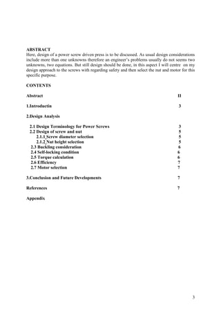
  • 1. ABSTRACT Here, design of a power screw driven press is to be discussed. As usual design considerations include more than one unknowns therefore an engineer’s problems usually do not seems two unknowns, two equations. But still design should be done, in this aspect I will centre on my design approach to the screws with regarding safety and then select the nut and motor for this specific purpose. 3 CONTENTS Abstract II 1.Introductin 3 2.Design Analysis 2.1 Design Terminology for Power Screws 3 2.2 Design of screw and nut 5 2.1.1 Screw diameter selection 5 2.1.2 Nut height selection 5 2.3 Buckling consideration 6 2.4 Self-locking condition 6 2.5 Torque calculation 6 2.6 Efficiency 7 2.7 Motor selection 7 3.Conclusion and Future Developments 7 References 7 Appendix
  • 2. 1. INTRODUCTION I will initialize my design by selecting a screw that is available for me (say in the foundation) and then check it for safety if satisfied or not. And later on consideration of self locking condition, efficiency and required power input according to the selected screw is going to be done for the understanding of practicalability to life. Finally a nut for the screw is selected by regarding bearing and shear stresses. 4 2. DESIGN ANALYSIS Fig 1. A schematic example of application of power screws to a power driven press is shown in figure 1. The some of the desired properties are tabulated as below. By using this table the screw, nut and motor for our pressing operation is going to be selected from standard tables or in other words from machineries catalogue. As seen from the figure 1. , pressing operation is the reverse organization of raising a load so our job is again as in the raising. This is important in order not to confuse lowering or rising.
  • 3. 5 Screw pitch, p(mm) 6 Screw threads Triple Factor of safety, n 3 Load per screw , F(tons) 4 Friction coefficient, μ 0,22 Motor speed, n(rpm) 800 Material of screw 080M50CD Screw Ultimate Strength, Sut (MPa) 650 Screw Yield Strength, Sy(MPa) 510 Screw Modulus of elasticity, E (GPa) 207 Material of nut ASTM Gray Cast Iron Nut Ultimate Strength, Suc (MPa) 670 Nut Yield Strength, Sy(MPa) 220 Table 1. 2.1 Design Terminology for Power Screws A power screw of outside diameter, do, is designed to have a thread pitch, p. The application of the device requires the screw to lift or lower the load. (in our case press the load which is in the same manner as lifting the load). The coefficient of friction for the thread is μt and for the collar μc (in our case collar is not used so no collar friction exists). Fig2. Unwrapping one thread the following wedge geometry results: Where >= Lead angle, L=Lead, Dm=mean diameter of the contact, For a single threaded screw L is the same as the pitch but for double or triple threaded screws L is equal to pitch times number of thread for one rotation of screw. (in our case a triple threaded screw is used)
  • 4. 6 Fig 3. 2.2 Design of screw and nut, 2.2.1 Screw diameter selection, From table 1. a screw which is triple threaded and having a 6 mm pitch exists. Since the diameter of the screw is needed for our calculations, selecting a metric screw having, p=6 and going on my calculation will not be wrong unless the screw I selected does not ensure the safety concern. Our possible choice of diameters for a metric grade 6mm pitch are, 64, 72, 80, 90, 100 for coarse-pitch series. Let’s start our design with M 64.6 . Calculations according to M64.6 screw; mean diameter, dm=d – p/2 = 64 – 6/2 =61 mm, pitch, p=6 mm, Lead, L=3*6=18 mm, F=mg=4000*9.81=40 kN(approximately), F(load factor of sfety included)=F*n=40*4= 160 kN, Now check the strength of the screw in order to be sure that we are on the safe side wrt n=4; 650 = = = MPa 10.88 Fn 160000 c 59.7 At 2680 u = = = 59,7 c n which is safer than desired. Note: If we don’t have to use a 6mm pitch screw with respect to standards a smaller diameter screw will be enough for strenght consideration. So we can continue our design with M64.6 screw . 2.2.2 Nut height selection, Check shearing of threads for h, Fn dh s 2 = s = Ssy = 0.5Sy = 0.5*510 = 255MPa h=6.88 mm Check shearing of nut for h, Fn drh s 2 = h=7.98 mm, Check bearing stress of nut for h,
  • 5. compareb with Suc, since we have already included factor of safety n 7 4 pFn h d 2 dr 2 ( ) b − = by rising force. 4 pFn 2 2 Suc d dr ( ) h − = h=2.49 mm After these calculations we can decide h for our nut as 8 mm wrt shearing of nut . 2.3 Buckling consideration Now we should consider buckling for designing the length of the screw. Since we don’t know the column is either Euler’s or Johnson’s, we need to make an assumption. Since the loading is axial my suggestion is Euler’s column. 4 * Inertia, 4 555497.2 64 mm dr I = = C is equal to 0.25 since our situation best fits one end fixed and one end free. 2 C EI Critical laod, 2 L Pcr = If we equalize Pcr to F*n, then we will get the maximum available length of the screw . When n=4 and E=207GPa from table 1.; L=1331 mm Select L= 1m for our case will give Pcr=283.7kN ; Compare the applied load and the critical load in order to prevent buckling, Pcr=283.7kN F= 40kN . But now there is one more step which is cheking our assumption; 44.75 2 2 CE L = = 1 Sy k 62.5 4 = L = D L k L L Check if k k 1 44.75 62.5, Therefore our assumption is correct. Designing our screw length as 1 meter will be safe for buckling. 2.4 Self-locking condition, The condition for self locking is μ tan or L μ let’s compare, dm 0.22 0.09 therfore self-locking condition is established for our situation. 2.5 Torque calculation After completing screw design, we can calculate the required torque(raising load) for pressing operation. μ * * * * F dm L dm − + = dm L Tr μ 2 when we put the values into eqaution from table 1 and use M64.6 screw; Tr =1564,3 Nm =1,565 kNm
  • 6. 8 2.6 Efficiency 0.292 FL To = = = 2 Tr T e =29.2% Our design has an efficiency of 29.2 percent 2.7 Motor selection Since there exists a gear ratio of 4 between motor and screw head gear, the velocity ratio will also be 4. From table 1. the motor’s angular velocity is suggested as 800 rpm so we can calculate screw velocity w as; Wscrew=800/4=200 rpm 200rpm=200*2A/60 =20.94 rad/sec. Power=T*w=1.565 * 21 = 32.865 kw 32.865kw=32.865/0.745=44 hp So a 45 hp G.E (50 hertz) Electric motor, 400/440 volt, 725 rpm or 50 hp G.G.E Electric motor, 460 volt, 1170 rpm may be suggested for our design. We have concluded our power screw driven press design by using a M64.6 grade screw in length of 1 meter , a 8mm in height nut and a 45 hp electic motor. 3.CONCLUSIONS AND FUTURE IMPROVEMENTS We have started our design by assumptions and then realized them step by step and ensured safety by using standardized screws, nuts and selecting a widely used electric motor. As seen our way of solution design is not a straight forward problem but needs engineering judgement. After mechanical design analysis a further step should be cost analysis in order to say; our design is just ready for manufacturing. REFERENCES 1. J.Hüseyin Filiz. Problems on the design of machine elements. 2. Joseph E.Shigley, Charles R.Mischke, Richard G.Budynas (7th edition). Mechanical Engineering design. 3. www.FlyPress.com 4. www.Savonaequip.com