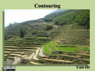
SlideShare una empresa de Scribd logo
1 de 51
Contouring
Unit-III
Contouring
Contouring
• Contour – définitions, objectives, contour
interval, horizontal equivalent, uses and
characteristics of contour lines, methods of
plotting contours, direct and indirect methods
of contouring, Contour gradient.
Levelling and Contouring
Contour Line
• A contour line may be defined as “An imaginary
line passing through points of equal reduced
levels”. A contour line may also be defined “as
the intersection of a level surface with the
surface of the earth”. Thus, contour lines on a
plan illustrates the topography of the area.
• For ex a contour of 90 m indicates that all the
points on this line have RL of 90 m. Similarly, in
a contour of 89 m all the points have RL of 89 m
and so on.
Contour Line
Contour Interval
• The vertical distance between two consecutive
contours is known as a contour interval.
• For ex, a map indicates contour lines of 90 m, 89
m, 88 m and so on, the contour interval is 1m.
• This interval depends upon the following
factors:
• The nature of the ground (i.e. . Whether flat or
steep)
• The scale of the map, and The purpose of the
survey.
Contour Interval
Contour Interval
• Contour intervals for flat ground are generally small,
e.g.. 0.25 m, 0.5 m, 0.75 m
• The contour interval for a steep slope in a hilly area is
generally greater, e.g.. 5 m, 10 m, 15 m, etc.
• Again, for a small scale map, the interval may be of 1
m, 2 m, 3 m, etc.
• Contour interval is kept large up to 2 m for projects
such as highways and railways, whereas it is kept as
small as 0.5 m for measurement of earthwork, building
sites, dams, etc.
• It is desirable to have a constant contour interval for a
particular map.
Horizontal Equivalent
• The horizontal distance between any two
consecutive contours is known as horizontal
equivalent. It is not constant. It varies from
point to point depending upon the steepness of
the ground. Steeper the ground, lesser is the
horizontal equivalent.
Use of Contour Map
• Contour maps provide valuable information about the topography of
the area, whether it is flat, undulating or mountainoueous. The
nature of the ground surface of an area can be understood by
studying a contour map.
The following are the specific uses of the contour map.
• To select sites for engineering projects such as roads, canals,
railways.
• To find the possible route of communication between different
places.
• The capacity of a reservoir and the area of submergence can be
computed
• To ascertain the indivisibility of stations.
• To ascertain the profile of the ground surface along any direction.
• A suitable route for given gradient can be marked on the map.
Use of Contour Map
• To estimate the quantity of
cutting, filling, etc.
• To know the drainage characteristics of the
area. It helps to select sites for
culverts, bridges, drainage system.
Use of Contour Map
Characteristics of Contours
• Since every point on a contour line has the
same elevation, a contour map with a constant
interval portrays the conformation of the
ground in a characteristics manner. The
knowledge of contour characteristics helps in
identifying the natural features of the area
from the given map and in avoiding mistakes
in plotting the contours correctly.
Characteristics of Contours
• The following characteristics help in plotting or
reading a constant map.
• All the points on a contour line have the same
elevation. The elevations of the contour are indicated
either by inserting the figure in a break in respective
contour or printed close to the contour.
• Two contour lines do not intersect with each other.
• Contour lines always from a closed circuit. But these
lines may be within or outside the limit of the map.
• Contour do not have sharp turning.
Characteristics of Contours
• The contour lines are closer near the top of a
hill or high ground and wide apart near the foot.
This indicates a very steep slope towards the
peak and a flatter slope towards the foot.
• The contour lines are closer near the bank of a
pond or depression and wide towards the
centre. This indicates a steep slope near the
bank and a flatter slope at the centre.
• Uniformly spaced contour lines indicate a
uniform slope.
Characteristics of Contours
• A series of closed contour always indicates a depression
or summit. The lower values being inside the loop
indicates a depression and the higher values being inside
the loop indicates a summit. (Hillock)
• Contour deflect uphill at valley lines and downhill at the
ridge lines. Contour lines in U-shape cross a ridge and V-
shape cross a valley at ridge angles. The concavity in
contour lines is towards higher ground in the case of ridge
and towards lower ground in the case of valley.
• Contour lines meeting at a point indicate a vertical cliff.
• Contour lines cannot cross one another, except in the
case of an overhanging cliff. But the overhanging portion
must be shown by a dotted line.
Typical Land features and their
contour forms
Typical Land features and their
contour forms
Typical Land features and their
contour forms
Methods of Contouring
• Contouring requires the planimetric position of
the points whose elevation have been
determined by leveling. The methods of
locating contours, therefore depending upon
the instruments used to determine the
horizontal as well as vertical position of
several points in the area.
Methods of Contouring
• Broadly, the method can be divided into the
following two classes.
• Direct methods
• Indirect methods
Methods of Contouring
Direct Method
• In the direct method of contouring, the reduced level of
various selected points on a contour line are obtained and
their positions are located. The contours are then drawn
by joining these points. It is a very accurate method but it
is slow and tedious.
• This method is employed only for small area where
superior accuracy is demanded. The method of locating
contours directly consists of horizontal and vertical
control. The horizontal control for a small area can be
exercised by a chain or tape and a large area by compass,
theodolite or plane table. For vertical control either a level
and staff or a hand level may be used.
Methods of Contouring
By Level and Staff
• The method consists of locating a series of points on
the ground having the same elevation by using a level
and leveling staff. Instrument is setup in such a way
that number of readings can be taken from the area to
be surveyed. The instrument is set up and RL of HI is
determined from the nearest benchmark. For a
particular contour value, the staff reading is worked
out. A series of points having the same staff reading is
worked out, and thus the same elevations are plotted
and joined by a smooth curve.
Methods of Contouring
By Hand Level
• The principle used is the same as that used in
the method using a level and staff. Instead of
the hand level, an abbey level may also be
used. However this method is very rapid and is
preferred for certain works.
Methods of Contouring
Indirect Methods
• Indirect methods are less expensive, less time
consuming and less tedious as compared with
the direct methods. These methods are
commonly employed in small scale survey of
large areas.
Methods of Contouring
• There are three different ways of employing
the indirect methods of contouring
• (i) Grid Method
• (ii) Cross-Sectional Method
• (iii) Radial line method or
Tachometric method
Methods of Contouring
Grid Method
• If the area is not large, it is divided into a grid or series of
squares. The grid size may vary from 5m x 5 m to 25 m x
25 m depending upon the nature of the ground, the contour
interval and the scale of the map. The grid corner are
marked on the ground and spot levels of these corners are
then determined by normal method of leveling using a level.
• The grid is plotted to the scale of the map and the spot
levels of the grid corners are entered, the contours of
desired values are then locked by interpolation. This method
is very suitable for a small open area where contour are
required at a closed vertical interval
Methods of Contouring
Cross-Sectioning Method
• In this method, suitable spaced cross –sections are
projected on either side of the centre line of the
area. Several points are chosen at reasonable
distances on either sides. The observations are
made in the usual manner with a level. The cross-
section lines are plotted to the scale, the points on
these lines are marked and reduced levels are
entered. The contours of desired values are then
located by interpolation. This method is suitable
for road, railway and canal survey.
Methods of Contouring
Radial Line Method or Tachometric Method
• In this method, a number of radial lines are set out at
known angular interval (i.e. 15 0 or 30 0) at each station.
The point are selected on a line depend on the nature of
the ground surface. Instead of the level, a tachometer
may be used. The observations are taken on the staff
stations and elevations and distances are then
calculated. A traverse and radial lines are plotted to the
scale RLs of the point entered. The contour of desired
values are then located by interpolation . This method is
convenient in hilly area.
Methods of Contouring
• Comparison of direct and Indirect methods of
contouring
Direct Method Indirect Method
Most accurate but slow and tedious Not so accurate but rapid and less tedious
Expensive Cheaper
Not suitable for hilly area Suitable for hilly area
During the work calculations can be done Calculations are not required in the field
Calculation can not be checked after
contouring
Calculation can be checked as and when
required
Radial Line Method
Interpolation of Contours
• The process of locating the contours
proportionately between the plotted point is
termed interpolation may be done by:
• Estimation
• Arithmetical Calculation
• Graphical Method
Interpolation of Contours
Estimation
• The points on the required contour are located
by eye judgment or estimation between points
whose elevations are already known. This
method is good for small scale maps. It is
assumed that slope between the ground points
is uniform.
Interpolation of Contours
Arithmetic Calculations
• This methods is used when high accuracy is
required and scale of the map is of
intermediate or large. In this method the
distances between two points of known
elevation are accurately measured. Then with
the help of arithmetic calculations, the
positions of the required elevation points are
computed.
Interpolation of Contours
Graphical Method
• When high accuracy is required and many
interpolation are to be made, this method of
plotting contours proves to be most rapid and
convenient. For this purpose tracing paper is
used.
Plotting of a Contour Map
• Before plotting the contour map, suitable scale is
selected.
• e.g. 1 cm = 1 m, 1 cm = 2 m, 1 cm = 2.5 m, 1 cm
= 4 m or 1 cm = 5 m etc. Here 1 cm = 2m is
selected.
• A horizontal line is drawn as the centre line
• The chainages are marked along the horizontal
line according to the scale.
• Ground levels are written from the level book
according to the chainage.
Plotting of a Contour Map
• The cross-section (L/s and R/S) are also plotted
(perpendicular lines) at each of the chainage.
• By interpolation contours are joined by smooth
curves keeping in mind the characteristics of
contour.
• First find out maximum and minimum RL values
and then first plot full values contour lines i.e.. 47
, 48, 49 etc. Contour interval is 1 m. After plotting
these contour lines reduces contour interval and it
is taken 0.5 m and contour lines i.e. 47.5, 48.5,
49.5 etc are plotted.
• Contour lines are then inked.
Plotting of a Contour Map
References
• “Surveying and Levelling” Vol- I
Kanetkar and Kulkarni (2011)
• “ Surveying” Vol- I
Dr. B.C. Punamia
Thanks !

Más contenido relacionado

La actualidad más candente

INTRODUCTION TO SURVEYING
INTRODUCTION TO SURVEYINGINTRODUCTION TO SURVEYING
INTRODUCTION TO SURVEYINGfarhana saiyed
 
Theodolite traversing, purpose and principles of theodolite traversing
Theodolite traversing, purpose and principles of theodolite traversingTheodolite traversing, purpose and principles of theodolite traversing
Theodolite traversing, purpose and principles of theodolite traversingDolat Ram
 
Chain surveying.1
Chain surveying.1Chain surveying.1
Chain surveying.1Decentumang
 
Surveying and levelling
Surveying and levellingSurveying and levelling
Surveying and levellingParimal Jha
 
Total station Surveying
Total station SurveyingTotal station Surveying
Total station SurveyingKiran M
 
tacheometric surveying
tacheometric surveyingtacheometric surveying
tacheometric surveyingMujeeb Muji
 
Classification of surveying
Classification of surveyingClassification of surveying
Classification of surveyingAshishBhadani4
 
Earthwork Volume Calculation Methods
Earthwork Volume Calculation MethodsEarthwork Volume Calculation Methods
Earthwork Volume Calculation Methodsriyasood003
 
Traverse Survey Part 1/2
Traverse Survey Part 1/2Traverse Survey Part 1/2
Traverse Survey Part 1/2Muhammad Zubair
 
1.1 Linear measurement original: Chaining & Ranging
1.1 Linear measurement original: Chaining & Ranging1.1 Linear measurement original: Chaining & Ranging
1.1 Linear measurement original: Chaining & RangingRakesh Verma
 
Tacheometric surveying ppt
Tacheometric surveying pptTacheometric surveying ppt
Tacheometric surveying pptNaufil Sayyad
 
Computation of area
Computation of areaComputation of area
Computation of areaKavin Raval
 

La actualidad más candente (20)

Total Station surveying
Total Station surveyingTotal Station surveying
Total Station surveying
 
INTRODUCTION TO SURVEYING
INTRODUCTION TO SURVEYINGINTRODUCTION TO SURVEYING
INTRODUCTION TO SURVEYING
 
Theodolite traversing, purpose and principles of theodolite traversing
Theodolite traversing, purpose and principles of theodolite traversingTheodolite traversing, purpose and principles of theodolite traversing
Theodolite traversing, purpose and principles of theodolite traversing
 
surveying contouring
surveying contouring surveying contouring
surveying contouring
 
Chain surveying.1
Chain surveying.1Chain surveying.1
Chain surveying.1
 
Compass Surveying
Compass Surveying Compass Surveying
Compass Surveying
 
Surveying and levelling
Surveying and levellingSurveying and levelling
Surveying and levelling
 
Total station Surveying
Total station SurveyingTotal station Surveying
Total station Surveying
 
Theodolite Surveying
Theodolite Surveying Theodolite Surveying
Theodolite Surveying
 
Curves
CurvesCurves
Curves
 
Plane Table Surveying PPt
Plane Table Surveying PPtPlane Table Surveying PPt
Plane Table Surveying PPt
 
tacheometric surveying
tacheometric surveyingtacheometric surveying
tacheometric surveying
 
Classification of surveying
Classification of surveyingClassification of surveying
Classification of surveying
 
Curve setting ppt
Curve setting pptCurve setting ppt
Curve setting ppt
 
Earthwork Volume Calculation Methods
Earthwork Volume Calculation MethodsEarthwork Volume Calculation Methods
Earthwork Volume Calculation Methods
 
Traverse Survey Part 1/2
Traverse Survey Part 1/2Traverse Survey Part 1/2
Traverse Survey Part 1/2
 
1.1 Linear measurement original: Chaining & Ranging
1.1 Linear measurement original: Chaining & Ranging1.1 Linear measurement original: Chaining & Ranging
1.1 Linear measurement original: Chaining & Ranging
 
Tacheometric surveying ppt
Tacheometric surveying pptTacheometric surveying ppt
Tacheometric surveying ppt
 
Theodolite Traversing
Theodolite TraversingTheodolite Traversing
Theodolite Traversing
 
Computation of area
Computation of areaComputation of area
Computation of area
 

Destacado

Destacado (9)

The usage of the theodolite
The usage of the theodolite The usage of the theodolite
The usage of the theodolite
 
4 dumpy level surveying introduction
4 dumpy level surveying introduction4 dumpy level surveying introduction
4 dumpy level surveying introduction
 
Types of level
Types of levelTypes of level
Types of level
 
Field Astronomy
Field AstronomyField Astronomy
Field Astronomy
 
Glass powder replacement for cement.by ananth k p coorg
Glass powder replacement for cement.by ananth k p coorgGlass powder replacement for cement.by ananth k p coorg
Glass powder replacement for cement.by ananth k p coorg
 
Area & Volume
Area & VolumeArea & Volume
Area & Volume
 
6 dumpy levels. example of use
6 dumpy levels. example of use6 dumpy levels. example of use
6 dumpy levels. example of use
 
Volume
VolumeVolume
Volume
 
Industries
IndustriesIndustries
Industries
 

Similar a Contouring

contouring Surveying of Civil Engineering.pptx
contouring Surveying of Civil Engineering.pptxcontouring Surveying of Civil Engineering.pptx
contouring Surveying of Civil Engineering.pptxramjan14
 
contouring-180417110533.pdf
contouring-180417110533.pdfcontouring-180417110533.pdf
contouring-180417110533.pdfshucaybcabdi
 
Contour maps: preparation and understanding.
Contour maps: preparation and understanding.Contour maps: preparation and understanding.
Contour maps: preparation and understanding.VIVEK CHAUHAN
 
Contouring in "Survey & Levelling".
Contouring in "Survey & Levelling".Contouring in "Survey & Levelling".
Contouring in "Survey & Levelling".Ar. Avitesh
 
Contour lines - Survey & Levelling
Contour lines - Survey & LevellingContour lines - Survey & Levelling
Contour lines - Survey & LevellingAr. Avitesh
 
Information About Contour And its charecteristics
Information About Contour And its charecteristicsInformation About Contour And its charecteristics
Information About Contour And its charecteristicsAshraf Sayyed
 
surveyf tururu ururtu65 6ru5uu56 686585 868
surveyf tururu ururtu65 6ru5uu56 686585 868surveyf tururu ururtu65 6ru5uu56 686585 868
surveyf tururu ururtu65 6ru5uu56 686585 868RahulSinghParihar18
 
1 fundamentals
1  fundamentals1  fundamentals
1 fundamentalsWaqas Khan
 
surveying-as.pptx
surveying-as.pptxsurveying-as.pptx
surveying-as.pptxAnshulSud1
 
Study of contours.pptx
Study of contours.pptxStudy of contours.pptx
Study of contours.pptxkarthika138842
 
CET205 Module 1 Contouring.pdf
CET205 Module 1 Contouring.pdfCET205 Module 1 Contouring.pdf
CET205 Module 1 Contouring.pdfKumkumaIp
 
Week1 introductiontobasicsurveying
Week1 introductiontobasicsurveyingWeek1 introductiontobasicsurveying
Week1 introductiontobasicsurveyingJackie Arul
 
Chain surveying and offset
Chain surveying and offsetChain surveying and offset
Chain surveying and offsetMir Zafarullah
 

Similar a Contouring (20)

contouring Surveying of Civil Engineering.pptx
contouring Surveying of Civil Engineering.pptxcontouring Surveying of Civil Engineering.pptx
contouring Surveying of Civil Engineering.pptx
 
contouring-180417110533.pdf
contouring-180417110533.pdfcontouring-180417110533.pdf
contouring-180417110533.pdf
 
Contouring
ContouringContouring
Contouring
 
Contouring
ContouringContouring
Contouring
 
Contour maps: preparation and understanding.
Contour maps: preparation and understanding.Contour maps: preparation and understanding.
Contour maps: preparation and understanding.
 
CONTOURING
CONTOURINGCONTOURING
CONTOURING
 
Contouring in "Survey & Levelling".
Contouring in "Survey & Levelling".Contouring in "Survey & Levelling".
Contouring in "Survey & Levelling".
 
Contour lines - Survey & Levelling
Contour lines - Survey & LevellingContour lines - Survey & Levelling
Contour lines - Survey & Levelling
 
Information About Contour And its charecteristics
Information About Contour And its charecteristicsInformation About Contour And its charecteristics
Information About Contour And its charecteristics
 
surveyf tururu ururtu65 6ru5uu56 686585 868
surveyf tururu ururtu65 6ru5uu56 686585 868surveyf tururu ururtu65 6ru5uu56 686585 868
surveyf tururu ururtu65 6ru5uu56 686585 868
 
1. Intro to Surveying.pdf
1. Intro to Surveying.pdf1. Intro to Surveying.pdf
1. Intro to Surveying.pdf
 
Unit 2
Unit 2Unit 2
Unit 2
 
Contouring
ContouringContouring
Contouring
 
Contouring
ContouringContouring
Contouring
 
1 fundamentals
1  fundamentals1  fundamentals
1 fundamentals
 
surveying-as.pptx
surveying-as.pptxsurveying-as.pptx
surveying-as.pptx
 
Study of contours.pptx
Study of contours.pptxStudy of contours.pptx
Study of contours.pptx
 
CET205 Module 1 Contouring.pdf
CET205 Module 1 Contouring.pdfCET205 Module 1 Contouring.pdf
CET205 Module 1 Contouring.pdf
 
Week1 introductiontobasicsurveying
Week1 introductiontobasicsurveyingWeek1 introductiontobasicsurveying
Week1 introductiontobasicsurveying
 
Chain surveying and offset
Chain surveying and offsetChain surveying and offset
Chain surveying and offset
 

Más de GAURAV. H .TANDON

Suicide Prevention through Architecture (Building) and City Planning
Suicide Prevention through  Architecture (Building) and City PlanningSuicide Prevention through  Architecture (Building) and City Planning
Suicide Prevention through Architecture (Building) and City PlanningGAURAV. H .TANDON
 
Suicide Prevention through Architecture (Building) and City Planning
Suicide Prevention through  Architecture (Building) and City PlanningSuicide Prevention through  Architecture (Building) and City Planning
Suicide Prevention through Architecture (Building) and City PlanningGAURAV. H .TANDON
 
Digital Detoxing in Smart Cities
Digital Detoxing in Smart CitiesDigital Detoxing in Smart Cities
Digital Detoxing in Smart CitiesGAURAV. H .TANDON
 
Digital Detoxing in Smart Cities
Digital Detoxing in Smart CitiesDigital Detoxing in Smart Cities
Digital Detoxing in Smart CitiesGAURAV. H .TANDON
 
Crash for Cash-Organized Crime (COC).pptx
Crash for Cash-Organized Crime (COC).pptxCrash for Cash-Organized Crime (COC).pptx
Crash for Cash-Organized Crime (COC).pptxGAURAV. H .TANDON
 
Ecological Footprint (1).pptx
Ecological Footprint (1).pptxEcological Footprint (1).pptx
Ecological Footprint (1).pptxGAURAV. H .TANDON
 
The unethical practice of gift giving to doctors by pharma companies
The unethical practice of gift giving to doctors by pharma companiesThe unethical practice of gift giving to doctors by pharma companies
The unethical practice of gift giving to doctors by pharma companiesGAURAV. H .TANDON
 
Gamification of Smart Cities
Gamification of Smart Cities Gamification of Smart Cities
Gamification of Smart Cities GAURAV. H .TANDON
 
Collusion and Fraud Detection on Electronic Energy Meters
Collusion and Fraud Detection on Electronic Energy Meters Collusion and Fraud Detection on Electronic Energy Meters
Collusion and Fraud Detection on Electronic Energy Meters GAURAV. H .TANDON
 
Cyber Security in Smart Buildings
Cyber Security in Smart Buildings Cyber Security in Smart Buildings
Cyber Security in Smart Buildings GAURAV. H .TANDON
 

Más de GAURAV. H .TANDON (20)

Suicide Prevention through Architecture (Building) and City Planning
Suicide Prevention through  Architecture (Building) and City PlanningSuicide Prevention through  Architecture (Building) and City Planning
Suicide Prevention through Architecture (Building) and City Planning
 
Suicide Prevention through Architecture (Building) and City Planning
Suicide Prevention through  Architecture (Building) and City PlanningSuicide Prevention through  Architecture (Building) and City Planning
Suicide Prevention through Architecture (Building) and City Planning
 
Digital Detoxing in Smart Cities
Digital Detoxing in Smart CitiesDigital Detoxing in Smart Cities
Digital Detoxing in Smart Cities
 
Digital Detoxing in Smart Cities
Digital Detoxing in Smart CitiesDigital Detoxing in Smart Cities
Digital Detoxing in Smart Cities
 
Premerital Sceening .pptx
Premerital Sceening .pptxPremerital Sceening .pptx
Premerital Sceening .pptx
 
Polymath(Renaissance man)
Polymath(Renaissance man)Polymath(Renaissance man)
Polymath(Renaissance man)
 
Crash for Cash-Organized Crime (COC).pptx
Crash for Cash-Organized Crime (COC).pptxCrash for Cash-Organized Crime (COC).pptx
Crash for Cash-Organized Crime (COC).pptx
 
Voting Age .pptx
Voting Age .pptxVoting Age .pptx
Voting Age .pptx
 
Ecological Footprint (1).pptx
Ecological Footprint (1).pptxEcological Footprint (1).pptx
Ecological Footprint (1).pptx
 
Urban Heat Island Effect
Urban Heat Island EffectUrban Heat Island Effect
Urban Heat Island Effect
 
Communication Skills
Communication SkillsCommunication Skills
Communication Skills
 
The unethical practice of gift giving to doctors by pharma companies
The unethical practice of gift giving to doctors by pharma companiesThe unethical practice of gift giving to doctors by pharma companies
The unethical practice of gift giving to doctors by pharma companies
 
Compassionate Cities
Compassionate CitiesCompassionate Cities
Compassionate Cities
 
Gamification of Smart Cities
Gamification of Smart Cities Gamification of Smart Cities
Gamification of Smart Cities
 
Anti-Microbial Copper
Anti-Microbial Copper Anti-Microbial Copper
Anti-Microbial Copper
 
Smart Forest City
Smart Forest City Smart Forest City
Smart Forest City
 
Smart forest cities
Smart forest cities Smart forest cities
Smart forest cities
 
Automotive Hacking
Automotive Hacking Automotive Hacking
Automotive Hacking
 
Collusion and Fraud Detection on Electronic Energy Meters
Collusion and Fraud Detection on Electronic Energy Meters Collusion and Fraud Detection on Electronic Energy Meters
Collusion and Fraud Detection on Electronic Energy Meters
 
Cyber Security in Smart Buildings
Cyber Security in Smart Buildings Cyber Security in Smart Buildings
Cyber Security in Smart Buildings
 

Último

Crayon Activity Handout For the Crayon A
Crayon Activity Handout For the Crayon ACrayon Activity Handout For the Crayon A
Crayon Activity Handout For the Crayon AUnboundStockton
 
MENTAL STATUS EXAMINATION format.docx
MENTAL     STATUS EXAMINATION format.docxMENTAL     STATUS EXAMINATION format.docx
MENTAL STATUS EXAMINATION format.docxPoojaSen20
 
Contemporary philippine arts from the regions_PPT_Module_12 [Autosaved] (1).pptx
Contemporary philippine arts from the regions_PPT_Module_12 [Autosaved] (1).pptxContemporary philippine arts from the regions_PPT_Module_12 [Autosaved] (1).pptx
Contemporary philippine arts from the regions_PPT_Module_12 [Autosaved] (1).pptxRoyAbrique
 
microwave assisted reaction. General introduction
microwave assisted reaction. General introductionmicrowave assisted reaction. General introduction
microwave assisted reaction. General introductionMaksud Ahmed
 
CARE OF CHILD IN INCUBATOR..........pptx
CARE OF CHILD IN INCUBATOR..........pptxCARE OF CHILD IN INCUBATOR..........pptx
CARE OF CHILD IN INCUBATOR..........pptxGaneshChakor2
 
“Oh GOSH! Reflecting on Hackteria's Collaborative Practices in a Global Do-It...
“Oh GOSH! Reflecting on Hackteria's Collaborative Practices in a Global Do-It...“Oh GOSH! Reflecting on Hackteria's Collaborative Practices in a Global Do-It...
“Oh GOSH! Reflecting on Hackteria's Collaborative Practices in a Global Do-It...Marc Dusseiller Dusjagr
 
Industrial Policy - 1948, 1956, 1973, 1977, 1980, 1991
Industrial Policy - 1948, 1956, 1973, 1977, 1980, 1991Industrial Policy - 1948, 1956, 1973, 1977, 1980, 1991
Industrial Policy - 1948, 1956, 1973, 1977, 1980, 1991RKavithamani
 
Science 7 - LAND and SEA BREEZE and its Characteristics
Science 7 - LAND and SEA BREEZE and its CharacteristicsScience 7 - LAND and SEA BREEZE and its Characteristics
Science 7 - LAND and SEA BREEZE and its CharacteristicsKarinaGenton
 
Micromeritics - Fundamental and Derived Properties of Powders
Micromeritics - Fundamental and Derived Properties of PowdersMicromeritics - Fundamental and Derived Properties of Powders
Micromeritics - Fundamental and Derived Properties of PowdersChitralekhaTherkar
 
Software Engineering Methodologies (overview)
Software Engineering Methodologies (overview)Software Engineering Methodologies (overview)
Software Engineering Methodologies (overview)eniolaolutunde
 
Alper Gobel In Media Res Media Component
Alper Gobel In Media Res Media ComponentAlper Gobel In Media Res Media Component
Alper Gobel In Media Res Media ComponentInMediaRes1
 
APM Welcome, APM North West Network Conference, Synergies Across Sectors
APM Welcome, APM North West Network Conference, Synergies Across SectorsAPM Welcome, APM North West Network Conference, Synergies Across Sectors
APM Welcome, APM North West Network Conference, Synergies Across SectorsAssociation for Project Management
 
Employee wellbeing at the workplace.pptx
Employee wellbeing at the workplace.pptxEmployee wellbeing at the workplace.pptx
Employee wellbeing at the workplace.pptxNirmalaLoungPoorunde1
 
Accessible design: Minimum effort, maximum impact
Accessible design: Minimum effort, maximum impactAccessible design: Minimum effort, maximum impact
Accessible design: Minimum effort, maximum impactdawncurless
 
mini mental status format.docx
mini    mental       status     format.docxmini    mental       status     format.docx
mini mental status format.docxPoojaSen20
 
Introduction to AI in Higher Education_draft.pptx
Introduction to AI in Higher Education_draft.pptxIntroduction to AI in Higher Education_draft.pptx
Introduction to AI in Higher Education_draft.pptxpboyjonauth
 
_Math 4-Q4 Week 5.pptx Steps in Collecting Data
_Math 4-Q4 Week 5.pptx Steps in Collecting Data_Math 4-Q4 Week 5.pptx Steps in Collecting Data
_Math 4-Q4 Week 5.pptx Steps in Collecting DataJhengPantaleon
 

Último (20)

Crayon Activity Handout For the Crayon A
Crayon Activity Handout For the Crayon ACrayon Activity Handout For the Crayon A
Crayon Activity Handout For the Crayon A
 
Model Call Girl in Tilak Nagar Delhi reach out to us at 🔝9953056974🔝
Model Call Girl in Tilak Nagar Delhi reach out to us at 🔝9953056974🔝Model Call Girl in Tilak Nagar Delhi reach out to us at 🔝9953056974🔝
Model Call Girl in Tilak Nagar Delhi reach out to us at 🔝9953056974🔝
 
MENTAL STATUS EXAMINATION format.docx
MENTAL     STATUS EXAMINATION format.docxMENTAL     STATUS EXAMINATION format.docx
MENTAL STATUS EXAMINATION format.docx
 
Contemporary philippine arts from the regions_PPT_Module_12 [Autosaved] (1).pptx
Contemporary philippine arts from the regions_PPT_Module_12 [Autosaved] (1).pptxContemporary philippine arts from the regions_PPT_Module_12 [Autosaved] (1).pptx
Contemporary philippine arts from the regions_PPT_Module_12 [Autosaved] (1).pptx
 
microwave assisted reaction. General introduction
microwave assisted reaction. General introductionmicrowave assisted reaction. General introduction
microwave assisted reaction. General introduction
 
CARE OF CHILD IN INCUBATOR..........pptx
CARE OF CHILD IN INCUBATOR..........pptxCARE OF CHILD IN INCUBATOR..........pptx
CARE OF CHILD IN INCUBATOR..........pptx
 
“Oh GOSH! Reflecting on Hackteria's Collaborative Practices in a Global Do-It...
“Oh GOSH! Reflecting on Hackteria's Collaborative Practices in a Global Do-It...“Oh GOSH! Reflecting on Hackteria's Collaborative Practices in a Global Do-It...
“Oh GOSH! Reflecting on Hackteria's Collaborative Practices in a Global Do-It...
 
Industrial Policy - 1948, 1956, 1973, 1977, 1980, 1991
Industrial Policy - 1948, 1956, 1973, 1977, 1980, 1991Industrial Policy - 1948, 1956, 1973, 1977, 1980, 1991
Industrial Policy - 1948, 1956, 1973, 1977, 1980, 1991
 
Science 7 - LAND and SEA BREEZE and its Characteristics
Science 7 - LAND and SEA BREEZE and its CharacteristicsScience 7 - LAND and SEA BREEZE and its Characteristics
Science 7 - LAND and SEA BREEZE and its Characteristics
 
Micromeritics - Fundamental and Derived Properties of Powders
Micromeritics - Fundamental and Derived Properties of PowdersMicromeritics - Fundamental and Derived Properties of Powders
Micromeritics - Fundamental and Derived Properties of Powders
 
Software Engineering Methodologies (overview)
Software Engineering Methodologies (overview)Software Engineering Methodologies (overview)
Software Engineering Methodologies (overview)
 
Alper Gobel In Media Res Media Component
Alper Gobel In Media Res Media ComponentAlper Gobel In Media Res Media Component
Alper Gobel In Media Res Media Component
 
APM Welcome, APM North West Network Conference, Synergies Across Sectors
APM Welcome, APM North West Network Conference, Synergies Across SectorsAPM Welcome, APM North West Network Conference, Synergies Across Sectors
APM Welcome, APM North West Network Conference, Synergies Across Sectors
 
Employee wellbeing at the workplace.pptx
Employee wellbeing at the workplace.pptxEmployee wellbeing at the workplace.pptx
Employee wellbeing at the workplace.pptx
 
Staff of Color (SOC) Retention Efforts DDSD
Staff of Color (SOC) Retention Efforts DDSDStaff of Color (SOC) Retention Efforts DDSD
Staff of Color (SOC) Retention Efforts DDSD
 
Accessible design: Minimum effort, maximum impact
Accessible design: Minimum effort, maximum impactAccessible design: Minimum effort, maximum impact
Accessible design: Minimum effort, maximum impact
 
mini mental status format.docx
mini    mental       status     format.docxmini    mental       status     format.docx
mini mental status format.docx
 
Introduction to AI in Higher Education_draft.pptx
Introduction to AI in Higher Education_draft.pptxIntroduction to AI in Higher Education_draft.pptx
Introduction to AI in Higher Education_draft.pptx
 
_Math 4-Q4 Week 5.pptx Steps in Collecting Data
_Math 4-Q4 Week 5.pptx Steps in Collecting Data_Math 4-Q4 Week 5.pptx Steps in Collecting Data
_Math 4-Q4 Week 5.pptx Steps in Collecting Data
 
TataKelola dan KamSiber Kecerdasan Buatan v022.pdf
TataKelola dan KamSiber Kecerdasan Buatan v022.pdfTataKelola dan KamSiber Kecerdasan Buatan v022.pdf
TataKelola dan KamSiber Kecerdasan Buatan v022.pdf
 

Contouring

  • 2. Contouring Contouring • Contour – définitions, objectives, contour interval, horizontal equivalent, uses and characteristics of contour lines, methods of plotting contours, direct and indirect methods of contouring, Contour gradient.
  • 4. Contour Line • A contour line may be defined as “An imaginary line passing through points of equal reduced levels”. A contour line may also be defined “as the intersection of a level surface with the surface of the earth”. Thus, contour lines on a plan illustrates the topography of the area. • For ex a contour of 90 m indicates that all the points on this line have RL of 90 m. Similarly, in a contour of 89 m all the points have RL of 89 m and so on.
  • 6. Contour Interval • The vertical distance between two consecutive contours is known as a contour interval. • For ex, a map indicates contour lines of 90 m, 89 m, 88 m and so on, the contour interval is 1m. • This interval depends upon the following factors: • The nature of the ground (i.e. . Whether flat or steep) • The scale of the map, and The purpose of the survey.
  • 8. Contour Interval • Contour intervals for flat ground are generally small, e.g.. 0.25 m, 0.5 m, 0.75 m • The contour interval for a steep slope in a hilly area is generally greater, e.g.. 5 m, 10 m, 15 m, etc. • Again, for a small scale map, the interval may be of 1 m, 2 m, 3 m, etc. • Contour interval is kept large up to 2 m for projects such as highways and railways, whereas it is kept as small as 0.5 m for measurement of earthwork, building sites, dams, etc. • It is desirable to have a constant contour interval for a particular map.
  • 9. Horizontal Equivalent • The horizontal distance between any two consecutive contours is known as horizontal equivalent. It is not constant. It varies from point to point depending upon the steepness of the ground. Steeper the ground, lesser is the horizontal equivalent.
  • 10. Use of Contour Map • Contour maps provide valuable information about the topography of the area, whether it is flat, undulating or mountainoueous. The nature of the ground surface of an area can be understood by studying a contour map. The following are the specific uses of the contour map. • To select sites for engineering projects such as roads, canals, railways. • To find the possible route of communication between different places. • The capacity of a reservoir and the area of submergence can be computed • To ascertain the indivisibility of stations. • To ascertain the profile of the ground surface along any direction. • A suitable route for given gradient can be marked on the map.
  • 11. Use of Contour Map • To estimate the quantity of cutting, filling, etc. • To know the drainage characteristics of the area. It helps to select sites for culverts, bridges, drainage system.
  • 13. Characteristics of Contours • Since every point on a contour line has the same elevation, a contour map with a constant interval portrays the conformation of the ground in a characteristics manner. The knowledge of contour characteristics helps in identifying the natural features of the area from the given map and in avoiding mistakes in plotting the contours correctly.
  • 15. Characteristics of Contours • The following characteristics help in plotting or reading a constant map. • All the points on a contour line have the same elevation. The elevations of the contour are indicated either by inserting the figure in a break in respective contour or printed close to the contour. • Two contour lines do not intersect with each other. • Contour lines always from a closed circuit. But these lines may be within or outside the limit of the map. • Contour do not have sharp turning.
  • 17. Characteristics of Contours • The contour lines are closer near the top of a hill or high ground and wide apart near the foot. This indicates a very steep slope towards the peak and a flatter slope towards the foot. • The contour lines are closer near the bank of a pond or depression and wide towards the centre. This indicates a steep slope near the bank and a flatter slope at the centre. • Uniformly spaced contour lines indicate a uniform slope.
  • 22. Characteristics of Contours • A series of closed contour always indicates a depression or summit. The lower values being inside the loop indicates a depression and the higher values being inside the loop indicates a summit. (Hillock) • Contour deflect uphill at valley lines and downhill at the ridge lines. Contour lines in U-shape cross a ridge and V- shape cross a valley at ridge angles. The concavity in contour lines is towards higher ground in the case of ridge and towards lower ground in the case of valley. • Contour lines meeting at a point indicate a vertical cliff. • Contour lines cannot cross one another, except in the case of an overhanging cliff. But the overhanging portion must be shown by a dotted line.
  • 23. Typical Land features and their contour forms
  • 24. Typical Land features and their contour forms
  • 25. Typical Land features and their contour forms
  • 26. Methods of Contouring • Contouring requires the planimetric position of the points whose elevation have been determined by leveling. The methods of locating contours, therefore depending upon the instruments used to determine the horizontal as well as vertical position of several points in the area.
  • 27. Methods of Contouring • Broadly, the method can be divided into the following two classes. • Direct methods • Indirect methods
  • 28. Methods of Contouring Direct Method • In the direct method of contouring, the reduced level of various selected points on a contour line are obtained and their positions are located. The contours are then drawn by joining these points. It is a very accurate method but it is slow and tedious. • This method is employed only for small area where superior accuracy is demanded. The method of locating contours directly consists of horizontal and vertical control. The horizontal control for a small area can be exercised by a chain or tape and a large area by compass, theodolite or plane table. For vertical control either a level and staff or a hand level may be used.
  • 30. Methods of Contouring By Level and Staff • The method consists of locating a series of points on the ground having the same elevation by using a level and leveling staff. Instrument is setup in such a way that number of readings can be taken from the area to be surveyed. The instrument is set up and RL of HI is determined from the nearest benchmark. For a particular contour value, the staff reading is worked out. A series of points having the same staff reading is worked out, and thus the same elevations are plotted and joined by a smooth curve.
  • 32. Methods of Contouring By Hand Level • The principle used is the same as that used in the method using a level and staff. Instead of the hand level, an abbey level may also be used. However this method is very rapid and is preferred for certain works.
  • 34. Methods of Contouring Indirect Methods • Indirect methods are less expensive, less time consuming and less tedious as compared with the direct methods. These methods are commonly employed in small scale survey of large areas.
  • 35. Methods of Contouring • There are three different ways of employing the indirect methods of contouring • (i) Grid Method • (ii) Cross-Sectional Method • (iii) Radial line method or Tachometric method
  • 36. Methods of Contouring Grid Method • If the area is not large, it is divided into a grid or series of squares. The grid size may vary from 5m x 5 m to 25 m x 25 m depending upon the nature of the ground, the contour interval and the scale of the map. The grid corner are marked on the ground and spot levels of these corners are then determined by normal method of leveling using a level. • The grid is plotted to the scale of the map and the spot levels of the grid corners are entered, the contours of desired values are then locked by interpolation. This method is very suitable for a small open area where contour are required at a closed vertical interval
  • 39. Methods of Contouring Cross-Sectioning Method • In this method, suitable spaced cross –sections are projected on either side of the centre line of the area. Several points are chosen at reasonable distances on either sides. The observations are made in the usual manner with a level. The cross- section lines are plotted to the scale, the points on these lines are marked and reduced levels are entered. The contours of desired values are then located by interpolation. This method is suitable for road, railway and canal survey.
  • 40. Methods of Contouring Radial Line Method or Tachometric Method • In this method, a number of radial lines are set out at known angular interval (i.e. 15 0 or 30 0) at each station. The point are selected on a line depend on the nature of the ground surface. Instead of the level, a tachometer may be used. The observations are taken on the staff stations and elevations and distances are then calculated. A traverse and radial lines are plotted to the scale RLs of the point entered. The contour of desired values are then located by interpolation . This method is convenient in hilly area.
  • 41. Methods of Contouring • Comparison of direct and Indirect methods of contouring Direct Method Indirect Method Most accurate but slow and tedious Not so accurate but rapid and less tedious Expensive Cheaper Not suitable for hilly area Suitable for hilly area During the work calculations can be done Calculations are not required in the field Calculation can not be checked after contouring Calculation can be checked as and when required
  • 43. Interpolation of Contours • The process of locating the contours proportionately between the plotted point is termed interpolation may be done by: • Estimation • Arithmetical Calculation • Graphical Method
  • 44. Interpolation of Contours Estimation • The points on the required contour are located by eye judgment or estimation between points whose elevations are already known. This method is good for small scale maps. It is assumed that slope between the ground points is uniform.
  • 45. Interpolation of Contours Arithmetic Calculations • This methods is used when high accuracy is required and scale of the map is of intermediate or large. In this method the distances between two points of known elevation are accurately measured. Then with the help of arithmetic calculations, the positions of the required elevation points are computed.
  • 46. Interpolation of Contours Graphical Method • When high accuracy is required and many interpolation are to be made, this method of plotting contours proves to be most rapid and convenient. For this purpose tracing paper is used.
  • 47. Plotting of a Contour Map • Before plotting the contour map, suitable scale is selected. • e.g. 1 cm = 1 m, 1 cm = 2 m, 1 cm = 2.5 m, 1 cm = 4 m or 1 cm = 5 m etc. Here 1 cm = 2m is selected. • A horizontal line is drawn as the centre line • The chainages are marked along the horizontal line according to the scale. • Ground levels are written from the level book according to the chainage.
  • 48. Plotting of a Contour Map • The cross-section (L/s and R/S) are also plotted (perpendicular lines) at each of the chainage. • By interpolation contours are joined by smooth curves keeping in mind the characteristics of contour. • First find out maximum and minimum RL values and then first plot full values contour lines i.e.. 47 , 48, 49 etc. Contour interval is 1 m. After plotting these contour lines reduces contour interval and it is taken 0.5 m and contour lines i.e. 47.5, 48.5, 49.5 etc are plotted. • Contour lines are then inked.
  • 49. Plotting of a Contour Map
  • 50. References • “Surveying and Levelling” Vol- I Kanetkar and Kulkarni (2011) • “ Surveying” Vol- I Dr. B.C. Punamia