SlideShare una empresa de Scribd logo
1 de 217
Descargar para leer sin conexión
182   Part I: The Motherboard and Its Components


                                                       TAG-
                SRAM            SRAM                   RAM

        PIN80                   PIN43   PIN42                   PIN1


      Figure 7-3: A Cache on a Stick (COAST) module.


      Working with Cache
      In a vast majority of cases, you wouldn’t be adding cache memory to a PC.
      However, if you find it necessary, the guidelines in the following sections should
      provide you with some help.

      Installing a cache module
      First, review the motherboard’s documentation or check with the PC manufacturer
      or vendor to determine whether the PC is able to expand its L2 cache. If no caching
      is installed and you wish to include caching, use the motherboard’s specifications
      to select the correct SRAM chips of COAST module.
          Most newer motherboards don’t have a cache slot when the cache module is
      installed. It is very common on motherboards to find cache sockets instead of a
      cache module slot or the CELP socket. To install a COAST module:

           1. Place the motherboard on a flat, solid, clean, and static-free work surface.
                 Place the motherboard so that it won’t flex or bend when you press the
                 caching module or chips into their sockets.
           2. Before installing the module into the socket, line it up with the socket to
              visually match the pins of the edge-connector to the socket connectors.
                 Cache (COAST) modules are usually keyed, which means that they have a
                 guide pin or relief feature on the leading edge of the connector that mates
                 to a receptacle or slot on the socket to prevent being inserted into a socket
                 incorrectly.
           3. Place the module into the socket slot and press down gently but firmly
              until the module seats into the slot.
                 If the module won’t seat easily, try first gently pressing down on one end
                 of the module and then the other end until it begins to set into the slot.
                 The module is seated when the edge-connectors are most of the way into
                 the socket and the module will not fit farther into the socket under firm
                 pressure.
Chapter 7: Applying Cache Memory           183


Troubleshooting problems after
installing new cache
If you have a problem right after you’ve installed new or additional cache memory
in a PC — perhaps the system won’t boot or fails immediately after the POST — more
than likely the problem is that you’ve installed the wrong cache for your mother-
board and chipset.
    On an existing system on which no changes have been made, a cache failure is
extremely rare. Cache problems are generally the result of human intervention,
such as the following:

    N Removing, replacing, or adding the wrong type of cache memory modules
        to a PC
    N Not setting the motherboard jumpers required to configure it properly

    N Dislodging something while installing the cache

   Here is a checklist of things to check if your PC fails after you have installed
cache memory:

    1. Before purchasing new cache memory — and definitely before installing it
       in your PC — check the motherboard’s documentation or visit the manu-
       facturer’s Web site to verify the type and mounting of the cache that it
       supports.
    2. If you’ve replaced the old cache modules or added new cache to the sys-
       tem, check the motherboard’s documentation to see whether you need to
       change the settings of any jumpers.
        Newer PCs automatically adjust for new or additional cache, but some PCs
        configure the size or type of cache memory through jumper settings.
    3. If you suspect that the cache is causing the problem, replace it with
       another cache module. If the problem goes away, you know that the
       original module was bad.
        This is probably the most foolproof troubleshooting step, provided that
        you have a spare cache module.
    4. Disable the cache options in the PC’s BIOS configuration data.
        These options are accessed through the BIOS setup program.
        If the problem goes away after disabling the cache settings, you need to
        continue checking to determine the source of the error.
    5. After the PC has been powered on for a few minutes, if you can’t hold
       your finger on the cache module for more than a few seconds because it’s
       too hot, the cache module itself could be bad.
184   Part I: The Motherboard and Its Components

              If the new module also gets too hot to touch after replacing the cache
              module, the motherboard is the likely problem. Re-verify that the cache is
              the right type for the motherboard; and if so, test the motherboard.
           6. Ensure that you’re using the correct cache memory type for your system.
              If not, immediately remove and replace it.
              Remember to check and change, if necessary, the cache memory options
              in the BIOS settings.
           7. Verify that the cache is installed in its mounting correctly and that it’s
              properly oriented and firmly seated in the socket or slot on the mother-
              board.
           8. Check all drive and power supply connectors to see whether you acciden-
              tally unseated or dislodged one when installing the cache.
           9. If you still cannot locate the problem, test the primary memory and check
              for any updated device drivers or software patches that have recently been
              installed.
              The problem could very well be coincidental and just happened to show
              up at this time.

      Adding cache didn’t improve system performance
      It is a commonly held belief that adding more L2 cache will improve system perfor-
      mance. But what if you add more L2 cache (assuming that the installation is correct
      and uses the right type of cache memory), and the PC doesn’t seem to be perform-
      ing any better than it did before the cache was added?
          If your PC already has 256KB of L2 cache and is already caching 90 percent or
      better of memory requests, the amount of improvement available is marginal, per-
      haps in the range of 5 to 10 percent. At the speed of the processor and SRAM, it’s
      very unlikely that you will notice this slight improvement.
          On the other hand, it could be that the cache isn’t installed properly and isn’t being
      recognized by the PC — and that’s what is accounting for the lack of improvement.
          Here are some steps that you can use to verify whether the cache is installed cor-
      rectly:

           1. Check the BIOS display during the boot to determine how much cache is
              detected and reported.
              If it’s not the correct amount, check the cache modules to see whether
              they’re the right type for the motherboard or whether they’re installed
              correctly.
           2. Check the motherboard’s documentation to see whether adding cache
              memory, especially more cache memory, requires jumpers to be changed.
              Then check the BIOS data for settings that might need to be changed.
Chapter 7: Applying Cache Memory               185

    3. If everything looks okay and checks out, use benchmark software (before
       and after the installation of the cache memory) and then compare the
       results.
        Even on the most efficient systems, you should see some improvement, no
        matter how small it might be.

The processor disables the cache
This problem is caused when a processor is installed on a PC, and the BIOS system
is unable to properly recognize the processor.

    1. Verify that the processor is properly seated in its socket.
        If so, this problem can usually be fixed by upgrading the BIOS.
    2. Contact the motherboard or BIOS’ manufacturer to obtain a new BIOS ROM
       or flash BIOS upgrade file that supports the processor installed in the PC.

Determining why adding RAM slows down the PC
Some chipsets support the caching of over 64MB of primary memory. However, if
the chipset, such as Intel’s Triton II 430HX (which supports caching of up to 512MB
of RAM), is installed on a motherboard with only 8 bits of tag RAM, the system is
limited to 64MB of caching.
   In order to cache more primary memory, more tag RAM must be added to those
systems that can support the caching of more than 64MB of RAM. If the mother-
board includes a chipset that supports higher levels of caching, it depends entirely
on the motherboard as to whether additional tag RAM can be added. Check the
motherboard’s documentation for the location, type, and specification of the tag
RAM chips that are supported.


             Even if you add tag RAM, the size of your L2 cache will still control how much
             actual RAM you are able to cache. These two elements must be balanced to
             each other.


  Here are the steps that you should use to determine the problem caused by
adding RAM to your system:

    1. From the motherboard’s documentation, check to see whether the mother-
       board supports and has the 11 bits of tag RAM installed needed to cache
       up to 512MB of RAM.
        If the motherboard supports this much tag RAM but it’s not installed,
        check with the motherboard manufacturer for the specification of the chip
186   Part I: The Motherboard and Its Components

             that will provide this capability. Be sure to match the capacity of the tag
             RAM to the L2 cache and primary memory of your system. You might
             need to add additional L2 cache.
          2. If your motherboard supports the additional tag RAM, it should have a
             chip socket into which a second tag RAM chip can be installed.
             The motherboard’s documentation or the manufacturer’s Web site should
             list the tag RAM chips that are compatible with the chipset and cache
             memory as well as any jumpers that need to be changed.
             Motherboards that have CELP slots for COAST modules might accept the
             type of cache module that incorporates an extra tag RAM chip. If so,
             when you add the extra 256K of cache, you also add the extra tag RAM
             needed to cache more than 64MB of RAM. Not all COAST modules have
             tag RAM included on them.


                  Be very sure which modules are compatible with your motherboard and
                  chipset. Remember that it isn’t the extra cache that lets more memory be
                  cached; it’s actually the tag RAM that allows this to happen.


                  Your only recourse if you can’t add additional tag RAM is to either live with
                  only 64MB of cached RAM (regardless of how much RAM is on the PC) or to
                  change out the motherboard with one that will allow you to increase the
                  caching and with it improve your system’s performance.


          3. If the tag RAM needed to exceed 64MB is installed, the problem is in mis-
             matched components, an improper configuration, or even the wrong
             components.
             Check the RAM and then the cache memory to find the possible causes for
             the slowdown. If RAM and cache memory check out, the cause is likely in
             the motherboard, its configuration, or an incompatibility of its components.


      Enabling the internal (L1) cache
      Virtually all microprocessors sold today include some amount of internal cache
      memory. A system’s internal cache is enabled or disabled through the BIOS setup
      program and the BIOS configuration data. You really have no reason to disable
      internal cache unless you’re trying to troubleshoot a caching problem.
Chapter 7: Applying Cache Memory            187

    1. Enter the BIOS setup area of your PC by using the key indicated by your
       BIOS during the boot process.
    2. Check your BIOS settings to make sure that the internal cache is enabled
       and functioning.
        If for any reason you cannot enable the internal cache, you have a prob-
        lem with hardware configuration (among the motherboard, chipset, and
        processor). If you disable the internal cache, you can expect the perfor-
        mance of the PC to degrade.

Enabling the external (L2) cache
External cache is located between the processor and a PC’s primary memory. If your
PC has L2 cache, it should be enabled. Like the L1 (internal) cache, L2 cache is also
enabled through the BIOS settings. If you cannot enable the L2 cache, you have a
problem with the PC’s hardware configuration, either in the external cache itself or
on the motherboard.
Part II
The System Case and
   Power Supply
       CHAPTER 8
    The System Case
       CHAPTER 9
   Powering Up the PC
Chapter 8

The System Case
IN THIS CHAPTER
The PC’s case is largely taken for granted. It is definitely not high on the list of
components that you deal with the most. However, in spite of the fact that the sys-
tem case has only one or two active components — namely, the power supply and
the front panel — it plays a major part in the overall operation of the PC.
   In this chapter, I discuss

      N The construction and purpose of the PC’s case

      N The components of the PC case

      N Dealing with system case issues

      N Installing a motherboard in a PC case


THE SYSTEM CASE consists of six major components. Each of these major compo-
nents is covered in the sections that follow.


Dissecting the System Case
The six major components of the case are shown in Figure 8-1. These components,
which I cover in depth in this chapter, are

      N Power supply

      N Cover

      N Chassis

      N Front panel

      N Switches

      N Drive bays


                                                                                       191
192   Part II: The System Case and Power Supply


                                                         Cover

                                                         Switches
      Power supply


                                                         Drive bays


           Chassis                                       Front panel


      Figure 8-1: The major components of the system case.


         Although not actually a physical component in the hardware sense, a very
      important part of a PC’s case is its form factor. A case’s form factor describes its
      shape, the way that its components fit together, and its size. Form factors apply to
      the case and the power supply and motherboard that fit into it. These three compo-
      nents must fit together to provide protection, power, cooling, safety, and of course,
      function. Therefore, it’s very important that all three components have the same or
      compatible form factors.


      Building the Case of the Case
      The PC case does much more than just sit on the desk or floor holding the PC’s parts
      or holding up the monitor, performing a number of very valuable functions that are
      for the most part taken for granted. The case also provides the aesthetics of the sys-
      tem; it provides the physical structure of the PC; and it provides protection and
      cooling to the electronic components and other devices mounted inside its covers.
      The PC’s case isn’t just another pretty face; it has a very important role to play in
      the overall function of the PC.
         PC cases come in all sorts of sizes, shapes, colors, and animals, see those shown
      in Figure 8-2. The variances in size and shape are driven primarily by the form fac-
      tor of the case, but increasingly, case designers are adding color, new plastic and
      metal materials, and even character faces to case designs in an attempt to make
      them less boring and more appealing to a wider audience. The cases shown in
      Figure 8-2 represent a wide variety of case types and form factors from a number
      of different case manufacturers.
Chapter 8: The System Case   193


Figure 8-2: PC cases come in all sizes, shapes, and faces.


Sorting out the case components
As shown in Figure 8-2, not all system cases are the same size or shape, but they all
contain virtually the same components and parts. Here is a list of the most common
system components found inside the PC’s case:

     N Chassis: This is the skeletal framework that provides the structure, rigidity,
         and strength of the case; it also plays a major role in the cooling system
         of the case.
     N Cover: The cover, along with the chassis, plays an important role in the
         cooling, protection, and structure of the PC.
     N Drive bays: Beginning with the PC XT, disk drives with removable media
         have been mounted in the case so that they can be accessed on the front
         panel. Typically, the drive bays house 5.25" and 3.5" disk drives, such as
         floppy disks, CD-ROMs, DVDs, and removable hard drives.
     N Front panel: In addition to providing the PC with its looks and placement
         of the power and reset switches, the front panel provides the user with
         information on the PC’s status, is a means of physically securing the PC,
         and can be the starting point for removing the case’s cover.
     N Power supply: As you are undoubtedly aware, the power supply is a very
         important component of the PC in general and not just to the case. The
         power supply’s primary job is to rectify (convert) AC power into DC power
194   Part II: The System Case and Power Supply

               for use by the PC’s internal electronics. However, it also houses and pow-
               ers the main system cooling fan. Power supplies are not discussed in detail
               in this chapter other than to discuss how they fit in a case and their form
               factors. See Chapter 9 for more specific information on the power supply.
           N Switches: Most newer systems have their two main switches (the power
               switch and the reset switch) on the front panel. If the power switch is not
               on the front panel, it’s probably located either in the right-rear corner or
               near a corner on the back of the PC.

      CHASSIS
      Beneath the sheet metal or plastic exterior skin of a PC’s case is a metal framework
      that provides the structural framework of the PC. Just like the interior of a building
      or the human skeleton, the PC’s chassis (pronounced chass-ee) provides the frame
      on which all other parts of the PC mount, attach, or hang. As shown in Figure 8-3,
      the sheet metal of the chassis gives the PC its shape, size, rigidity, strength, and the
      location of its components.


      Figure 8-3: The chassis of a desktop PC.


      CONSTRUCTION
      The frame of the PC must be a rigid structure. Many of the components and devices
      in the PC cannot withstand being flexed, especially when they’re operating. This is
      especially true of the motherboard. If the frame can twist and bend, the fragile
      electronic traces on the motherboard or other components could break, the mother-
      boards mountings could slip or break, or expansion cards could be partially ejected
      from their slots — any of which could damage or destroy the motherboard or expan-
      sion cards. In these situations and many others, the rigidity and strength of the
      case’s chassis is one of its key attributes. When evaluating a system case, assure
      yourself that a chassis’ structural framework is constructed strongly and can pro-
      tect the components mounted to and in it.
Chapter 8: The System Case         195

   Not that you would usually know, but the frame of the PC chassis should be con-
structed from a heavy-gauge steel that’s at least 18-gauge steel; 16-gauge steel is
even better. Less-expensive cases might use lighter-gauge steel or aluminum.
Nothing is wrong with a lighter metal or aluminum case, provided that the case is
reinforced in key supporting locations with heavier-gauge steel. Be wary of bargain
cases made of lightweight aluminum because these cases are much too pliable and
can flex too much when being moved or lifted, causing the problems listed earlier.


             The few pounds of the PC’s total weight that you save by buying a lighter-
             weight case made of lighter-gauge metals are definitely not worth the
             potential for problems that a flexing or bending case can cause.


   Something more to consider when choosing a case for a PC is its internal design
and layout. Where the crossbeams are located in relationship to where the mother-
board, power supply, disk drives, and other components mount can pose problems
later when you’re trying to repair or upgrade the PC.

COVER
Of the many ways to attach the cover to the chassis, the most common method is to
use a few screws, but you’ll also see screwless or tool-less systems where the case
covers literally hang on the chassis by using keyholes or slide-and-lock features.
However the cover attaches to the chassis, it’s extremely important that it has a
snug and secure fit.
   The case’s cover is engineered to provide the best possible airflow dynamics. It is
also a key component of the radio frequency interference (RFI) and electromagnetic
interference (EMI) protection designed into the system. If your PC is by the Federal
Communications Commission (FCC) (and virtually all PCs are), the case was
designed to be a major part of the radio frequency (RF) emissions control of the PC.
One of the risks in having a cover that doesn’t fit tightly and securely without gaps
or loose parts is that it can emit RF signals and thus affect other devices near it.
Sometimes, though, the problem with loose or badly fitting case parts can just be
an annoying rattle from the escaping airflow breeze.
   Many methods are used to attach the outer cover of the PC to the chassis. The
most common is that the cover is attached with screws to the front, sides, and rear
of the chassis. Rarely would you completely remove all sections of the PC’s cover
from the chassis. Normally, only the side (tower) or top (desktop) is removed to pro-
vide access inside the case. The following sections discuss the more common styles
of covers and how they are attached and removed from the chassis.

LEGACY DESKTOPS
The desktop PC, an example of which is shown in Figure 8-4, is by far the most
common of the case designs. There are desktop models for nearly every form factor
196   Part II: The System Case and Power Supply

      (see “Factoring in the case form” later in this chapter), including the earliest PCs
      (such as the PC XT and the PC AT systems), the more common PCs (such as the
      Baby AT and ATX systems), and the newer LPX slimline systems. For the most part,
      older systems have a U-shaped piece that incorporates the covers for the top and
      sides of the PC. This piece is attached to the chassis with four or five screws to the
      rear panel. It is removed by either sliding it all the way back or forward off the PC
      or by sliding it back a bit and then lifting it straight up. The benefit of this cover
      design is its simplicity, but you must be careful when removing or replacing it that
      you don’t snag power and data cables, expansion cards, or disk drives and dislodge
      or damage them.


      Monitor


      System unit


                                    Keyboard          Mouse
      Figure 8-4: A desktop PC.


      LEGACY TOWERS
      Of the many types of tower cases (see Figure 8-5), the most common tower designs
      are typically the full-size AT, Baby AT, or ATX case. On these cases, the cover is a
      U-shaped piece with very long sides that fit down and over the frame of the tower’s
      case. This cover is attached to the rear of the case with four to six screws. To
      remove this cover, the screws are removed; then the cover is either lifted straight up
      and off, or it slides back a bit and is then lifted up and off.

      TOOL-LESS CASES
      Many brand-name PCs feature a case that has one or two large knobby screws on
      the back panel of the case. This case design is called tool-less because you should
      be able to remove and replace the screw with your fingers without a screwdriver or
      other tools. (See Figure 8-6.) The cover pieces are held firm by spring clips that
      apply pressure to chassis points to hold the cover pieces in place.
Chapter 8: The System Case           197


Figure 8-5: A PC in a mid-tower case design.


Figure 8-6: A tool-less case design is secured
with one or more large screws.


SCREWLESS CASES
This type of case cover features several individual cover pieces, generally one piece
to a side. The key to removing this type of case cover is to remove the locking panel
(usually the front panel) to unlock the remaining panels of the case. The front panel
is attached by a spring clip and is pulled up and lifted off one or more hook-like
tabs built into the chassis, as shown in Figure 8-7. After the front panel is removed,
the top is first removed (typically by lifting it straight up) and then the sides, one at
a time, if needed.
198   Part II: The System Case and Power Supply


      Figure 8-7: Removing the front panel of a screwless case.


         Some screwless cases have a cut-in indentation at the bottom of the front panel
      that can be used to grasp the edge of the panel to pull it up. On others, where no
      such handhold is provided, you might need to use a small screwdriver or pry tool to
      pull the front panel up enough to gain a grasp of its edge.


                    One minor drawback to a screwless case is that you have several case parts
                    to track instead of just the one-piece desktop case.


      RELEASE-BUTTON CASES
      This case design, which is common on Compaq desktop models, is removed by
      pressing spring-release buttons located on the front or rear of the PC. After press-
      ing the release buttons, the cover (which includes the front, rear, top, and sides of
      the cover) lifts straight off the case.


                    A case with a similar design is called the flip-top case. This case design also
                    uses release buttons to unlock the cover, but instead of the entire top lifting
                    off, the top cover tips up like a top-loading washer. If you need to remove the
                    entire case for some reason, strategically placed screws can be removed to
                    release the entire cover.
Chapter 8: The System Case         199

FRONT-SCREW CASES
On this case design, the screws that hold the cover on the PC are located on the
front panel and are usually hidden behind sliding tabs or a snap-on panel.
Removing the screws (and possibly some on the rear panel as well) allows the case
to be pulled forward and off the case.

Scanning the front panel
The primary purpose of the front panel (or bezel) is to cover up the front end of the
chassis, but because it’s the part that the user looks at most of the time, efforts have
been made to make it useful and appealing.
   Some PCs feature doors and snap-on panels to mask disk drives, the power and
reset switches, and even the light-emitting diodes (LEDs) on the front of the PC.
Typically, doors on the front panel are a characteristic of larger PCs and network
servers. Figure 8-8 shows a WTX server with two doors: one for the removable dri-
ves and the other to cover the normal parts of the front panel. This computer also
features a key lock for the doors to provide a small amount of security.


             See “Factoring in the case form” later in this chapter for information on the
             WTX, ATX, and other PC case form factors.


Figure 8-8: A WTX form factor computer with two front panel doors.
200   Part II: The System Case and Power Supply

      STATUS LEDS
      Most PCs have LEDs on the front panel to show the status and activity of certain
      parts of the system. Typically, two LEDs are used: one that is lighted when the
      power is on, and one that indicates when the hard disk is being accessed. Other
      LEDs are visible on the front of the PC, but they are generally part of the disk drive
      installed in a drive bay. Very old PCs also have a Turbo LED that indicates that the
      system is in Turbo mode, which raises the processor speed of a PC. Turbo systems
      are generally obsolete now.
         Here is a quick overview of the front panel’s LEDs:

          N Hard drive LED: When the disk drive is seeking, reading, or writing data,
              this red, orange, or amber LED is lighted and flashes. The speed with which
              the hard drive LED flashes is a good indicator of how busy your PC is.
              Typically, this LED is wired to the motherboard or the disk controller or
              adapter, which means that it reflects the activity of all disk drives on the PC.
          N Power LED: This LED is typically green in color and is illuminated when
              the PC’s power is on.
          N Turbo LED: If present, this yellow LED indicates that the PC is in Turbo
              mode. The Turbo button was used on very early systems as a part of a
              backward compatibility strategy. There wasn’t a lot of software available
              to begin with, and when the 8 MHz systems were released, many people
              had a fair investment in software that would run only in the older 4.77
              MHz, or PC XT mode. Normal mode on these systems, 286 and 386
              processors, was Turbo mode. However, when the Turbo button was
              released, two things happened: The PC processor was slowed to 4.77 MHz,
              and the Turbo LED was turned off.

      FRONT-PANEL SWITCHES
      Nearly all PCs now have at least one main switch (usually the power switch) on the
      front panel of the PC. Some older designs have two switches: the power switch and
      a reset switch. Figure 8-9 shows a PC front panel with its power switch.

      POWER SWITCH On older PCs, the power switch was a part of the power supply
      and extended through the case wall on the right-rear corner of the PC. More
      recently, the power switch is on the front panel.
         On Baby AT systems and before, the power switch located on the front panel is
      not a switch in the sense of a physical on/off switch. It is actually a proxy switch
      that transfers a press on the front panel switch to the actual power supply switch
      located on the back of the front panel and wired directly to the power supply.
         Newer systems, such as the ATX, NLX, and LPX form factors, have an actual
      power switch on the front panel, but instead of being wired to the power supply, the
      switch is now electronic and is actually connected to the motherboard. On these
      systems, you don’t turn the computer on or off with the power switch; rather, push-
      ing the power button sends a request to the motherboard to power off the PC.
Chapter 8: The System Case      201


Figure 8-9: The power switch on a PC’s front panel.


RESET BUTTON Although disappearing from PCs largely to prevent accidental
resets, the reset switch, also referred to as the reset button, performs a hardware
reset when pressed. This provides the user with a means of restarting the PC should
it halt and not respond to normal shutdown or restart commands. Using the reset
button is better than powering the PC off and back on, which can sometimes result
in POST or BIOS errors.
   On some older PCs, the reset button was placed on the front panel and was easily
accessed, which caused more than one unexpected system reset. Newer cases, if
they feature a reset button, recess the button to prevent inadvertent resets from
taking place. A few manufacturers have moved the reset button to the back of the
PC, which is safer yet.
   Some manufacturers, such as Gateway, don’t include a reset button on their
systems. Resetting the PC must be done via the keyboard (by pressing Ctrl+Alt+Del)
or by using the operating system’s restart process.

TURBO BUTTON As I explain in the earlier section “Status LEDs,” the Turbo but-
ton and its functions are now obsolete except on 286 and early 386 computers. If
your front panel has a Turbo button, chances are that it’s not connected to any-
thing; to avoid any possible problems, you should never press it.

KEYLOCKS
Although not technically a switch, some cases have keylocks on their front panels.
The two types of keylocks available on PC front panels are a front panel door lock
and a keyboard lockout.

     N Front panel door lock: If the front panel of your PC has one or more
         doors, it might also have a door lock either on the door or on the front
         panel. When the doors are closed and locked, curiosity seekers are pre-
         vented from accessing the drives behind the doors. However, because the
202   Part II: The System Case and Power Supply

              doors are made of plastic and can be pried open easily, this feature should
              not be used or thought of as a means to secure the system.
          N Keyboard lockout: When locked, this type of keylock sets a logical condi-
              tion on the system that locks out the keyboard, thus preventing anyone
              from using the PC. When someone attempts to use the PC while this key-
              lock is locked, an error message is displayed on the monitor that in effect
              says that the system is not available for use. While this keylock is locked,
              the PC will not boot. The keyboard lockout keylock was intended to be a
              first-level of security for PCs in large offices and work areas. The keys for
              a PC keylock are usually round, and many manufacturers use the same
              key for all their systems. Thus, the security that keylocks can provide is
              limited. Anyone with a screwdriver can open the case and disable the
              lock; and on some cases, you don’t even need the screwdriver.


                   If your case has a keylock or a front-panel door lock, be sure that it also has
                   keylock keys. Typically, you’ll get two of each key. If you plan to use them,
                   store one of the keys in a safe place so that if you lose the first one, you can
                   still unlock your PC.


      DRIVE BAYS
      Since the PC AT, you have been able to decide the number and type of disk drives
      in your computer. As long as the power supply and cooling system would support
      them, you could add floppy disk drives, hard disk drives, CD-ROM drives, tape dri-
      ves, and more to your PC.
         Generally, drives are installed in the drive bays provided on virtually all PC case
      designs and form factors. Figure 8-10 shows a desktop computer with its drive bays
      exposed. This system, an ATX case, provides three 5.25" half-height drive bays, two
      3.5" one-inch high drive bays, and two 3.5" drive bays hidden inside the case.
         Originally, disk drives required a drive bay that was 3.5" in height. As technol-
      ogy was able to reduce the size of the overall drive, this height was cut in half, and
      now most of the drive bays available for 5.25" devices are less than 2 inches in
      height and are called half-height.
Chapter 8: The System Case   203


     3.5-inch drive bays

                                                 5.25-inch drive bays
Figure 8-10: The drive bays of an ATX desktop chassis.


INTERNAL VERSUS EXTERNAL BAYS
As indicated in the previous paragraph, the two types of drive bays are external and
internal:

     N External drive bays: These drive bays are actually internal to the case and
         chassis, but they can be accessed externally, which is how they get their
         name. External drive bays are typically used for drives that have remov-
         able media, such as floppy disks, CD-ROM, DVD, tape drives, and the like.
     N Internal drive bays: Internal bays are completely inside the system case and
         have no access from outside the chassis, as shown in Figure 8-11. These
         bays are designed for devices, primarily hard disk drives, with no need for
         external exposure. Simply put, internal drive bays are for hard disks.

                           Internal drive bays


         Figure 8-11: Internal drive bays inside a chassis.
204   Part II: The System Case and Power Supply


                   Internal devices can be installed in external bays. Before internal bays were
                   common, hard disk drives were installed in the external bays (the only kind
                   available), and a solid faceplate was put over the external opening of the bay
                   to hide the drive.


      MOUNTING RAILS
      You have two methods to mount a device in a drive bay, whether internal or exter-
      nal. One way is with the use of drive rails, and the other is mounting the device
      directly to the walls of the drive bay.

          N Drive rails: These two strips of metal are mounted to the sides of the disk
              drive. With the drive rails attached, a device is placed into the drive bay
              with the rails sliding into notches or facets on the sidewalls of the bay.
              The device is suspended from the rails, which are then secured to the walls
              of the bay.
          N Sidewall mounting: This method, used in most newer cases, involves
              attaching the disk drive to the sidewalls of the drive bay. Screws are
              placed through holes in the sidewall that match the standard placement
              and spacing of pre-threaded holes on the sides of the disk drive. The drive
              is solidly attached to the chassis.

      DRIVE CAGES
      A newer feature on system cases is snap-in cages for internal drive bays, like those
      shown in Figure 8-11. To install a hard disk in an internal cage, you remove the
      cage, install the drive, and then snap the cage and drive assembly back into place.
      If you use a cage to install an internal drive, think ahead to the cables and connec-
      tors that might be added later and the process that will be needed to remove the
      drive for servicing.

      STYLING THE CASE
      The two basic styles of PC cases are the tower case and the desktop case. Figure
      8-12 shows a family of PC cases that includes both tower and desktop styles. The
      tall, thin one are the tower case style, and the flat, boxy one is the desktop case
      style. At one time, they were actually very much alike. In fact, the tower came
      about when people tried to save space by turning their desktop PCs on their sides.
      Today, these case styles are very distinctive with their internal designs, the way the
      case is attached, and the features that each supports.
Chapter 8: The System Case          205


Figure 8-12: A family of PC cases.


TOWER VERSUS DESKTOP
Which case style is right for a particular setting really depends on how it is to be
used — and frankly, the setting itself. Tower cases are designed to sit on the floor or
large shelves. Desktops are designed to sit on desks, which is why they’re called
desktops. A tower case does free up desktop space, but if the space on the floor is
limited, the case can be in the way, kicked, or knocked over. The desktop cases of
today are a lot smaller (shorter and narrower) than they were when the PC was first
moved off the desktop.
   The two case styles really aren’t interchangeable, despite the claims of the ven-
dors selling conversion kits. Turning a desktop PC on its side changes the orienta-
tion of the removable media drives: namely the CD-ROM, DVD, and other such
drives. If you wish to move from a desktop to a tower, or vice versa, I recommend
that you purchase the appropriate case and convert the PC into the new case.

DESKTOP CASES
Although this case style is not as popular in recent years as it once was, desktop
cases are still generally available from most PC manufacturers and resellers.
Because it also doubles as the base for the PC’s monitor, the desktop case is actually
more space efficient than the mid-sized tower models. Some tower styles are small
enough to sit on a desktop but cannot hold the monitor and thus end up using more
space than a desktop unit would. In some situations, the desktop PC is better suited
than a PC in a tower case, primarily where floor space is limited.
   Until very recently, the desktop case style had been the unofficial standard for
PC cases. The first PCs, the PC XT and PC AT, were desktop units. The desktop cases
of today are smaller than those of the original PC AT and its clones. The common
desktop form factor is the Baby AT and now the LPX low profile case, which is also
known as the pizza box case. Newer slimline cases, such as the NLX (which was
designed to replace the LPX), are becoming more popular.
206   Part II: The System Case and Power Supply

      TOWER CASES
      In today’s market, the tower case style is far more popular than the desktop case
      style mainly because a tower case can sit under a desk to free up workspace on the
      desk, thus providing more space than the desktop inside the case for upgrading the
      PC. Three of the more popular tower case sizes are the mini-tower, the mid-tower,
      and full-tower.
         Variations on these sizes exist between manufacturers because no standard sizes
      are associated with these three case styles. Figure 8-13 shows a tower case family
      from one vendor. What one vendor calls a mini-tower, another might call a mini-
      mid-tower.


                    When buying a PC, first pick the brand that you wish to buy (if you have a
                    preference) and then look at the form factor, sizes, and styles of cases avail-
                    able. With a tower case, the primary difference between models is usually
                    the number of external drive bays and the size of the power supply. As the
                    number of external bays increases, the case gets taller, and usually the
                    power supply gets more powerful.


      Figure 8-13: A family of computer cases showing a full AT tower on
      the left down to an ATX mini-tower on the right.
Chapter 8: The System Case     207

Here are the popular variations of the tower case style:

 N Full tower: Full tower cases are the largest standard PC cases available.
     They offer the most of any case style in the way of expandability, typically
     having three to five external drive bays and a few internal bays as well
     (see Figure 8-14). A full tower case will normally have a high-end power
     supply under the assumption that the case will be filled with devices. This
     style of case is popular among high-end users and for servers.


     Figure 8-14: A full tower case featuring external drive bays.


 N Mid-tower: A mid-tower case is a slightly shorter version of the full tower
     case. This particular size seems to vary the most among manufacturers, but
     within a single manufacturer’s line, it represents a good compromise of
     size and price. For example, the mid-tower case shown in Figure 8-15 pro-
     vides external drive bays and can accommodate either ATX or full AT form
     factor system boards, which should be room enough for most applications.
 N Midi-tower: This case style exists somewhere between the mid-tower and the
     mini-tower cases. By definition, a midi-tower is smaller than a mid-tower
     and larger than a mini-tower. However, what you will typically find adver-
     tised as a midi-tower is either a small mid-tower or a large mini-tower — or
     as available from one manufacturer, a mini-mid-tower. Regardless of the
     case’s style name, if it fits your needs, it’s the right one.
 N Mini-tower: This case size is probably the currently most popular. It provides
     slightly more expansion capacity than desktop cases and is small enough to
     sit on a desktop next to the monitor. If you’re considering converting a desk-
     top case to a tower, this would be an excellent and economical choice
     because they run around $25 or less. Figure 8-16 shows a mini-tower case.
208   Part II: The System Case and Power Supply


              Figure 8-15: A mid-tower case.


              Figure 8-16: A mini-tower case.


      RACKMOUNT CASES
      Another type of case that has usage in special purpose or networking applications
      is the rackmount case. This case is designed to be attached to the rails of a rack-
      mount cabinet or a rackmount stand. Figure 8-17 shows a rackmount PC with its
      cover opened.
Chapter 8: The System Case          209


Figure 8-17: A rackmount PC case.


Factoring in the case form
The form factor of a PC case defines its style, size, shape, internal organization, and
the components that are compatible with cases of that form factor. Computer form
factors define a general standard for compatibility for the system case, the mother-
board, the power supply, the placement of input/output (I/O) ports and connectors,
and other factors.
   The three most popular types of case form factors are the Baby AT, ATX, and NLX.

     N Baby AT: Although virtually obsolete by today’s standards, the Baby AT
        form factor still has a very large installed base from its popularity in past
        years.
     N ATX: The ATX form factor is the de facto standard for motherboards,
        power supplies, and system cases. Virtually all Pentium-based systems use
        the ATX form factor.
     N NLX: The NLX form factor, also called slimline form factor, is popular for
        mass-produced desktop systems.

    Here is a quick look at some of the other form factors that have been used or are
still in use for system cases:

     N PC XT: This form factor was used on the original desktop PCs: the IBM PC
        and its successor, the PC XT. The case was made of heavy-gauge steel and
        had a U-shaped case that was fastened on the rear of the PC and was
        removed over the front of the case. The power supply had 130 watts (only
        63.5 watts on the PC) and was located at the rear of the case with a power
        switch that protruded through a cutout on the case.
210   Part II: The System Case and Power Supply

          N AT: The IBM PC AT, although not much different on the outside than its
              predecessors, was quite different on the inside. The motherboard and
              power supply (which was much larger) were repositioned inside the case.
              The AT quickly became the standard form factor among manufacturers;
              all subsequent form factors, whether desktop or tower, are based in one
              way or another on the AT.
          N LPX: Although never officially accepted as a standard form factor, LPX is
              the oldest of the low-profile form factors. Over the past ten years, it has
              been one of the most popular slimline form factors sold. Slimline cases are
              a little shorter than Baby AT or ATX cases. This is achieved by moving
              expansion cards to a riser board that mounts horizontally in the case
              instead of vertically, thereby saving inches of height.
          N MicroATX and FlexATX: These two ATX-based form factors define speci-
              fications for smaller versions of the ATX motherboard. Micro-ATX and
              FlexATX do not define case form factors, but manufacturers are designing
              cases to take advantage of their smaller footprint. These form factors are
              intended for PCs targeted to the mass market and home users.
          N WTX: The W stands for workstation, and the WTX is a form factor
              intended for high-performance workstations and servers. This form factor
              defines a modular case that features a motherboard that’s twice the size of
              an ATX motherboard. A WTX case features space for high-capacity,
              redundant power supplies, removable panels for easy access to compo-
              nents, a large number of hard drive bays, and support for multiple cooling
              fans. Refer to Figure 8-8 for a WTX form factor computer.


                   For more information on PC form factors as they relate to motherboards
                   and power supplies, see Chapters 1 and 9.


      SYSTEM CASE FEATURES
      When you buy a system case, like the one shown in Figure 8-18 without its covers,
      it will include some pre-installed components and features, which are usually the
      optional pieces that conform a generic case to fit a particular form factor and your
      particular requirements. Because several of the form factors are very close in their
      size and component placement, manufacturers make cases that can be used with a
      number of form factors. Applying such items as an I/O template, the appropriate
      power supply, and motherboard mounts turns the generic case into a custom case
      that’s just right for your needs.
Chapter 8: The System Case         211


  Power supply

Power cord plug
       Fan grill                                        External drive bays

                                                        Front of chassis
   Chassis rear
      I/O ports                                         Internal drive bays
     Air venting
   I/O template                                         Auxiliary fan


Expansion slots


Figure 8-18: An ATX case and its components.


I/O TEMPLATES
Each motherboard form factor also defines the location and placement of the ports
used for such input/output devices as the keyboard, mouse, printer, and others. For
the most part, these ports are connected either directly or indirectly to the mother-
board. Directly connected ports are physically mounted on the motherboard. The
case must accommodate these ports with a hole in the right shape and place so that
the port can be accessed through the case. Indirectly connected ports mount to the
case and are attached to the motherboard with a cable. Either way, the case has to
either be manufactured with the portholes already in place or provide an adapter
for this purpose.
   Older form factor cases, such as the PC XT, AT, Baby AT, and the LPX, were
manufactured with holes cut into the rear panel of the case to match a particular
form factor. However, to make cases more flexible and allow them to service more
than a single form factor, manufacturers devised I/O templates, which can be
snapped into a case to provide the I/O port pattern desired. Figure 8-19 illustrates
what the templates look like out of the box.
   A current trend among case manufacturers is to leave a punch-out or knockout
slug in the I/O ports on the I/O template (as shown in Figure 8-19) and the expan-
sion slots. If you’re not using a port or slot, you can leave the slug in place.
However, be sure that you ask and understand how this affects the case cooling
before assuming that it’s a part of the overall case design.
212   Part II: The System Case and Power Supply


      Figure 8-19: I/O templates with the port slugs in place.


      Supplying power
      Most (not all) system cases come with a power supply (see Figure 8-20) matched to
      its form factor. Power supplies are not a part of the case even though they’re gen-
      erally sold together as one assembly. When buying a PC case, be sure that a power
      supply appropriate for your application is included — or that a power supply is not
      included, as you wish. Many case manufacturers sell their cases à la carte, and you
      can select the options and power supply to meet your needs. See Chapter 9 for more
      information on power supplies.

      Auxiliary fans
      The main cooling fan in the PC is in the power supply, which is an important rea-
      son why you should match the power supply to the form factor of the motherboard
      and case, in that order. Many newer case form factors provide a location for an
      auxiliary or supplemental fan to help cool the inside of the PC. Typically, the loca-
      tion of the auxiliary fan, if available, is on the opposite front or back panel from
      the main cooling fan, as shown in Figure 8-21.
Chapter 8: The System Case   213


Figure 8-20: A power supply can be purchased separate from the system case.


Main fan


                                                        Auxiliary fan


Figure 8-21: The locations of the main cooling fan and an auxiliary
fan on an NLX case.
214   Part II: The System Case and Power Supply


      Lights, sound, and the connecting wires
      The other components of a PC case are the LEDs, the system speaker, and the wiring
      that connects these two items, plus a few more, to the power supply and motherboard.

          N LEDs: Most PC cases include at least two LEDs that are used as indicators
              for the power and hard disk. Although fairly uncommon today, some
              cases might have other LEDs for Turbo mode and the CPU’s activity level.
          N Front panel wiring: On the back of the front panel (near the system
              speaker, the LEDs, and the keylock) should be a small bundle of multi-
              colored wires that connect these items to the motherboard and perhaps
              each other. The LEDs should have two wires: one that’s either black or
              white (ground) and one that’s some other color (positive).
          N System speaker: The system speaker isn’t intended for stereo sound or to
              play your audio CDs. Rather, it’s only meant to be a basic means of com-
              munication between the motherboard, BIOS, chipset, processor, and other
              system components and the user. About the best it can do is sound beep
              codes during the boot and other monotone sounds by some application
              software. The system speaker is normally mounted inside the case near or
              on the front panel. On a new case, it might be included loose (not pre-
              mounted), allowing you to place it where you wish.

      Cooling vents
      Although this might seem obvious, air must have a means to get into or out of the
      system case. Usually, the case should have a grouping of small vent holes, cuts, lou-
      vers, or the like. Because of its larger airflow, a bigger case cools the internal com-
      ponents better than a smaller case, but both must still have a way to vent the case.
      You can assume that any case you buy from a reputable manufacturer is engineered
      properly for cooling and ventilation.


                   When assembling a system case and its components, be aware of where the
                   vents are and take care not to block them.
Chapter 8: The System Case        215


Mounting the motherboard
If you’re buying a new case, it should come with mounting hardware. These pieces
normally come with the case and not the motherboard. Make sure that you have the
appropriate mounting hardware, or your PC building project will come to a halt!
The exact hardware included varies greatly and depends on what the manufacturer
decided to include in the case, but you’ll generally find some combination of the
following:

    N Fixed mounting hardware: Some cases already have their mounting hard-
       ware fixed (meaning soldered or welded) in place to match the mounting
       holes of a motherboard of the same form factor as the case. This is
       intended to save you time, but if you ever want to move to another form
       factor motherboard, you’ll need a new case.
    N Metal standoffs: Metal standoffs are rarely used because they’re a bother
       to work with and they cost more than the plastic type. However, if your
       case has threaded holes in place of mounting slots, these brass hexagon
       spacers need to be used. The standoff has screw threads on one end and a
       threaded screw hole on the other end. The screw end is screwed into the
       case, and then the motherboard (along with some insulating Teflon,
       Delran, or paper washers) is attached to the other end with a screw. The
       washers are placed between the standoff and the motherboard and
       between the motherboard and the screw. This keeps the metal-edged
       mounting hole from contacting the screw and standoff and preventing it
       from shorting the board.
    N Plastic standoffs: These small plastic parts are also called spacers, risers,
       and sliders. The standoffs used inside the case to mount the motherboard
       are typically small plastic legs (see Figure 8-22) that snap into the mount-
       ing holes on the motherboard and then slide into the mounting slots on
       the case. In addition to anchoring the motherboard in place, the standoffs
       keep the motherboard from contacting the system case and grounding or
       shorting itself.
216   Part II: The System Case and Power Supply


      Figure 8-22: The plastic standoffs used to mount a motherboard in a PC case.


      Dealing with Case Issues
      Problems directly related to the case itself are rare, but when they do occur, they
      typically involve the fan, power supply, wiring, or improper installation of compo-
      nents or devices. The sections that follow deal with the problems and activities that
      you might encounter when working with a system case.

      Preparing a case for a motherboard
      If you’re building a new PC from the ground (or from the case) up, you must first
      perform these steps to prepare the case to accept the motherboard.

           1. Open the case by removing the cover piece that exposes the inside of the
              case.
               The case should come with a manual that has instructions and (hopefully)
               illustrations on how this is done.
           2. The case should have one or more plastic bags of parts that you’ll need to
              assemble the case and to mount other system components in the case.
               At minimum you should have
               I   Mounting hardware for the motherboard — either plastic or metal stand-
                   offs or spacers.
               I   Metal slot inserts that are used to close any unused expansions slots in
                   the back of the case. These might already be installed.
               I   Rubber feet for the bottom of the case, which might already be
                   attached.
Chapter 8: The System Case       217

        I   Drive cages (if the case supports them) or drive rails.
        I   A power supply AC cord, if a power supply is included with the case. If
            not, you’ll need to install one before installing any other components
            to the case.
     3. Use compressed air to blow out any packing materials or dust in a new
        case.
     4. Check the power supply for apparent damage, and then check the cables,
        fan, and its casing.
        Make sure that the voltage selector is set appropriately for your power
        source.
     5. Install the feet, if they’re not already installed.
        After the motherboard is installed, this step might not be as easy as it is
        now.
     6. Install the slot inserts into the expansion slots.
        This step can wait until after the expansion slots are installed, if you
        prefer.
     7. Install any auxiliary fans that you wish to use, if the case supports them.
     8. If the case has a removable or swing out motherboard panel, remove it
        (see the case’s documentation) so that you can install the motherboard to
        it outside of the case.

The front panel LEDs don’t light up
If the front panel LEDs don’t light up, the problem is probably that the front panel’s
LEDs aren’t connected or have been connected incorrectly. The good news about
connecting the front panel LEDs is that if you do it wrong, all that will happen is
that they won’t light up.
    Front panel LEDs will have a ground wire. The ground wire is either a black or
white wire attached to a one-pin push-on connector that’s connected to the
motherboard’s LED ground connector, which should be marked on the mother-
board. The positive wire is some other color (perhaps red, blue, or green) that’s con-
nected to the motherboard’s LED connector. It, too, is a one-pin push-on connector.
These connectors are usually located along the front or side edge of the mother-
board. Check the motherboard’s documentation for the location of these connectors
if you cannot find them.
    If the LEDs don’t light up, try reversing the wires of the bad LED or exchanging
the wires of two or more of the LEDS. Chances are that you’ll find a combination
that works.
218   Part II: The System Case and Power Supply


      No sound is coming from the system speaker
      If no sound is coming from the system speaker, the speaker has probably not been
      connected to the motherboard or the connectors are plugged in incorrectly.
         Like the LED wires covered in the previous section, the system speaker has two
      wires that connect to the motherboard with either a single 4-pin connector or two
      1-pin connectors. If you get the connectors on backwards or off to one side or the
      other, the worst that can happen is that it just won’t work. You won’t damage the
      speaker by connecting it incorrectly.
         Also, the speaker could be defective. If the wiring looks right and checks against the
      documentation, try using the speaker in a new PC or using a new speaker in this PC.

      The reset button does not restart the PC
      If the PC has a reset button, it should restart the PC when pressed. If nothing hap-
      pens when you press this button, the wires that connect the reset button to the
      motherboard were probably not installed, were not installed properly, or have come
      loose — or you have a problem with the motherboard that you might just have to
      live with.
          Check the motherboard’s documentation to verify the location of the connector
      for the reset button’s wiring and verify that it’s properly connected.

      The power on/off button does not work
      If the power on/off button doesn’t work, make sure you know which case, mother-
      board, and power supply form factors you have before you do very much to trou-
      bleshoot this problem. ATX form factor motherboards and power supplies pass live
      AC through to the on/off switches that are on the front panel, and getting these
      connections wrong can be dangerous to the motherboard and yourself.
          Follow the instructions in the motherboard’s documentation for connecting
      these switches or that in the case’s documentation for the front-panel switches. An
      ATX power supply doesn’t have a front-panel cable and might not have an on/off
      switch of its own. An ATX motherboard controls the power supply with a logic cir-
      cuit that turns it on and off. The switch on the front panel sends a signal to the
      motherboard, which relays it the power supply. The ATX motherboard always has
      at least 5 volts of standby power on it, even when the power supply is off.

      Setting the monitor on the system case halts the PC
      If the PC freezes, reboots, or powers off whenever you set anything (especially the
      monitor) on top of the case, chances are that something is causing the motherboard
      to touch the case and short out, which should happen soon after the system boots,
      if it will boot. The weight of the monitor or other object is apparently too much for
      the case’s structure, thus causing it to bend or flex.
Chapter 8: The System Case          219

   Here’s another possibility: In some weird way, the monitor (or whatever else you
are putting on the case) is changing the airflow inside the system case and causing
the processor or motherboard to overheat. The processor and chipset will shut down
when they approach operating temperatures outside their normal ranges.
   Check to see that the monitor is sitting squarely in the center of the case or over
the main structural points of the case. Avoid setting the monitor off to one side or
on a corner of the case.
   Then try operating the system without the monitor on top of the case. If it works
fine, the case just isn’t strong enough to hold the monitor, especially if it’s a large
17" monitor or larger. If workspace is an issue, several monitor stands are available
that function like bridges placed over the PC’s system unit to hold up the monitor.
You can also place the monitor on a swing arm mount that connects to the desk.
   If the problem continues, investigate a cooling issue or perhaps a faulty power
supply. Try rearranging the cables inside the case to open up some airflow or
perhaps, if the case supports it, add an auxiliary fan.
Chapter 9

Powering Up the PC
IN THIS CHAPTER
Because a computer is an electrical device and digital logic circuits require a non-
fluctuating direct current (DC), a switching power supply is used to convert an
alternating current (AC) power source to the DC power that it needs. The electronic
components of the PC, such as the processor and memory, require +3.3 volts (v) or
+5v of DC power, and hard disk drives and other permanent storage devices need
+12v DC.
   To that end, this chapter includes information on the following:

      N The physical construction and components of a PC power supply

      N The electrical systems of a PC power supply

      N Protecting the PC from external power problems

      N Diagnosing and resolving common PC power supply issues


YOU  DON’T HAVE TO BE AN ELECTRICIAN TO WORK ON COMPUTERS, but a good work-
ing knowledge of PC electrical systems, and especially its power supply, can save
you time and energy (no pun intended) when trying to chase down an intermittent
problem.


Understanding the Functions of the
Power Supply
The primary functions of a PC power supply are cooling, rectification, filtering, reg-
ulation, isolation, power management, and voltage conversion. Here is an explana-
tion of each of these functions:

      N Cooling: The system fan, which controls the airflow through the system
         case, is located inside the power supply.
      N Rectification: This function is directly involved with converting the AC
         power of the power source to the DC power needed by the PC’s components.
      N Filtering: Rectification usually introduces a ripple in the DC voltage,
         which filtering smoothes out.                                                   221
222   Part II: The System Case and Power Supply

          N Regulation: Along with filtering, voltage regulation removes any line or
              load variations in the DC voltage produced by the power supply.
          N Isolation: This separates the AC power supply from the converted, recti-
              fied, filtered, and regulated DC power.
          N Power management: Most computers produced over the past few years
              have included energy-efficiency tools and power management functions
              that help reduce the amount of electrical power used by the PC.
          N Voltage conversion: This function involves changing the 110v AC primary
              power source into the +12v and +5v DC used by many older systems and
              the +3.3v DC used by most newer computer. During the reign of the
              80486, +3.3v processors were introduced and used voltage regulators on
              the motherboard to reduce the DC current to this level. However, power
              supplies that now provide +3.3v DC are common.


                   In those areas of the world where the power source is already a direct cur-
                   rent, the power supply performs all the same tasks except rectification. Most
                   power supplies have the ability to take either a 110v AC input or a 220v DC
                   input and have a slide switch on the outside by the fan grill to select the
                   power source voltage to which it is attached.


      Producing good power
      In addition to providing converted power to the motherboard and the other parts of
      the PC, the power supply sends a very important signal to the motherboard through
      its umbilical connection — the POWER_GOOD (or Pwr_OK on an ATX form factor
      power supply) signal.


                   Read more about form factors in Chapter 8.


         When the PC is powered on, the power supply performs a self-test and checks
      whether the required voltages (in and out) are correct. If so, the POWER_GOOD sig-
      nal line is set high (on) to indicate that the motherboard can rely on the power
      being supplied. If the signal is not set, the processor’s timing chip (to which this
      signal line is attached) sends the processor a reset command that starts the Basic
      Input/Output System’s (BIOS’) initialization code.
         The effect of the POWER_GOOD signal not being set is that the PC is trapped in
      a loop continuously calling the BIOS. In this situation, the power supply appears to
Chapter 9: Powering Up the PC       223

be working, and some power is being supplied to the PC and its peripherals. The
front panel lights might be on, the disk drives spinning, and the power supply fan
running, but the BIOS will never reach the Power-On Self-Test (POST) process and
will appear to be hung.

Turning power on and off
On ATX and NLX form factors and most of the other later form factors, the moth-
erboard can turn the power supply on or off. This is done through the PS_ON
(power supply on) signal that passes between the motherboard and the power sup-
ply. If your PC powers off when Windows is finished shutting down, you have this
feature.
    Another indicator that your power supply supports PS_ON is the use of
momentary-on or always-on power switches that are connected to the motherboard
in place of an exterior switch connected to the power supply. When this signal line
is pulled to a low voltage signal, the +12v DC, +5v DC, +3.3v DC, –5v DC, and –12v
DC power lines (see Figures 9-1 and 9-2) are turned on. When pulled to a high-
voltage signal, or open-circuited, the DC output lines should no longer have cur-
rent. The +5v DC output is always on as long as the power supply receives AC
power. Because the ATL, NLX, LTX, and other form factor motherboards have some
power running to them at all times, you always want to unplug the PC before work-
ing on it.


           1             11

+3.3V DC                 +3.3V DC

+3.3V DC                 –12V DC

    COM                  COM

 +5V DC                  PS_ON#

    COM                  COM

 +5V DC                  COM

    COM                  COM

PWR_OK                   –5V DC

 +5V SB                  +5V DC

+12V DC                  +5V DC

           10            20
Figure 9-1: ATX/NLX power supply to motherboard
connector and pinouts.
224   Part II: The System Case and Power Supply


                                    P9                                  P8

        6


                                                      1


                                                          6


                                                                                                1
         +5V DC

                  +5V DC

                           +5V DC

                                         –5V DC

                                                  G

                                                      G


                                                          G

                                                              G

                                                                  –12V DC

                                                                             +12V DC

                                                                                       +5V DC

                                                                                                POWER_GOOD
      Figure 9-2: Baby AT-style power connectors and pinouts.


         Figures 9-1 and 9-2 show the two most popular connector types used to supply
      power to the motherboard from the power supply. Figure 9-1 shows the connector
      used in the ATX and NLX form factors, and Figure 9-2 shows the two connectors
      used on the AT, Baby AT, and other AT-based forms. On each diagram, note the
      separate wires used to deliver different voltages for different parts of the PC.

      Breaking down the power supply
      A PC power supply is technically a switching power supply. A switching power
      supply uses a combination of high-frequency switching devices such as bipolar
      junction transistors (BJTs; also known as normal transistors), metallic oxide semi-
      conductor field effect transistors (MOSFETs), insulated gate bipolar transistors, and
      Silicon Controlled Rectifier (SCR) thyristors to condition the converted power into
      pulsed waveform.
         Here’s a quick overview on what these electronic switching devices are:

             N Bipolar transistor: An active semiconductor device that amplifies an elec-
                  trical current.
             N Metal oxide semiconductor field effect transistor (MOSFET): A transistor
                  type that uses a layer of oxide as insulation between its conducting chan-
                  nel and gate terminal.
             N Silicon Controlled Rectifier: A thyristor type designed specifically for uni-
                  directional power switching and control.
             N Thyristor: A semiconductor device that can be switched between off and
                  on states. Thyristors are used for power switching applications.


                           Generally, you shouldn’t work directly with the interior components of a
                           power supply, but you might come across these terms when researching PC
                           power supplies.
Chapter 9: Powering Up the PC   225


Converting the waveform
After the AC signal is rectified (see Figure 9-3), the output is a 150v–160v DC
pulsed waveform current. At this point, a high-frequency transformer converts the
pulsed waveform into the multiple output voltages needed by the PC, which are
then rectified and filtered by a capacitor. A feedback signal controls the pulse fre-
quency and width of the switching devices to maintain the proper voltage outputs.


                  Rectifier

110v AC Power
                150v DC
                waveform
                              Transformer
                                                          Feedback circuit

                                             Rectifier
                              5vDC/12vDC


                                                               Filter


                                                          5vDC/12vDC
Figure 9-3: A simplified view of the power conversion process in a power supply.


Controlling the voltage
The PC power supply provides multiple voltage levels to the motherboard and con-
nected peripherals, such as the disk drives. Each device and component in the PC is
designed to operate on a certain vDC (volts of direct current) level, and the power
supply rectifies the AC power input into these separate voltages. Here are the vari-
ous voltages typically provided by a power supply:

     N +/–0 vDC: Circuits with 0v (zero volts) DC provide the ground used to
         complete circuits with the other voltages on a PC. This is also referred to
         as the common or earth ground.
     N +2.8 vDC: The latest voltage standard, which goes by no other name, is
         common on later Pentium-class motherboards beginning with the Pentium
         Pro with MMX, the AMD K6, and the Cyrix (VIA) 6x86L.
226   Part II: The System Case and Power Supply


                  See Chapters 1 and 2 for more information on motherboards and proces-
                  sors, respectively.


          N +3.30 vDC: Also called standard voltage. This voltage is common on the
             ATX, NLX, and other newer form factors to provide power to Pentium
             CPUs, memory, Accelerated Graphics Port (AGP) ports, and the other com-
             ponents on the motherboard.
          N +3.38 vDC: Also called voltage reduced (VR). Before the ATX form factor,
             voltage regulators on the motherboard were used to reduce +5 vDC to
             +3.38 vDC, which is why it is referred to as reduced.
          N +3.50 vDC/+3.52 vDC: Also called voltage reduced extended (VRE). These
             voltages are Intel adaptations of the VR standard.
          N +5 vDC: Also called system +5 volts. Prior to the second generation of
             Pentium processors, this was the primary voltage on the motherboard for
             CPUs and most of their attached components. This is the standard voltage
             on Baby AT power supplies and those preceding it. Most newer systems
             now use +3.3 vDC.
          N –5 vDC: This voltage level is now essentially obsolete. It was used on
             some of the earliest PCs for floppy disk controllers and Industry Standard
             Architecture (ISA) bus cards. For backward-compatibility purposes, most
             power supplies still generate this voltage, but it mostly goes unused.
          N +12 vDC: This voltage level is used to power devices directly connected to
             the power supply, such as disk drive motors, the main cooling fan, and
             other similar devices. Rarely is it used by the motherboard in a modern
             PC; instead, it’s passed onto the system bus slots for any cards that might
             need it. Of course, drives are connected directly to the power supply
             through their own connectors.
          N –12 voc: Like –5v, this voltage is a holdover from earlier systems, where it
             was used on some serial ports. Most power supplies provide this voltage
             for backward compatibility with older hardware.
Chapter 9: Powering Up the PC           227


Factoring power supply forms
Power supplies, like motherboards (see Chapter 1), are available in a variety of dif-
ferent form factors, typically matching the form factor of the motherboard and sys-
tem case. With the exception of the early IBM PCs, most AT-class power supplies
(which include the AT, Baby AT, ATX, and others) are roughly the same, differing
only in their size and mounting requirements.
   The size and shape of the system case has a direct bearing on the capabilities
demanded of its power supply. Tower cases (see Chapter 8 for more information on
system cases) are usually larger and require more watts of power output to run their
hard drives, cooling systems, and accessories. Desktop or mini-tower cases are
smaller overall and usually have fewer internal devices needing power, thus need-
ing fewer watts of output from the power supply.
   In general, a power supply’s form factor refers to its general physical shape, fit,
and size. A power supply’s form factor must be the same as the system case and, in
most instances, the same as the motherboard. Because the power supply is typically
purchased as a part of the system case, matching the two is rarely an issue. Only
when a power supply must be replaced does its form factor — and that of the case
and motherboard — come up. However, newer designs of power supplies are com-
patible with more than one case form factor, and some cases can take any one of
many power supply form factors. Take care to match the power requirements of the
motherboard to the power supply, though.
   Here is an overview of each of the form factors of the past and present:

    N PC XT: The IBM PC and the IBM PC XT (extended technology) established
        the first form factor for power supplies as well as cases and motherboards.
        These desktop systems placed the power supply in the rear-right corner of
        the case, and an up-and-down toggle switch on the exterior of the power
        supply was used to power it on and off. The PC XT power supply was used
        in many early AT clones as well.
    N AT: The power supply of the IBM PC AT (advanced technology; see Figure
        9-4) was a little larger and had a slightly different shape and about three
        times the power wattage of the PC XT. The AT standard soon became the
        form factor of choice among clone manufacturers, who built a wide vari-
        ety of AT-compatible systems. The AT form factor was the foundation of
        several form factors that followed.
228   Part II: The System Case and Power Supply


                                                                                  ON
                                      150 mm


                                                                                  OFF


                                                             150 mm
                                  8              189 mm                           16

                    13 mm


             150 mm 131 mm


                                                                          28mm
                                                                                 35mm
                    6 mm                                                  7mm

                                  6            144 mm             16 mm   47 mm
                                                        213 mm

             Figure 9-4: PC AT power supply.


          N Baby AT: This form factor is a smaller version of the AT form factor. The
             Baby AT power supply, shown in Figure 9-5, is only 2" narrower, with the
             same height and depth. It is also compatible with the AT form factor in
             either tower or desktop case styles. The Baby AT, which sports the same
             motherboard and drive power connectors as the AT, was the most popular
             form factor for most of the late 1980s and early 1990s.
Chapter 9: Powering Up the PC     229


                   150 mm


                                         150 mm

                            10           150 mm        5


          13 mm


   150 mm 131 mm


          6 mm

                            8          142 mm        15
                                        165 mm

   Figure 9-5: Baby AT power supply.


N LPX: Also known as the slimline or PS/2 form factor, the LPX (low pro-
   file) power supply (see Figure 9-6) has a reduced height and general
   dimension while maintaining the same power production, cooling ability,
   and connectors as the Baby AT and AT. The LPX form factor has generally
   replaced the Baby AT.
230   Part II: The System Case and Power Supply


                       86 mm


                                                            140 mm

                                  5                      138 mm              7


                       6 mm


                      64 mm
             86 mm


                      16 mm
                                                                                 6

                                 5                      115 mm       30 mm
                                                          150 mm
             Figure 9-6: LPX (slimline) power supply.


          N ATX: This form factor, introduced in 1995, was a major change over all
             previous form factors that were based on the PC XT and PC AT forms. The
             ATX form factor is generally considered the de facto standard for all PCs.
             On the outside, the ATX power supply (see Figure 9-7) is the same as the
             LPX power supply in size and where its cables and other components are
             placed. The most noticeable difference is the removal of the AC power
             pass-through outlet used for PC monitors on early form factors.
Chapter 9: Powering Up the PC      231


            86 mm


                                           140 mm

                      6                 138 mm                   6

                                                                     6
            6 mm


            64 mm
   86 mm


           16 mm
                                                                     6

                      6                114 mm            30 mm
                                         150 mm
   Figure 9-7: ATX/NLX power supply.


N NLX: The NLX form factor defines a motherboard and case design
   intended to replace the LPX form factor. Because it uses the same power
   supply as the ATX, the ATX power supply form factor is also referred to
   as the ATX/NLX form factor.
232   Part II: The System Case and Power Supply

          N SFX: This form factor, which is one of the few power supply-only form
             factors, was developed by Intel for use in the Micro-ATX and Flex-ATX
             form factors. Its acronym refers to its small form. Figure 9-8 shows a dia-
             gram of the SFX power supply.


                                                        59.0


                                                                                  99.0
                                                                          82.6           125.0


                                             3 x 6-32
                                                        84.2


                                                                                  76.4
                                    51.5                                   63.3

                                                                        31.6
                                   6.0
                                                         88.0
                                   6.0
                                                        100.0
             Figure 9-8: SFX power supply.
Chapter 9: Powering Up the PC         233

N WTX: The WTX form factor defines a form factor for motherboards, sys-
   tem cases, and power supplies for use in large workstations (which is
   where the W comes from) and servers. WTX is a modular design that
   locates parts of the PC into physical zones. The WTX power supply, shown
   in Figure 9-9, is larger and more powerful than most other power sup-
   plies. In addition to a range of power output options, it features two sys-
   tem cooling fans.


                                                           230.0 mm


                                                           86.0 mm


                            224.0 mm
   Figure 9-9: WTX power supply.
234   Part II: The System Case and Power Supply

         Table 9-1 summarizes and compares the differences of the power supply form
      factors.


      TABLE 9-1 POWER SUPPLY FORM FACTOR CHARACTERISTICS

                  Dimensions (W x D x H)                                         Motherboard
      Form Factor in Inches              Case Style              Form Factors    Connection

      PC XT           8.8 x 5.7 x 4.8                 Desktop    PC XT           AT
      AT              8.5 x 6 x 6                     Desktop    AT              AT
                                                      or tower
      Baby AT         6.6 x 6 x 6                     Desktop    Baby AT, AT     AT
                                                      or tower
      LPX             6 x 5.6 x 3.4                   Desktop    LPX, Baby AT,   AT
                                                                 AT, ATX
      ATX/NLX         6 x 5.6 x 3.4                   Desktop    ATX, NLX        ATX
                                                      or tower
      SFX             4 x 5 x 2.5                     Desktop    MicroATX,       ATX
                                                      or tower   FlexATX,
                                                                 ATX, NLX
      WTX             6 x 9.2 x 3.4                   Tower      WTX             WTX
                      (single fan)
                      9 x 9.2 x 3.4
                      (double fan)


           Table 9-2 lists the output voltages for each of the power supply form factors.


      TABLE 9-2 POWER SUPPLY FORM FACTOR OUTPUT VOLTAGES

      Form Factor                     Output Voltage

      PC XT                           +/–12v, +/–5v
      AT                              +/–12v, +/–5v
      Baby AT                         +/–12v, +/–5v
      LPX                             +/–12v, +/–5v
      ATX/NLX                         +/–12v, +/–5v, +3.3v
Chapter 9: Powering Up the PC         235

Form Factor                Output Voltage

SPX                        +/– 12v, +5v, +3.3v
WTX                        +12v, +5v, +3.3v


Sorting out the ratings
On manufacturer’s power supply specification lists, you’re likely to find items such
as operating range, frequency, efficiency, electromagnetic interference (EMI), out-
put current, regulation, ripple percent, hold time, Power Good (PG) delay, agency
approval, noise, and Mean Time Between Failures (MTBF). At the very least, the
operating range (or power range), outputs, and safety approval (such as
Underwriters’ Laboratory [UL], Canadian UL [C-UL], or Technischer Uberwachungs-
Verein [TUV]) should be listed. Some might also include their conformity with radio
Federal Communications Commission (FCC) or the European Community for
Electric and Electronic Equipment (CE) emissions standards.
   The following are some definitions to help you understand what you find:

      N Agency approvals: You should have a list of test and certification agencies
         for the power supply. This is your assurance that the power supply meets
         the safety, environmental, and regulatory requirements of your country or
         location. Some of these are the UL, Canadian Standards Association (CSA),
         TUV, and FCC. Among other tests, these companies and agencies rate and
         certify power supply designs, radio frequency (RF) and EMI emissions,
         environmental issues, and product safety.
      N Efficiency: This is a ratio, expressed as a percentage, of how much output
         power is produced to the input power received.
      N EMI: This lists the amount of electromagnetic noise generated by the
         power supply. The FCC puts limits on the amount of EMI that a power
         supply can produce.
      N Hold-up time: This is the amount of time that output voltage continues to
         be provided following the loss of input voltage. This is an indication of
         the size of the power supply’s capacitors and how much time you have
         until the uninterruptible power supply (UPS) takes over.
      N Line and load regulation: Line regulation is the amount of change in the
         output voltage as it varies from the normal output voltage caused by fluc-
         tuations in the input voltage. Load regulation measures how output volt-
         age changes as a percent of normal output voltage in respect to increases
         in output voltage load.
236   Part II: The System Case and Power Supply

          N Mean Time Between Failures (MTBF): This is generally an estimate based
              on the manufacturer’s testing of how long the power supply will run
              before a failure. The larger this number is, the better.
          N Noise: This is a rating in decibels (dB) of the actual noise that the power
              supply produces. Most of the noise produced from the power supply
              comes from the fan. Each 3 dB increment represents a 100 percent
              increase in the volume of the noise level.
          N Operating range: This measures the minimum and maximum range of input
              voltages that the power supply can receive and still maintain an acceptable
              output voltage. A wide range denotes a power supply that can provide
              steady output even in areas with an unreliable or dirty power source.
          N Output current: This is the maximum current in volts that the power sup-
              ply can consistently produce and supply to the motherboard and the disk
              drives.
          N PG delay: This is the amount of time that the power supply delays before
              sending the Power Good signal to the motherboard. This time is necessary
              to allow the power supply to warm up and start producing good DC power.
          N Ripple percent: This is the amount of variance in the DC output levels
              because of incomplete rectification and filtering of the AC power input.


      Protecting the PC
      The power supply accounts for nearly one-third of the problems on a PC. This doesn’t
      include the problems caused by the power supply that cannot be directly attributed
      to it, such as electronic components that are damaged over time by a faulty power
      supply. What causes the most problems with a power supply is the AC power
      source, which is generally an unreliable, noisy, and fluctuating electrical source.

      Identifying electrical evils
      A number of bad things are associated with AC power, most of which your PC can
      be protected against. You should be aware of these common electrical problems,
      listed here in their severity (at least in my opinion):

          N Spike: An electrical spike is an unexpected, (usually) short-duration, high-
              voltage event on the AC power line. A spike can be caused by a variety of
              events, such as lightning strikes, generator switchovers, power pole inci-
              dents (a car hitting one, for example), or large electrical motors on the
              same power source. The safeguard against an electrical spike is a surge
              suppressor or an UPS that includes surge suppression.
Chapter 9: Powering Up the PC          237

    N Power surge: A power surge (over-voltage) is a high-voltage situation that
        raises the voltage above normal levels much like a spike but for a longer
        period of time. Often, it’s a spike followed by a slow tapering of the power
        level back to normal. A large nearby electrical user can cause the power
        level on the source lines to surge or drop if that user suddenly cuts its
        power consumption. Although not as instantly damaging as a spike,
        surges can cause component failures, nonetheless. A surge suppressor or a
        UPS, which absorbs the increase in power, is good protection against a
        power surge.
    N Noise: EMI and RFI are the two primary causes of line noise on the AC
        power line. Power cables can act as an antenna and pick up disruptive
        signals emitting from computer monitors, fluorescent lighting, electrical
        motors, radio transmitters, and natural phenomena, such as lightning.
        Avoid placing any device that causes an interruption or static on an
        amplitude modulation (AM) radio on the same electrical circuit as a PC.
        Some surge filters also include noise filters, but unless you’re using a line
        conditioner, a UPS is your best bet to filter out line noise.
    N Blackout: A blackout is a total loss of power. It can last anywhere from a
        split second to many days. If your power supply’s Hold Up Time is greater
        than the amount of time that you’re without power, you’ll probably only
        notice a momentary flickering or dimming of your screen. The average
        Hold Up Time is around 1⁄20 of a second. Anything longer than that, and
        your PC will probably reboot itself. The best defense against a blackout is
        a UPS.
    N Brownout: A brownout is the opposite of a spike, except that a brownout
        can last for some time. If the voltage lingers too long below the nominal
        point, the result can be the same as a blackout or worse. Brownouts can
        destroy components by causing a power supply to draw too much current
        to make up for the low voltage. A UPS can protect against a brownout by
        making up the difference between the low voltage level and what is the
        normal voltage level.

Suppressing the surge
Many of the power strips and plug strips on the market, like the one shown in
Figure 9-10, also contain surge suppressors (also know as surge protectors). The
active component in a surge suppressor is a metallic oxide varistor (MOV) that
reacts to over-voltage situations and diverts (or shunts) the power to a grounding
circuit.
   Surge suppressors are rated by the amount of electrical power that they can
divert. The measurement unit is Joules, which measures the amount of electricity
that the suppressor can absorb and not pass through. An MOV is essentially a one-
shot device, much like a fuse. If an MOV is triggered by a power surge, its life (and
usefulness) is over. And in most cases, you cannot tell whether it’s been triggered.
Motherboard cache memory installation and troubleshooting

Más contenido relacionado

La actualidad más candente

How To Flash Xbox 360 Firmware Tutorial by mksoftware
How To Flash Xbox 360 Firmware Tutorial by mksoftwareHow To Flash Xbox 360 Firmware Tutorial by mksoftware
How To Flash Xbox 360 Firmware Tutorial by mksoftwareSlamet Purwanto
 
Bio time 8.5 installation guide
Bio time 8.5 installation guideBio time 8.5 installation guide
Bio time 8.5 installation guideXavier Nelson
 
Mac boot camp install-setup
Mac boot camp install-setupMac boot camp install-setup
Mac boot camp install-setupShrawan Kumar
 
backup failed to get exclusive lock
backup failed to get exclusive lockbackup failed to get exclusive lock
backup failed to get exclusive lockssuser1eca7d
 
How to use the command prompt to fix issues with your pc's boot records dig...
How to use the command prompt to fix issues with your pc's boot records   dig...How to use the command prompt to fix issues with your pc's boot records   dig...
How to use the command prompt to fix issues with your pc's boot records dig...vipin473
 
Global anti passback
Global anti passbackGlobal anti passback
Global anti passbackTSOLUTIONS
 
Bio time+8.0+installation+guide 20191202
Bio time+8.0+installation+guide 20191202Bio time+8.0+installation+guide 20191202
Bio time+8.0+installation+guide 20191202Yar Zar Aye Cho
 

La actualidad más candente (14)

Read me
Read meRead me
Read me
 
How To Flash Xbox 360 Firmware Tutorial by mksoftware
How To Flash Xbox 360 Firmware Tutorial by mksoftwareHow To Flash Xbox 360 Firmware Tutorial by mksoftware
How To Flash Xbox 360 Firmware Tutorial by mksoftware
 
Bio time 8.5 installation guide
Bio time 8.5 installation guideBio time 8.5 installation guide
Bio time 8.5 installation guide
 
sm bus controller
sm bus controllersm bus controller
sm bus controller
 
asdfsd
asdfsdasdfsd
asdfsd
 
Mac boot camp install-setup
Mac boot camp install-setupMac boot camp install-setup
Mac boot camp install-setup
 
Read me
Read meRead me
Read me
 
backup failed to get exclusive lock
backup failed to get exclusive lockbackup failed to get exclusive lock
backup failed to get exclusive lock
 
MDT Step public
MDT Step publicMDT Step public
MDT Step public
 
Installation
InstallationInstallation
Installation
 
How to use the command prompt to fix issues with your pc's boot records dig...
How to use the command prompt to fix issues with your pc's boot records   dig...How to use the command prompt to fix issues with your pc's boot records   dig...
How to use the command prompt to fix issues with your pc's boot records dig...
 
Read me
Read meRead me
Read me
 
Global anti passback
Global anti passbackGlobal anti passback
Global anti passback
 
Bio time+8.0+installation+guide 20191202
Bio time+8.0+installation+guide 20191202Bio time+8.0+installation+guide 20191202
Bio time+8.0+installation+guide 20191202
 

Similar a Motherboard cache memory installation and troubleshooting

六合彩,香港六合彩
六合彩,香港六合彩六合彩,香港六合彩
六合彩,香港六合彩wdnong
 
六合彩,香港六合彩
六合彩,香港六合彩六合彩,香港六合彩
六合彩,香港六合彩swgcne
 
香港六合彩
香港六合彩香港六合彩
香港六合彩dsageg
 
how to-build-a-computer
how to-build-a-computerhow to-build-a-computer
how to-build-a-computerhemachandardr
 
IT Essentials (Version 7.0) - ITE Chapter 11 Exam Answers
IT Essentials (Version 7.0) - ITE Chapter 11 Exam AnswersIT Essentials (Version 7.0) - ITE Chapter 11 Exam Answers
IT Essentials (Version 7.0) - ITE Chapter 11 Exam AnswersITExamAnswers.net
 
COC. 1 COMPUTER SYSTEM SPECIFICATIONS-BIOS.pptx
COC. 1 COMPUTER SYSTEM SPECIFICATIONS-BIOS.pptxCOC. 1 COMPUTER SYSTEM SPECIFICATIONS-BIOS.pptx
COC. 1 COMPUTER SYSTEM SPECIFICATIONS-BIOS.pptxMaryGraceManaegHered
 
Welcome to pc hardware
Welcome to pc hardwareWelcome to pc hardware
Welcome to pc hardwarejaydeepdwivedi
 
ITE v5.0 - Chapter 3
ITE v5.0 - Chapter 3ITE v5.0 - Chapter 3
ITE v5.0 - Chapter 3Irsandi Hasan
 
Chapter 12 - Computer Trouble Shooting Purchase a PC.ppt
Chapter 12 - Computer Trouble Shooting Purchase a PC.pptChapter 12 - Computer Trouble Shooting Purchase a PC.ppt
Chapter 12 - Computer Trouble Shooting Purchase a PC.pptRadziahSalleh4
 
3 POST BIOS EDUCATION COMPUTER SYSTEM SERVICING.pptx
3 POST BIOS EDUCATION COMPUTER SYSTEM SERVICING.pptx3 POST BIOS EDUCATION COMPUTER SYSTEM SERVICING.pptx
3 POST BIOS EDUCATION COMPUTER SYSTEM SERVICING.pptxANNIEROSEDULANG1
 
Hardware troubleshooting
Hardware troubleshootingHardware troubleshooting
Hardware troubleshootingdjkshav
 
Computer System Servicing National Certificate II
Computer System Servicing National Certificate IIComputer System Servicing National Certificate II
Computer System Servicing National Certificate IIRolanMinerva5
 
motherboard.pptx
motherboard.pptxmotherboard.pptx
motherboard.pptxRaviRaval36
 
Css grade 11 week 4
Css grade 11 week 4Css grade 11 week 4
Css grade 11 week 4Danilo Anos
 
vac unitII.pptx
vac unitII.pptxvac unitII.pptx
vac unitII.pptxclassall
 

Similar a Motherboard cache memory installation and troubleshooting (20)

Computer basics
Computer basicsComputer basics
Computer basics
 
ITE7_Chp2.pptx
ITE7_Chp2.pptxITE7_Chp2.pptx
ITE7_Chp2.pptx
 
六合彩,香港六合彩
六合彩,香港六合彩六合彩,香港六合彩
六合彩,香港六合彩
 
六合彩,香港六合彩
六合彩,香港六合彩六合彩,香港六合彩
六合彩,香港六合彩
 
香港六合彩
香港六合彩香港六合彩
香港六合彩
 
Assembling the computer
Assembling the computerAssembling the computer
Assembling the computer
 
how to-build-a-computer
how to-build-a-computerhow to-build-a-computer
how to-build-a-computer
 
2.3
2.32.3
2.3
 
IT Essentials (Version 7.0) - ITE Chapter 11 Exam Answers
IT Essentials (Version 7.0) - ITE Chapter 11 Exam AnswersIT Essentials (Version 7.0) - ITE Chapter 11 Exam Answers
IT Essentials (Version 7.0) - ITE Chapter 11 Exam Answers
 
COC. 1 COMPUTER SYSTEM SPECIFICATIONS-BIOS.pptx
COC. 1 COMPUTER SYSTEM SPECIFICATIONS-BIOS.pptxCOC. 1 COMPUTER SYSTEM SPECIFICATIONS-BIOS.pptx
COC. 1 COMPUTER SYSTEM SPECIFICATIONS-BIOS.pptx
 
Welcome to pc hardware
Welcome to pc hardwareWelcome to pc hardware
Welcome to pc hardware
 
ITE v5.0 - Chapter 3
ITE v5.0 - Chapter 3ITE v5.0 - Chapter 3
ITE v5.0 - Chapter 3
 
Chapter 12 - Computer Trouble Shooting Purchase a PC.ppt
Chapter 12 - Computer Trouble Shooting Purchase a PC.pptChapter 12 - Computer Trouble Shooting Purchase a PC.ppt
Chapter 12 - Computer Trouble Shooting Purchase a PC.ppt
 
3 POST BIOS EDUCATION COMPUTER SYSTEM SERVICING.pptx
3 POST BIOS EDUCATION COMPUTER SYSTEM SERVICING.pptx3 POST BIOS EDUCATION COMPUTER SYSTEM SERVICING.pptx
3 POST BIOS EDUCATION COMPUTER SYSTEM SERVICING.pptx
 
ITE7_Chp2.pptx
ITE7_Chp2.pptxITE7_Chp2.pptx
ITE7_Chp2.pptx
 
Hardware troubleshooting
Hardware troubleshootingHardware troubleshooting
Hardware troubleshooting
 
Computer System Servicing National Certificate II
Computer System Servicing National Certificate IIComputer System Servicing National Certificate II
Computer System Servicing National Certificate II
 
motherboard.pptx
motherboard.pptxmotherboard.pptx
motherboard.pptx
 
Css grade 11 week 4
Css grade 11 week 4Css grade 11 week 4
Css grade 11 week 4
 
vac unitII.pptx
vac unitII.pptxvac unitII.pptx
vac unitII.pptx
 

Último

ROLES IN A STAGE PRODUCTION in arts.pptx
ROLES IN A STAGE PRODUCTION in arts.pptxROLES IN A STAGE PRODUCTION in arts.pptx
ROLES IN A STAGE PRODUCTION in arts.pptxVanesaIglesias10
 
Concurrency Control in Database Management system
Concurrency Control in Database Management systemConcurrency Control in Database Management system
Concurrency Control in Database Management systemChristalin Nelson
 
THEORIES OF ORGANIZATION-PUBLIC ADMINISTRATION
THEORIES OF ORGANIZATION-PUBLIC ADMINISTRATIONTHEORIES OF ORGANIZATION-PUBLIC ADMINISTRATION
THEORIES OF ORGANIZATION-PUBLIC ADMINISTRATIONHumphrey A Beña
 
Choosing the Right CBSE School A Comprehensive Guide for Parents
Choosing the Right CBSE School A Comprehensive Guide for ParentsChoosing the Right CBSE School A Comprehensive Guide for Parents
Choosing the Right CBSE School A Comprehensive Guide for Parentsnavabharathschool99
 
Influencing policy (training slides from Fast Track Impact)
Influencing policy (training slides from Fast Track Impact)Influencing policy (training slides from Fast Track Impact)
Influencing policy (training slides from Fast Track Impact)Mark Reed
 
AUDIENCE THEORY -CULTIVATION THEORY - GERBNER.pptx
AUDIENCE THEORY -CULTIVATION THEORY -  GERBNER.pptxAUDIENCE THEORY -CULTIVATION THEORY -  GERBNER.pptx
AUDIENCE THEORY -CULTIVATION THEORY - GERBNER.pptxiammrhaywood
 
Student Profile Sample - We help schools to connect the data they have, with ...
Student Profile Sample - We help schools to connect the data they have, with ...Student Profile Sample - We help schools to connect the data they have, with ...
Student Profile Sample - We help schools to connect the data they have, with ...Seán Kennedy
 
MULTIDISCIPLINRY NATURE OF THE ENVIRONMENTAL STUDIES.pptx
MULTIDISCIPLINRY NATURE OF THE ENVIRONMENTAL STUDIES.pptxMULTIDISCIPLINRY NATURE OF THE ENVIRONMENTAL STUDIES.pptx
MULTIDISCIPLINRY NATURE OF THE ENVIRONMENTAL STUDIES.pptxAnupkumar Sharma
 
INTRODUCTION TO CATHOLIC CHRISTOLOGY.pptx
INTRODUCTION TO CATHOLIC CHRISTOLOGY.pptxINTRODUCTION TO CATHOLIC CHRISTOLOGY.pptx
INTRODUCTION TO CATHOLIC CHRISTOLOGY.pptxHumphrey A Beña
 
EMBODO Lesson Plan Grade 9 Law of Sines.docx
EMBODO Lesson Plan Grade 9 Law of Sines.docxEMBODO Lesson Plan Grade 9 Law of Sines.docx
EMBODO Lesson Plan Grade 9 Law of Sines.docxElton John Embodo
 
4.16.24 21st Century Movements for Black Lives.pptx
4.16.24 21st Century Movements for Black Lives.pptx4.16.24 21st Century Movements for Black Lives.pptx
4.16.24 21st Century Movements for Black Lives.pptxmary850239
 
Measures of Position DECILES for ungrouped data
Measures of Position DECILES for ungrouped dataMeasures of Position DECILES for ungrouped data
Measures of Position DECILES for ungrouped dataBabyAnnMotar
 
Integumentary System SMP B. Pharm Sem I.ppt
Integumentary System SMP B. Pharm Sem I.pptIntegumentary System SMP B. Pharm Sem I.ppt
Integumentary System SMP B. Pharm Sem I.pptshraddhaparab530
 
ENG 5 Q4 WEEk 1 DAY 1 Restate sentences heard in one’s own words. Use appropr...
ENG 5 Q4 WEEk 1 DAY 1 Restate sentences heard in one’s own words. Use appropr...ENG 5 Q4 WEEk 1 DAY 1 Restate sentences heard in one’s own words. Use appropr...
ENG 5 Q4 WEEk 1 DAY 1 Restate sentences heard in one’s own words. Use appropr...JojoEDelaCruz
 
Activity 2-unit 2-update 2024. English translation
Activity 2-unit 2-update 2024. English translationActivity 2-unit 2-update 2024. English translation
Activity 2-unit 2-update 2024. English translationRosabel UA
 
ANG SEKTOR NG agrikultura.pptx QUARTER 4
ANG SEKTOR NG agrikultura.pptx QUARTER 4ANG SEKTOR NG agrikultura.pptx QUARTER 4
ANG SEKTOR NG agrikultura.pptx QUARTER 4MiaBumagat1
 
Textual Evidence in Reading and Writing of SHS
Textual Evidence in Reading and Writing of SHSTextual Evidence in Reading and Writing of SHS
Textual Evidence in Reading and Writing of SHSMae Pangan
 

Último (20)

ROLES IN A STAGE PRODUCTION in arts.pptx
ROLES IN A STAGE PRODUCTION in arts.pptxROLES IN A STAGE PRODUCTION in arts.pptx
ROLES IN A STAGE PRODUCTION in arts.pptx
 
Concurrency Control in Database Management system
Concurrency Control in Database Management systemConcurrency Control in Database Management system
Concurrency Control in Database Management system
 
THEORIES OF ORGANIZATION-PUBLIC ADMINISTRATION
THEORIES OF ORGANIZATION-PUBLIC ADMINISTRATIONTHEORIES OF ORGANIZATION-PUBLIC ADMINISTRATION
THEORIES OF ORGANIZATION-PUBLIC ADMINISTRATION
 
Choosing the Right CBSE School A Comprehensive Guide for Parents
Choosing the Right CBSE School A Comprehensive Guide for ParentsChoosing the Right CBSE School A Comprehensive Guide for Parents
Choosing the Right CBSE School A Comprehensive Guide for Parents
 
Influencing policy (training slides from Fast Track Impact)
Influencing policy (training slides from Fast Track Impact)Influencing policy (training slides from Fast Track Impact)
Influencing policy (training slides from Fast Track Impact)
 
AUDIENCE THEORY -CULTIVATION THEORY - GERBNER.pptx
AUDIENCE THEORY -CULTIVATION THEORY -  GERBNER.pptxAUDIENCE THEORY -CULTIVATION THEORY -  GERBNER.pptx
AUDIENCE THEORY -CULTIVATION THEORY - GERBNER.pptx
 
Student Profile Sample - We help schools to connect the data they have, with ...
Student Profile Sample - We help schools to connect the data they have, with ...Student Profile Sample - We help schools to connect the data they have, with ...
Student Profile Sample - We help schools to connect the data they have, with ...
 
MULTIDISCIPLINRY NATURE OF THE ENVIRONMENTAL STUDIES.pptx
MULTIDISCIPLINRY NATURE OF THE ENVIRONMENTAL STUDIES.pptxMULTIDISCIPLINRY NATURE OF THE ENVIRONMENTAL STUDIES.pptx
MULTIDISCIPLINRY NATURE OF THE ENVIRONMENTAL STUDIES.pptx
 
INTRODUCTION TO CATHOLIC CHRISTOLOGY.pptx
INTRODUCTION TO CATHOLIC CHRISTOLOGY.pptxINTRODUCTION TO CATHOLIC CHRISTOLOGY.pptx
INTRODUCTION TO CATHOLIC CHRISTOLOGY.pptx
 
EMBODO Lesson Plan Grade 9 Law of Sines.docx
EMBODO Lesson Plan Grade 9 Law of Sines.docxEMBODO Lesson Plan Grade 9 Law of Sines.docx
EMBODO Lesson Plan Grade 9 Law of Sines.docx
 
4.16.24 21st Century Movements for Black Lives.pptx
4.16.24 21st Century Movements for Black Lives.pptx4.16.24 21st Century Movements for Black Lives.pptx
4.16.24 21st Century Movements for Black Lives.pptx
 
YOUVE GOT EMAIL_FINALS_EL_DORADO_2024.pptx
YOUVE GOT EMAIL_FINALS_EL_DORADO_2024.pptxYOUVE GOT EMAIL_FINALS_EL_DORADO_2024.pptx
YOUVE GOT EMAIL_FINALS_EL_DORADO_2024.pptx
 
Measures of Position DECILES for ungrouped data
Measures of Position DECILES for ungrouped dataMeasures of Position DECILES for ungrouped data
Measures of Position DECILES for ungrouped data
 
Integumentary System SMP B. Pharm Sem I.ppt
Integumentary System SMP B. Pharm Sem I.pptIntegumentary System SMP B. Pharm Sem I.ppt
Integumentary System SMP B. Pharm Sem I.ppt
 
ENG 5 Q4 WEEk 1 DAY 1 Restate sentences heard in one’s own words. Use appropr...
ENG 5 Q4 WEEk 1 DAY 1 Restate sentences heard in one’s own words. Use appropr...ENG 5 Q4 WEEk 1 DAY 1 Restate sentences heard in one’s own words. Use appropr...
ENG 5 Q4 WEEk 1 DAY 1 Restate sentences heard in one’s own words. Use appropr...
 
FINALS_OF_LEFT_ON_C'N_EL_DORADO_2024.pptx
FINALS_OF_LEFT_ON_C'N_EL_DORADO_2024.pptxFINALS_OF_LEFT_ON_C'N_EL_DORADO_2024.pptx
FINALS_OF_LEFT_ON_C'N_EL_DORADO_2024.pptx
 
Activity 2-unit 2-update 2024. English translation
Activity 2-unit 2-update 2024. English translationActivity 2-unit 2-update 2024. English translation
Activity 2-unit 2-update 2024. English translation
 
INCLUSIVE EDUCATION PRACTICES FOR TEACHERS AND TRAINERS.pptx
INCLUSIVE EDUCATION PRACTICES FOR TEACHERS AND TRAINERS.pptxINCLUSIVE EDUCATION PRACTICES FOR TEACHERS AND TRAINERS.pptx
INCLUSIVE EDUCATION PRACTICES FOR TEACHERS AND TRAINERS.pptx
 
ANG SEKTOR NG agrikultura.pptx QUARTER 4
ANG SEKTOR NG agrikultura.pptx QUARTER 4ANG SEKTOR NG agrikultura.pptx QUARTER 4
ANG SEKTOR NG agrikultura.pptx QUARTER 4
 
Textual Evidence in Reading and Writing of SHS
Textual Evidence in Reading and Writing of SHSTextual Evidence in Reading and Writing of SHS
Textual Evidence in Reading and Writing of SHS
 

Motherboard cache memory installation and troubleshooting

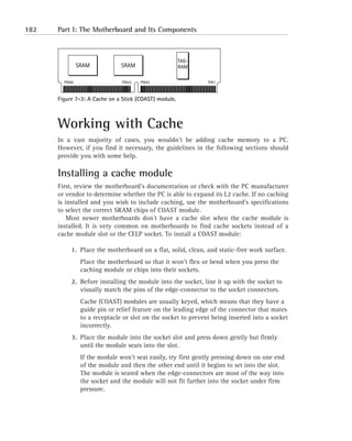
  • 1. 182 Part I: The Motherboard and Its Components TAG- SRAM SRAM RAM PIN80 PIN43 PIN42 PIN1 Figure 7-3: A Cache on a Stick (COAST) module. Working with Cache In a vast majority of cases, you wouldn’t be adding cache memory to a PC. However, if you find it necessary, the guidelines in the following sections should provide you with some help. Installing a cache module First, review the motherboard’s documentation or check with the PC manufacturer or vendor to determine whether the PC is able to expand its L2 cache. If no caching is installed and you wish to include caching, use the motherboard’s specifications to select the correct SRAM chips of COAST module. Most newer motherboards don’t have a cache slot when the cache module is installed. It is very common on motherboards to find cache sockets instead of a cache module slot or the CELP socket. To install a COAST module: 1. Place the motherboard on a flat, solid, clean, and static-free work surface. Place the motherboard so that it won’t flex or bend when you press the caching module or chips into their sockets. 2. Before installing the module into the socket, line it up with the socket to visually match the pins of the edge-connector to the socket connectors. Cache (COAST) modules are usually keyed, which means that they have a guide pin or relief feature on the leading edge of the connector that mates to a receptacle or slot on the socket to prevent being inserted into a socket incorrectly. 3. Place the module into the socket slot and press down gently but firmly until the module seats into the slot. If the module won’t seat easily, try first gently pressing down on one end of the module and then the other end until it begins to set into the slot. The module is seated when the edge-connectors are most of the way into the socket and the module will not fit farther into the socket under firm pressure.
  • 2. Chapter 7: Applying Cache Memory 183 Troubleshooting problems after installing new cache If you have a problem right after you’ve installed new or additional cache memory in a PC — perhaps the system won’t boot or fails immediately after the POST — more than likely the problem is that you’ve installed the wrong cache for your mother- board and chipset. On an existing system on which no changes have been made, a cache failure is extremely rare. Cache problems are generally the result of human intervention, such as the following: N Removing, replacing, or adding the wrong type of cache memory modules to a PC N Not setting the motherboard jumpers required to configure it properly N Dislodging something while installing the cache Here is a checklist of things to check if your PC fails after you have installed cache memory: 1. Before purchasing new cache memory — and definitely before installing it in your PC — check the motherboard’s documentation or visit the manu- facturer’s Web site to verify the type and mounting of the cache that it supports. 2. If you’ve replaced the old cache modules or added new cache to the sys- tem, check the motherboard’s documentation to see whether you need to change the settings of any jumpers. Newer PCs automatically adjust for new or additional cache, but some PCs configure the size or type of cache memory through jumper settings. 3. If you suspect that the cache is causing the problem, replace it with another cache module. If the problem goes away, you know that the original module was bad. This is probably the most foolproof troubleshooting step, provided that you have a spare cache module. 4. Disable the cache options in the PC’s BIOS configuration data. These options are accessed through the BIOS setup program. If the problem goes away after disabling the cache settings, you need to continue checking to determine the source of the error. 5. After the PC has been powered on for a few minutes, if you can’t hold your finger on the cache module for more than a few seconds because it’s too hot, the cache module itself could be bad.
  • 3. 184 Part I: The Motherboard and Its Components If the new module also gets too hot to touch after replacing the cache module, the motherboard is the likely problem. Re-verify that the cache is the right type for the motherboard; and if so, test the motherboard. 6. Ensure that you’re using the correct cache memory type for your system. If not, immediately remove and replace it. Remember to check and change, if necessary, the cache memory options in the BIOS settings. 7. Verify that the cache is installed in its mounting correctly and that it’s properly oriented and firmly seated in the socket or slot on the mother- board. 8. Check all drive and power supply connectors to see whether you acciden- tally unseated or dislodged one when installing the cache. 9. If you still cannot locate the problem, test the primary memory and check for any updated device drivers or software patches that have recently been installed. The problem could very well be coincidental and just happened to show up at this time. Adding cache didn’t improve system performance It is a commonly held belief that adding more L2 cache will improve system perfor- mance. But what if you add more L2 cache (assuming that the installation is correct and uses the right type of cache memory), and the PC doesn’t seem to be perform- ing any better than it did before the cache was added? If your PC already has 256KB of L2 cache and is already caching 90 percent or better of memory requests, the amount of improvement available is marginal, per- haps in the range of 5 to 10 percent. At the speed of the processor and SRAM, it’s very unlikely that you will notice this slight improvement. On the other hand, it could be that the cache isn’t installed properly and isn’t being recognized by the PC — and that’s what is accounting for the lack of improvement. Here are some steps that you can use to verify whether the cache is installed cor- rectly: 1. Check the BIOS display during the boot to determine how much cache is detected and reported. If it’s not the correct amount, check the cache modules to see whether they’re the right type for the motherboard or whether they’re installed correctly. 2. Check the motherboard’s documentation to see whether adding cache memory, especially more cache memory, requires jumpers to be changed. Then check the BIOS data for settings that might need to be changed.
  • 4. Chapter 7: Applying Cache Memory 185 3. If everything looks okay and checks out, use benchmark software (before and after the installation of the cache memory) and then compare the results. Even on the most efficient systems, you should see some improvement, no matter how small it might be. The processor disables the cache This problem is caused when a processor is installed on a PC, and the BIOS system is unable to properly recognize the processor. 1. Verify that the processor is properly seated in its socket. If so, this problem can usually be fixed by upgrading the BIOS. 2. Contact the motherboard or BIOS’ manufacturer to obtain a new BIOS ROM or flash BIOS upgrade file that supports the processor installed in the PC. Determining why adding RAM slows down the PC Some chipsets support the caching of over 64MB of primary memory. However, if the chipset, such as Intel’s Triton II 430HX (which supports caching of up to 512MB of RAM), is installed on a motherboard with only 8 bits of tag RAM, the system is limited to 64MB of caching. In order to cache more primary memory, more tag RAM must be added to those systems that can support the caching of more than 64MB of RAM. If the mother- board includes a chipset that supports higher levels of caching, it depends entirely on the motherboard as to whether additional tag RAM can be added. Check the motherboard’s documentation for the location, type, and specification of the tag RAM chips that are supported. Even if you add tag RAM, the size of your L2 cache will still control how much actual RAM you are able to cache. These two elements must be balanced to each other. Here are the steps that you should use to determine the problem caused by adding RAM to your system: 1. From the motherboard’s documentation, check to see whether the mother- board supports and has the 11 bits of tag RAM installed needed to cache up to 512MB of RAM. If the motherboard supports this much tag RAM but it’s not installed, check with the motherboard manufacturer for the specification of the chip
  • 5. 186 Part I: The Motherboard and Its Components that will provide this capability. Be sure to match the capacity of the tag RAM to the L2 cache and primary memory of your system. You might need to add additional L2 cache. 2. If your motherboard supports the additional tag RAM, it should have a chip socket into which a second tag RAM chip can be installed. The motherboard’s documentation or the manufacturer’s Web site should list the tag RAM chips that are compatible with the chipset and cache memory as well as any jumpers that need to be changed. Motherboards that have CELP slots for COAST modules might accept the type of cache module that incorporates an extra tag RAM chip. If so, when you add the extra 256K of cache, you also add the extra tag RAM needed to cache more than 64MB of RAM. Not all COAST modules have tag RAM included on them. Be very sure which modules are compatible with your motherboard and chipset. Remember that it isn’t the extra cache that lets more memory be cached; it’s actually the tag RAM that allows this to happen. Your only recourse if you can’t add additional tag RAM is to either live with only 64MB of cached RAM (regardless of how much RAM is on the PC) or to change out the motherboard with one that will allow you to increase the caching and with it improve your system’s performance. 3. If the tag RAM needed to exceed 64MB is installed, the problem is in mis- matched components, an improper configuration, or even the wrong components. Check the RAM and then the cache memory to find the possible causes for the slowdown. If RAM and cache memory check out, the cause is likely in the motherboard, its configuration, or an incompatibility of its components. Enabling the internal (L1) cache Virtually all microprocessors sold today include some amount of internal cache memory. A system’s internal cache is enabled or disabled through the BIOS setup program and the BIOS configuration data. You really have no reason to disable internal cache unless you’re trying to troubleshoot a caching problem.
  • 6. Chapter 7: Applying Cache Memory 187 1. Enter the BIOS setup area of your PC by using the key indicated by your BIOS during the boot process. 2. Check your BIOS settings to make sure that the internal cache is enabled and functioning. If for any reason you cannot enable the internal cache, you have a prob- lem with hardware configuration (among the motherboard, chipset, and processor). If you disable the internal cache, you can expect the perfor- mance of the PC to degrade. Enabling the external (L2) cache External cache is located between the processor and a PC’s primary memory. If your PC has L2 cache, it should be enabled. Like the L1 (internal) cache, L2 cache is also enabled through the BIOS settings. If you cannot enable the L2 cache, you have a problem with the PC’s hardware configuration, either in the external cache itself or on the motherboard.
  • 7.
  • 8. Part II The System Case and Power Supply CHAPTER 8 The System Case CHAPTER 9 Powering Up the PC
  • 9.
  • 10. Chapter 8 The System Case IN THIS CHAPTER The PC’s case is largely taken for granted. It is definitely not high on the list of components that you deal with the most. However, in spite of the fact that the sys- tem case has only one or two active components — namely, the power supply and the front panel — it plays a major part in the overall operation of the PC. In this chapter, I discuss N The construction and purpose of the PC’s case N The components of the PC case N Dealing with system case issues N Installing a motherboard in a PC case THE SYSTEM CASE consists of six major components. Each of these major compo- nents is covered in the sections that follow. Dissecting the System Case The six major components of the case are shown in Figure 8-1. These components, which I cover in depth in this chapter, are N Power supply N Cover N Chassis N Front panel N Switches N Drive bays 191
  • 11. 192 Part II: The System Case and Power Supply Cover Switches Power supply Drive bays Chassis Front panel Figure 8-1: The major components of the system case. Although not actually a physical component in the hardware sense, a very important part of a PC’s case is its form factor. A case’s form factor describes its shape, the way that its components fit together, and its size. Form factors apply to the case and the power supply and motherboard that fit into it. These three compo- nents must fit together to provide protection, power, cooling, safety, and of course, function. Therefore, it’s very important that all three components have the same or compatible form factors. Building the Case of the Case The PC case does much more than just sit on the desk or floor holding the PC’s parts or holding up the monitor, performing a number of very valuable functions that are for the most part taken for granted. The case also provides the aesthetics of the sys- tem; it provides the physical structure of the PC; and it provides protection and cooling to the electronic components and other devices mounted inside its covers. The PC’s case isn’t just another pretty face; it has a very important role to play in the overall function of the PC. PC cases come in all sorts of sizes, shapes, colors, and animals, see those shown in Figure 8-2. The variances in size and shape are driven primarily by the form fac- tor of the case, but increasingly, case designers are adding color, new plastic and metal materials, and even character faces to case designs in an attempt to make them less boring and more appealing to a wider audience. The cases shown in Figure 8-2 represent a wide variety of case types and form factors from a number of different case manufacturers.
  • 12. Chapter 8: The System Case 193 Figure 8-2: PC cases come in all sizes, shapes, and faces. Sorting out the case components As shown in Figure 8-2, not all system cases are the same size or shape, but they all contain virtually the same components and parts. Here is a list of the most common system components found inside the PC’s case: N Chassis: This is the skeletal framework that provides the structure, rigidity, and strength of the case; it also plays a major role in the cooling system of the case. N Cover: The cover, along with the chassis, plays an important role in the cooling, protection, and structure of the PC. N Drive bays: Beginning with the PC XT, disk drives with removable media have been mounted in the case so that they can be accessed on the front panel. Typically, the drive bays house 5.25" and 3.5" disk drives, such as floppy disks, CD-ROMs, DVDs, and removable hard drives. N Front panel: In addition to providing the PC with its looks and placement of the power and reset switches, the front panel provides the user with information on the PC’s status, is a means of physically securing the PC, and can be the starting point for removing the case’s cover. N Power supply: As you are undoubtedly aware, the power supply is a very important component of the PC in general and not just to the case. The power supply’s primary job is to rectify (convert) AC power into DC power
  • 13. 194 Part II: The System Case and Power Supply for use by the PC’s internal electronics. However, it also houses and pow- ers the main system cooling fan. Power supplies are not discussed in detail in this chapter other than to discuss how they fit in a case and their form factors. See Chapter 9 for more specific information on the power supply. N Switches: Most newer systems have their two main switches (the power switch and the reset switch) on the front panel. If the power switch is not on the front panel, it’s probably located either in the right-rear corner or near a corner on the back of the PC. CHASSIS Beneath the sheet metal or plastic exterior skin of a PC’s case is a metal framework that provides the structural framework of the PC. Just like the interior of a building or the human skeleton, the PC’s chassis (pronounced chass-ee) provides the frame on which all other parts of the PC mount, attach, or hang. As shown in Figure 8-3, the sheet metal of the chassis gives the PC its shape, size, rigidity, strength, and the location of its components. Figure 8-3: The chassis of a desktop PC. CONSTRUCTION The frame of the PC must be a rigid structure. Many of the components and devices in the PC cannot withstand being flexed, especially when they’re operating. This is especially true of the motherboard. If the frame can twist and bend, the fragile electronic traces on the motherboard or other components could break, the mother- boards mountings could slip or break, or expansion cards could be partially ejected from their slots — any of which could damage or destroy the motherboard or expan- sion cards. In these situations and many others, the rigidity and strength of the case’s chassis is one of its key attributes. When evaluating a system case, assure yourself that a chassis’ structural framework is constructed strongly and can pro- tect the components mounted to and in it.
  • 14. Chapter 8: The System Case 195 Not that you would usually know, but the frame of the PC chassis should be con- structed from a heavy-gauge steel that’s at least 18-gauge steel; 16-gauge steel is even better. Less-expensive cases might use lighter-gauge steel or aluminum. Nothing is wrong with a lighter metal or aluminum case, provided that the case is reinforced in key supporting locations with heavier-gauge steel. Be wary of bargain cases made of lightweight aluminum because these cases are much too pliable and can flex too much when being moved or lifted, causing the problems listed earlier. The few pounds of the PC’s total weight that you save by buying a lighter- weight case made of lighter-gauge metals are definitely not worth the potential for problems that a flexing or bending case can cause. Something more to consider when choosing a case for a PC is its internal design and layout. Where the crossbeams are located in relationship to where the mother- board, power supply, disk drives, and other components mount can pose problems later when you’re trying to repair or upgrade the PC. COVER Of the many ways to attach the cover to the chassis, the most common method is to use a few screws, but you’ll also see screwless or tool-less systems where the case covers literally hang on the chassis by using keyholes or slide-and-lock features. However the cover attaches to the chassis, it’s extremely important that it has a snug and secure fit. The case’s cover is engineered to provide the best possible airflow dynamics. It is also a key component of the radio frequency interference (RFI) and electromagnetic interference (EMI) protection designed into the system. If your PC is by the Federal Communications Commission (FCC) (and virtually all PCs are), the case was designed to be a major part of the radio frequency (RF) emissions control of the PC. One of the risks in having a cover that doesn’t fit tightly and securely without gaps or loose parts is that it can emit RF signals and thus affect other devices near it. Sometimes, though, the problem with loose or badly fitting case parts can just be an annoying rattle from the escaping airflow breeze. Many methods are used to attach the outer cover of the PC to the chassis. The most common is that the cover is attached with screws to the front, sides, and rear of the chassis. Rarely would you completely remove all sections of the PC’s cover from the chassis. Normally, only the side (tower) or top (desktop) is removed to pro- vide access inside the case. The following sections discuss the more common styles of covers and how they are attached and removed from the chassis. LEGACY DESKTOPS The desktop PC, an example of which is shown in Figure 8-4, is by far the most common of the case designs. There are desktop models for nearly every form factor
  • 15. 196 Part II: The System Case and Power Supply (see “Factoring in the case form” later in this chapter), including the earliest PCs (such as the PC XT and the PC AT systems), the more common PCs (such as the Baby AT and ATX systems), and the newer LPX slimline systems. For the most part, older systems have a U-shaped piece that incorporates the covers for the top and sides of the PC. This piece is attached to the chassis with four or five screws to the rear panel. It is removed by either sliding it all the way back or forward off the PC or by sliding it back a bit and then lifting it straight up. The benefit of this cover design is its simplicity, but you must be careful when removing or replacing it that you don’t snag power and data cables, expansion cards, or disk drives and dislodge or damage them. Monitor System unit Keyboard Mouse Figure 8-4: A desktop PC. LEGACY TOWERS Of the many types of tower cases (see Figure 8-5), the most common tower designs are typically the full-size AT, Baby AT, or ATX case. On these cases, the cover is a U-shaped piece with very long sides that fit down and over the frame of the tower’s case. This cover is attached to the rear of the case with four to six screws. To remove this cover, the screws are removed; then the cover is either lifted straight up and off, or it slides back a bit and is then lifted up and off. TOOL-LESS CASES Many brand-name PCs feature a case that has one or two large knobby screws on the back panel of the case. This case design is called tool-less because you should be able to remove and replace the screw with your fingers without a screwdriver or other tools. (See Figure 8-6.) The cover pieces are held firm by spring clips that apply pressure to chassis points to hold the cover pieces in place.
  • 16. Chapter 8: The System Case 197 Figure 8-5: A PC in a mid-tower case design. Figure 8-6: A tool-less case design is secured with one or more large screws. SCREWLESS CASES This type of case cover features several individual cover pieces, generally one piece to a side. The key to removing this type of case cover is to remove the locking panel (usually the front panel) to unlock the remaining panels of the case. The front panel is attached by a spring clip and is pulled up and lifted off one or more hook-like tabs built into the chassis, as shown in Figure 8-7. After the front panel is removed, the top is first removed (typically by lifting it straight up) and then the sides, one at a time, if needed.
  • 17. 198 Part II: The System Case and Power Supply Figure 8-7: Removing the front panel of a screwless case. Some screwless cases have a cut-in indentation at the bottom of the front panel that can be used to grasp the edge of the panel to pull it up. On others, where no such handhold is provided, you might need to use a small screwdriver or pry tool to pull the front panel up enough to gain a grasp of its edge. One minor drawback to a screwless case is that you have several case parts to track instead of just the one-piece desktop case. RELEASE-BUTTON CASES This case design, which is common on Compaq desktop models, is removed by pressing spring-release buttons located on the front or rear of the PC. After press- ing the release buttons, the cover (which includes the front, rear, top, and sides of the cover) lifts straight off the case. A case with a similar design is called the flip-top case. This case design also uses release buttons to unlock the cover, but instead of the entire top lifting off, the top cover tips up like a top-loading washer. If you need to remove the entire case for some reason, strategically placed screws can be removed to release the entire cover.
  • 18. Chapter 8: The System Case 199 FRONT-SCREW CASES On this case design, the screws that hold the cover on the PC are located on the front panel and are usually hidden behind sliding tabs or a snap-on panel. Removing the screws (and possibly some on the rear panel as well) allows the case to be pulled forward and off the case. Scanning the front panel The primary purpose of the front panel (or bezel) is to cover up the front end of the chassis, but because it’s the part that the user looks at most of the time, efforts have been made to make it useful and appealing. Some PCs feature doors and snap-on panels to mask disk drives, the power and reset switches, and even the light-emitting diodes (LEDs) on the front of the PC. Typically, doors on the front panel are a characteristic of larger PCs and network servers. Figure 8-8 shows a WTX server with two doors: one for the removable dri- ves and the other to cover the normal parts of the front panel. This computer also features a key lock for the doors to provide a small amount of security. See “Factoring in the case form” later in this chapter for information on the WTX, ATX, and other PC case form factors. Figure 8-8: A WTX form factor computer with two front panel doors.
  • 19. 200 Part II: The System Case and Power Supply STATUS LEDS Most PCs have LEDs on the front panel to show the status and activity of certain parts of the system. Typically, two LEDs are used: one that is lighted when the power is on, and one that indicates when the hard disk is being accessed. Other LEDs are visible on the front of the PC, but they are generally part of the disk drive installed in a drive bay. Very old PCs also have a Turbo LED that indicates that the system is in Turbo mode, which raises the processor speed of a PC. Turbo systems are generally obsolete now. Here is a quick overview of the front panel’s LEDs: N Hard drive LED: When the disk drive is seeking, reading, or writing data, this red, orange, or amber LED is lighted and flashes. The speed with which the hard drive LED flashes is a good indicator of how busy your PC is. Typically, this LED is wired to the motherboard or the disk controller or adapter, which means that it reflects the activity of all disk drives on the PC. N Power LED: This LED is typically green in color and is illuminated when the PC’s power is on. N Turbo LED: If present, this yellow LED indicates that the PC is in Turbo mode. The Turbo button was used on very early systems as a part of a backward compatibility strategy. There wasn’t a lot of software available to begin with, and when the 8 MHz systems were released, many people had a fair investment in software that would run only in the older 4.77 MHz, or PC XT mode. Normal mode on these systems, 286 and 386 processors, was Turbo mode. However, when the Turbo button was released, two things happened: The PC processor was slowed to 4.77 MHz, and the Turbo LED was turned off. FRONT-PANEL SWITCHES Nearly all PCs now have at least one main switch (usually the power switch) on the front panel of the PC. Some older designs have two switches: the power switch and a reset switch. Figure 8-9 shows a PC front panel with its power switch. POWER SWITCH On older PCs, the power switch was a part of the power supply and extended through the case wall on the right-rear corner of the PC. More recently, the power switch is on the front panel. On Baby AT systems and before, the power switch located on the front panel is not a switch in the sense of a physical on/off switch. It is actually a proxy switch that transfers a press on the front panel switch to the actual power supply switch located on the back of the front panel and wired directly to the power supply. Newer systems, such as the ATX, NLX, and LPX form factors, have an actual power switch on the front panel, but instead of being wired to the power supply, the switch is now electronic and is actually connected to the motherboard. On these systems, you don’t turn the computer on or off with the power switch; rather, push- ing the power button sends a request to the motherboard to power off the PC.
  • 20. Chapter 8: The System Case 201 Figure 8-9: The power switch on a PC’s front panel. RESET BUTTON Although disappearing from PCs largely to prevent accidental resets, the reset switch, also referred to as the reset button, performs a hardware reset when pressed. This provides the user with a means of restarting the PC should it halt and not respond to normal shutdown or restart commands. Using the reset button is better than powering the PC off and back on, which can sometimes result in POST or BIOS errors. On some older PCs, the reset button was placed on the front panel and was easily accessed, which caused more than one unexpected system reset. Newer cases, if they feature a reset button, recess the button to prevent inadvertent resets from taking place. A few manufacturers have moved the reset button to the back of the PC, which is safer yet. Some manufacturers, such as Gateway, don’t include a reset button on their systems. Resetting the PC must be done via the keyboard (by pressing Ctrl+Alt+Del) or by using the operating system’s restart process. TURBO BUTTON As I explain in the earlier section “Status LEDs,” the Turbo but- ton and its functions are now obsolete except on 286 and early 386 computers. If your front panel has a Turbo button, chances are that it’s not connected to any- thing; to avoid any possible problems, you should never press it. KEYLOCKS Although not technically a switch, some cases have keylocks on their front panels. The two types of keylocks available on PC front panels are a front panel door lock and a keyboard lockout. N Front panel door lock: If the front panel of your PC has one or more doors, it might also have a door lock either on the door or on the front panel. When the doors are closed and locked, curiosity seekers are pre- vented from accessing the drives behind the doors. However, because the
  • 21. 202 Part II: The System Case and Power Supply doors are made of plastic and can be pried open easily, this feature should not be used or thought of as a means to secure the system. N Keyboard lockout: When locked, this type of keylock sets a logical condi- tion on the system that locks out the keyboard, thus preventing anyone from using the PC. When someone attempts to use the PC while this key- lock is locked, an error message is displayed on the monitor that in effect says that the system is not available for use. While this keylock is locked, the PC will not boot. The keyboard lockout keylock was intended to be a first-level of security for PCs in large offices and work areas. The keys for a PC keylock are usually round, and many manufacturers use the same key for all their systems. Thus, the security that keylocks can provide is limited. Anyone with a screwdriver can open the case and disable the lock; and on some cases, you don’t even need the screwdriver. If your case has a keylock or a front-panel door lock, be sure that it also has keylock keys. Typically, you’ll get two of each key. If you plan to use them, store one of the keys in a safe place so that if you lose the first one, you can still unlock your PC. DRIVE BAYS Since the PC AT, you have been able to decide the number and type of disk drives in your computer. As long as the power supply and cooling system would support them, you could add floppy disk drives, hard disk drives, CD-ROM drives, tape dri- ves, and more to your PC. Generally, drives are installed in the drive bays provided on virtually all PC case designs and form factors. Figure 8-10 shows a desktop computer with its drive bays exposed. This system, an ATX case, provides three 5.25" half-height drive bays, two 3.5" one-inch high drive bays, and two 3.5" drive bays hidden inside the case. Originally, disk drives required a drive bay that was 3.5" in height. As technol- ogy was able to reduce the size of the overall drive, this height was cut in half, and now most of the drive bays available for 5.25" devices are less than 2 inches in height and are called half-height.
  • 22. Chapter 8: The System Case 203 3.5-inch drive bays 5.25-inch drive bays Figure 8-10: The drive bays of an ATX desktop chassis. INTERNAL VERSUS EXTERNAL BAYS As indicated in the previous paragraph, the two types of drive bays are external and internal: N External drive bays: These drive bays are actually internal to the case and chassis, but they can be accessed externally, which is how they get their name. External drive bays are typically used for drives that have remov- able media, such as floppy disks, CD-ROM, DVD, tape drives, and the like. N Internal drive bays: Internal bays are completely inside the system case and have no access from outside the chassis, as shown in Figure 8-11. These bays are designed for devices, primarily hard disk drives, with no need for external exposure. Simply put, internal drive bays are for hard disks. Internal drive bays Figure 8-11: Internal drive bays inside a chassis.
  • 23. 204 Part II: The System Case and Power Supply Internal devices can be installed in external bays. Before internal bays were common, hard disk drives were installed in the external bays (the only kind available), and a solid faceplate was put over the external opening of the bay to hide the drive. MOUNTING RAILS You have two methods to mount a device in a drive bay, whether internal or exter- nal. One way is with the use of drive rails, and the other is mounting the device directly to the walls of the drive bay. N Drive rails: These two strips of metal are mounted to the sides of the disk drive. With the drive rails attached, a device is placed into the drive bay with the rails sliding into notches or facets on the sidewalls of the bay. The device is suspended from the rails, which are then secured to the walls of the bay. N Sidewall mounting: This method, used in most newer cases, involves attaching the disk drive to the sidewalls of the drive bay. Screws are placed through holes in the sidewall that match the standard placement and spacing of pre-threaded holes on the sides of the disk drive. The drive is solidly attached to the chassis. DRIVE CAGES A newer feature on system cases is snap-in cages for internal drive bays, like those shown in Figure 8-11. To install a hard disk in an internal cage, you remove the cage, install the drive, and then snap the cage and drive assembly back into place. If you use a cage to install an internal drive, think ahead to the cables and connec- tors that might be added later and the process that will be needed to remove the drive for servicing. STYLING THE CASE The two basic styles of PC cases are the tower case and the desktop case. Figure 8-12 shows a family of PC cases that includes both tower and desktop styles. The tall, thin one are the tower case style, and the flat, boxy one is the desktop case style. At one time, they were actually very much alike. In fact, the tower came about when people tried to save space by turning their desktop PCs on their sides. Today, these case styles are very distinctive with their internal designs, the way the case is attached, and the features that each supports.
  • 24. Chapter 8: The System Case 205 Figure 8-12: A family of PC cases. TOWER VERSUS DESKTOP Which case style is right for a particular setting really depends on how it is to be used — and frankly, the setting itself. Tower cases are designed to sit on the floor or large shelves. Desktops are designed to sit on desks, which is why they’re called desktops. A tower case does free up desktop space, but if the space on the floor is limited, the case can be in the way, kicked, or knocked over. The desktop cases of today are a lot smaller (shorter and narrower) than they were when the PC was first moved off the desktop. The two case styles really aren’t interchangeable, despite the claims of the ven- dors selling conversion kits. Turning a desktop PC on its side changes the orienta- tion of the removable media drives: namely the CD-ROM, DVD, and other such drives. If you wish to move from a desktop to a tower, or vice versa, I recommend that you purchase the appropriate case and convert the PC into the new case. DESKTOP CASES Although this case style is not as popular in recent years as it once was, desktop cases are still generally available from most PC manufacturers and resellers. Because it also doubles as the base for the PC’s monitor, the desktop case is actually more space efficient than the mid-sized tower models. Some tower styles are small enough to sit on a desktop but cannot hold the monitor and thus end up using more space than a desktop unit would. In some situations, the desktop PC is better suited than a PC in a tower case, primarily where floor space is limited. Until very recently, the desktop case style had been the unofficial standard for PC cases. The first PCs, the PC XT and PC AT, were desktop units. The desktop cases of today are smaller than those of the original PC AT and its clones. The common desktop form factor is the Baby AT and now the LPX low profile case, which is also known as the pizza box case. Newer slimline cases, such as the NLX (which was designed to replace the LPX), are becoming more popular.
  • 25. 206 Part II: The System Case and Power Supply TOWER CASES In today’s market, the tower case style is far more popular than the desktop case style mainly because a tower case can sit under a desk to free up workspace on the desk, thus providing more space than the desktop inside the case for upgrading the PC. Three of the more popular tower case sizes are the mini-tower, the mid-tower, and full-tower. Variations on these sizes exist between manufacturers because no standard sizes are associated with these three case styles. Figure 8-13 shows a tower case family from one vendor. What one vendor calls a mini-tower, another might call a mini- mid-tower. When buying a PC, first pick the brand that you wish to buy (if you have a preference) and then look at the form factor, sizes, and styles of cases avail- able. With a tower case, the primary difference between models is usually the number of external drive bays and the size of the power supply. As the number of external bays increases, the case gets taller, and usually the power supply gets more powerful. Figure 8-13: A family of computer cases showing a full AT tower on the left down to an ATX mini-tower on the right.
  • 26. Chapter 8: The System Case 207 Here are the popular variations of the tower case style: N Full tower: Full tower cases are the largest standard PC cases available. They offer the most of any case style in the way of expandability, typically having three to five external drive bays and a few internal bays as well (see Figure 8-14). A full tower case will normally have a high-end power supply under the assumption that the case will be filled with devices. This style of case is popular among high-end users and for servers. Figure 8-14: A full tower case featuring external drive bays. N Mid-tower: A mid-tower case is a slightly shorter version of the full tower case. This particular size seems to vary the most among manufacturers, but within a single manufacturer’s line, it represents a good compromise of size and price. For example, the mid-tower case shown in Figure 8-15 pro- vides external drive bays and can accommodate either ATX or full AT form factor system boards, which should be room enough for most applications. N Midi-tower: This case style exists somewhere between the mid-tower and the mini-tower cases. By definition, a midi-tower is smaller than a mid-tower and larger than a mini-tower. However, what you will typically find adver- tised as a midi-tower is either a small mid-tower or a large mini-tower — or as available from one manufacturer, a mini-mid-tower. Regardless of the case’s style name, if it fits your needs, it’s the right one. N Mini-tower: This case size is probably the currently most popular. It provides slightly more expansion capacity than desktop cases and is small enough to sit on a desktop next to the monitor. If you’re considering converting a desk- top case to a tower, this would be an excellent and economical choice because they run around $25 or less. Figure 8-16 shows a mini-tower case.
  • 27. 208 Part II: The System Case and Power Supply Figure 8-15: A mid-tower case. Figure 8-16: A mini-tower case. RACKMOUNT CASES Another type of case that has usage in special purpose or networking applications is the rackmount case. This case is designed to be attached to the rails of a rack- mount cabinet or a rackmount stand. Figure 8-17 shows a rackmount PC with its cover opened.
  • 28. Chapter 8: The System Case 209 Figure 8-17: A rackmount PC case. Factoring in the case form The form factor of a PC case defines its style, size, shape, internal organization, and the components that are compatible with cases of that form factor. Computer form factors define a general standard for compatibility for the system case, the mother- board, the power supply, the placement of input/output (I/O) ports and connectors, and other factors. The three most popular types of case form factors are the Baby AT, ATX, and NLX. N Baby AT: Although virtually obsolete by today’s standards, the Baby AT form factor still has a very large installed base from its popularity in past years. N ATX: The ATX form factor is the de facto standard for motherboards, power supplies, and system cases. Virtually all Pentium-based systems use the ATX form factor. N NLX: The NLX form factor, also called slimline form factor, is popular for mass-produced desktop systems. Here is a quick look at some of the other form factors that have been used or are still in use for system cases: N PC XT: This form factor was used on the original desktop PCs: the IBM PC and its successor, the PC XT. The case was made of heavy-gauge steel and had a U-shaped case that was fastened on the rear of the PC and was removed over the front of the case. The power supply had 130 watts (only 63.5 watts on the PC) and was located at the rear of the case with a power switch that protruded through a cutout on the case.
  • 29. 210 Part II: The System Case and Power Supply N AT: The IBM PC AT, although not much different on the outside than its predecessors, was quite different on the inside. The motherboard and power supply (which was much larger) were repositioned inside the case. The AT quickly became the standard form factor among manufacturers; all subsequent form factors, whether desktop or tower, are based in one way or another on the AT. N LPX: Although never officially accepted as a standard form factor, LPX is the oldest of the low-profile form factors. Over the past ten years, it has been one of the most popular slimline form factors sold. Slimline cases are a little shorter than Baby AT or ATX cases. This is achieved by moving expansion cards to a riser board that mounts horizontally in the case instead of vertically, thereby saving inches of height. N MicroATX and FlexATX: These two ATX-based form factors define speci- fications for smaller versions of the ATX motherboard. Micro-ATX and FlexATX do not define case form factors, but manufacturers are designing cases to take advantage of their smaller footprint. These form factors are intended for PCs targeted to the mass market and home users. N WTX: The W stands for workstation, and the WTX is a form factor intended for high-performance workstations and servers. This form factor defines a modular case that features a motherboard that’s twice the size of an ATX motherboard. A WTX case features space for high-capacity, redundant power supplies, removable panels for easy access to compo- nents, a large number of hard drive bays, and support for multiple cooling fans. Refer to Figure 8-8 for a WTX form factor computer. For more information on PC form factors as they relate to motherboards and power supplies, see Chapters 1 and 9. SYSTEM CASE FEATURES When you buy a system case, like the one shown in Figure 8-18 without its covers, it will include some pre-installed components and features, which are usually the optional pieces that conform a generic case to fit a particular form factor and your particular requirements. Because several of the form factors are very close in their size and component placement, manufacturers make cases that can be used with a number of form factors. Applying such items as an I/O template, the appropriate power supply, and motherboard mounts turns the generic case into a custom case that’s just right for your needs.
  • 30. Chapter 8: The System Case 211 Power supply Power cord plug Fan grill External drive bays Front of chassis Chassis rear I/O ports Internal drive bays Air venting I/O template Auxiliary fan Expansion slots Figure 8-18: An ATX case and its components. I/O TEMPLATES Each motherboard form factor also defines the location and placement of the ports used for such input/output devices as the keyboard, mouse, printer, and others. For the most part, these ports are connected either directly or indirectly to the mother- board. Directly connected ports are physically mounted on the motherboard. The case must accommodate these ports with a hole in the right shape and place so that the port can be accessed through the case. Indirectly connected ports mount to the case and are attached to the motherboard with a cable. Either way, the case has to either be manufactured with the portholes already in place or provide an adapter for this purpose. Older form factor cases, such as the PC XT, AT, Baby AT, and the LPX, were manufactured with holes cut into the rear panel of the case to match a particular form factor. However, to make cases more flexible and allow them to service more than a single form factor, manufacturers devised I/O templates, which can be snapped into a case to provide the I/O port pattern desired. Figure 8-19 illustrates what the templates look like out of the box. A current trend among case manufacturers is to leave a punch-out or knockout slug in the I/O ports on the I/O template (as shown in Figure 8-19) and the expan- sion slots. If you’re not using a port or slot, you can leave the slug in place. However, be sure that you ask and understand how this affects the case cooling before assuming that it’s a part of the overall case design.
  • 31. 212 Part II: The System Case and Power Supply Figure 8-19: I/O templates with the port slugs in place. Supplying power Most (not all) system cases come with a power supply (see Figure 8-20) matched to its form factor. Power supplies are not a part of the case even though they’re gen- erally sold together as one assembly. When buying a PC case, be sure that a power supply appropriate for your application is included — or that a power supply is not included, as you wish. Many case manufacturers sell their cases à la carte, and you can select the options and power supply to meet your needs. See Chapter 9 for more information on power supplies. Auxiliary fans The main cooling fan in the PC is in the power supply, which is an important rea- son why you should match the power supply to the form factor of the motherboard and case, in that order. Many newer case form factors provide a location for an auxiliary or supplemental fan to help cool the inside of the PC. Typically, the loca- tion of the auxiliary fan, if available, is on the opposite front or back panel from the main cooling fan, as shown in Figure 8-21.
  • 32. Chapter 8: The System Case 213 Figure 8-20: A power supply can be purchased separate from the system case. Main fan Auxiliary fan Figure 8-21: The locations of the main cooling fan and an auxiliary fan on an NLX case.
  • 33. 214 Part II: The System Case and Power Supply Lights, sound, and the connecting wires The other components of a PC case are the LEDs, the system speaker, and the wiring that connects these two items, plus a few more, to the power supply and motherboard. N LEDs: Most PC cases include at least two LEDs that are used as indicators for the power and hard disk. Although fairly uncommon today, some cases might have other LEDs for Turbo mode and the CPU’s activity level. N Front panel wiring: On the back of the front panel (near the system speaker, the LEDs, and the keylock) should be a small bundle of multi- colored wires that connect these items to the motherboard and perhaps each other. The LEDs should have two wires: one that’s either black or white (ground) and one that’s some other color (positive). N System speaker: The system speaker isn’t intended for stereo sound or to play your audio CDs. Rather, it’s only meant to be a basic means of com- munication between the motherboard, BIOS, chipset, processor, and other system components and the user. About the best it can do is sound beep codes during the boot and other monotone sounds by some application software. The system speaker is normally mounted inside the case near or on the front panel. On a new case, it might be included loose (not pre- mounted), allowing you to place it where you wish. Cooling vents Although this might seem obvious, air must have a means to get into or out of the system case. Usually, the case should have a grouping of small vent holes, cuts, lou- vers, or the like. Because of its larger airflow, a bigger case cools the internal com- ponents better than a smaller case, but both must still have a way to vent the case. You can assume that any case you buy from a reputable manufacturer is engineered properly for cooling and ventilation. When assembling a system case and its components, be aware of where the vents are and take care not to block them.
  • 34. Chapter 8: The System Case 215 Mounting the motherboard If you’re buying a new case, it should come with mounting hardware. These pieces normally come with the case and not the motherboard. Make sure that you have the appropriate mounting hardware, or your PC building project will come to a halt! The exact hardware included varies greatly and depends on what the manufacturer decided to include in the case, but you’ll generally find some combination of the following: N Fixed mounting hardware: Some cases already have their mounting hard- ware fixed (meaning soldered or welded) in place to match the mounting holes of a motherboard of the same form factor as the case. This is intended to save you time, but if you ever want to move to another form factor motherboard, you’ll need a new case. N Metal standoffs: Metal standoffs are rarely used because they’re a bother to work with and they cost more than the plastic type. However, if your case has threaded holes in place of mounting slots, these brass hexagon spacers need to be used. The standoff has screw threads on one end and a threaded screw hole on the other end. The screw end is screwed into the case, and then the motherboard (along with some insulating Teflon, Delran, or paper washers) is attached to the other end with a screw. The washers are placed between the standoff and the motherboard and between the motherboard and the screw. This keeps the metal-edged mounting hole from contacting the screw and standoff and preventing it from shorting the board. N Plastic standoffs: These small plastic parts are also called spacers, risers, and sliders. The standoffs used inside the case to mount the motherboard are typically small plastic legs (see Figure 8-22) that snap into the mount- ing holes on the motherboard and then slide into the mounting slots on the case. In addition to anchoring the motherboard in place, the standoffs keep the motherboard from contacting the system case and grounding or shorting itself.
  • 35. 216 Part II: The System Case and Power Supply Figure 8-22: The plastic standoffs used to mount a motherboard in a PC case. Dealing with Case Issues Problems directly related to the case itself are rare, but when they do occur, they typically involve the fan, power supply, wiring, or improper installation of compo- nents or devices. The sections that follow deal with the problems and activities that you might encounter when working with a system case. Preparing a case for a motherboard If you’re building a new PC from the ground (or from the case) up, you must first perform these steps to prepare the case to accept the motherboard. 1. Open the case by removing the cover piece that exposes the inside of the case. The case should come with a manual that has instructions and (hopefully) illustrations on how this is done. 2. The case should have one or more plastic bags of parts that you’ll need to assemble the case and to mount other system components in the case. At minimum you should have I Mounting hardware for the motherboard — either plastic or metal stand- offs or spacers. I Metal slot inserts that are used to close any unused expansions slots in the back of the case. These might already be installed. I Rubber feet for the bottom of the case, which might already be attached.
  • 36. Chapter 8: The System Case 217 I Drive cages (if the case supports them) or drive rails. I A power supply AC cord, if a power supply is included with the case. If not, you’ll need to install one before installing any other components to the case. 3. Use compressed air to blow out any packing materials or dust in a new case. 4. Check the power supply for apparent damage, and then check the cables, fan, and its casing. Make sure that the voltage selector is set appropriately for your power source. 5. Install the feet, if they’re not already installed. After the motherboard is installed, this step might not be as easy as it is now. 6. Install the slot inserts into the expansion slots. This step can wait until after the expansion slots are installed, if you prefer. 7. Install any auxiliary fans that you wish to use, if the case supports them. 8. If the case has a removable or swing out motherboard panel, remove it (see the case’s documentation) so that you can install the motherboard to it outside of the case. The front panel LEDs don’t light up If the front panel LEDs don’t light up, the problem is probably that the front panel’s LEDs aren’t connected or have been connected incorrectly. The good news about connecting the front panel LEDs is that if you do it wrong, all that will happen is that they won’t light up. Front panel LEDs will have a ground wire. The ground wire is either a black or white wire attached to a one-pin push-on connector that’s connected to the motherboard’s LED ground connector, which should be marked on the mother- board. The positive wire is some other color (perhaps red, blue, or green) that’s con- nected to the motherboard’s LED connector. It, too, is a one-pin push-on connector. These connectors are usually located along the front or side edge of the mother- board. Check the motherboard’s documentation for the location of these connectors if you cannot find them. If the LEDs don’t light up, try reversing the wires of the bad LED or exchanging the wires of two or more of the LEDS. Chances are that you’ll find a combination that works.
  • 37. 218 Part II: The System Case and Power Supply No sound is coming from the system speaker If no sound is coming from the system speaker, the speaker has probably not been connected to the motherboard or the connectors are plugged in incorrectly. Like the LED wires covered in the previous section, the system speaker has two wires that connect to the motherboard with either a single 4-pin connector or two 1-pin connectors. If you get the connectors on backwards or off to one side or the other, the worst that can happen is that it just won’t work. You won’t damage the speaker by connecting it incorrectly. Also, the speaker could be defective. If the wiring looks right and checks against the documentation, try using the speaker in a new PC or using a new speaker in this PC. The reset button does not restart the PC If the PC has a reset button, it should restart the PC when pressed. If nothing hap- pens when you press this button, the wires that connect the reset button to the motherboard were probably not installed, were not installed properly, or have come loose — or you have a problem with the motherboard that you might just have to live with. Check the motherboard’s documentation to verify the location of the connector for the reset button’s wiring and verify that it’s properly connected. The power on/off button does not work If the power on/off button doesn’t work, make sure you know which case, mother- board, and power supply form factors you have before you do very much to trou- bleshoot this problem. ATX form factor motherboards and power supplies pass live AC through to the on/off switches that are on the front panel, and getting these connections wrong can be dangerous to the motherboard and yourself. Follow the instructions in the motherboard’s documentation for connecting these switches or that in the case’s documentation for the front-panel switches. An ATX power supply doesn’t have a front-panel cable and might not have an on/off switch of its own. An ATX motherboard controls the power supply with a logic cir- cuit that turns it on and off. The switch on the front panel sends a signal to the motherboard, which relays it the power supply. The ATX motherboard always has at least 5 volts of standby power on it, even when the power supply is off. Setting the monitor on the system case halts the PC If the PC freezes, reboots, or powers off whenever you set anything (especially the monitor) on top of the case, chances are that something is causing the motherboard to touch the case and short out, which should happen soon after the system boots, if it will boot. The weight of the monitor or other object is apparently too much for the case’s structure, thus causing it to bend or flex.
  • 38. Chapter 8: The System Case 219 Here’s another possibility: In some weird way, the monitor (or whatever else you are putting on the case) is changing the airflow inside the system case and causing the processor or motherboard to overheat. The processor and chipset will shut down when they approach operating temperatures outside their normal ranges. Check to see that the monitor is sitting squarely in the center of the case or over the main structural points of the case. Avoid setting the monitor off to one side or on a corner of the case. Then try operating the system without the monitor on top of the case. If it works fine, the case just isn’t strong enough to hold the monitor, especially if it’s a large 17" monitor or larger. If workspace is an issue, several monitor stands are available that function like bridges placed over the PC’s system unit to hold up the monitor. You can also place the monitor on a swing arm mount that connects to the desk. If the problem continues, investigate a cooling issue or perhaps a faulty power supply. Try rearranging the cables inside the case to open up some airflow or perhaps, if the case supports it, add an auxiliary fan.
  • 39.
  • 40. Chapter 9 Powering Up the PC IN THIS CHAPTER Because a computer is an electrical device and digital logic circuits require a non- fluctuating direct current (DC), a switching power supply is used to convert an alternating current (AC) power source to the DC power that it needs. The electronic components of the PC, such as the processor and memory, require +3.3 volts (v) or +5v of DC power, and hard disk drives and other permanent storage devices need +12v DC. To that end, this chapter includes information on the following: N The physical construction and components of a PC power supply N The electrical systems of a PC power supply N Protecting the PC from external power problems N Diagnosing and resolving common PC power supply issues YOU DON’T HAVE TO BE AN ELECTRICIAN TO WORK ON COMPUTERS, but a good work- ing knowledge of PC electrical systems, and especially its power supply, can save you time and energy (no pun intended) when trying to chase down an intermittent problem. Understanding the Functions of the Power Supply The primary functions of a PC power supply are cooling, rectification, filtering, reg- ulation, isolation, power management, and voltage conversion. Here is an explana- tion of each of these functions: N Cooling: The system fan, which controls the airflow through the system case, is located inside the power supply. N Rectification: This function is directly involved with converting the AC power of the power source to the DC power needed by the PC’s components. N Filtering: Rectification usually introduces a ripple in the DC voltage, which filtering smoothes out. 221
  • 41. 222 Part II: The System Case and Power Supply N Regulation: Along with filtering, voltage regulation removes any line or load variations in the DC voltage produced by the power supply. N Isolation: This separates the AC power supply from the converted, recti- fied, filtered, and regulated DC power. N Power management: Most computers produced over the past few years have included energy-efficiency tools and power management functions that help reduce the amount of electrical power used by the PC. N Voltage conversion: This function involves changing the 110v AC primary power source into the +12v and +5v DC used by many older systems and the +3.3v DC used by most newer computer. During the reign of the 80486, +3.3v processors were introduced and used voltage regulators on the motherboard to reduce the DC current to this level. However, power supplies that now provide +3.3v DC are common. In those areas of the world where the power source is already a direct cur- rent, the power supply performs all the same tasks except rectification. Most power supplies have the ability to take either a 110v AC input or a 220v DC input and have a slide switch on the outside by the fan grill to select the power source voltage to which it is attached. Producing good power In addition to providing converted power to the motherboard and the other parts of the PC, the power supply sends a very important signal to the motherboard through its umbilical connection — the POWER_GOOD (or Pwr_OK on an ATX form factor power supply) signal. Read more about form factors in Chapter 8. When the PC is powered on, the power supply performs a self-test and checks whether the required voltages (in and out) are correct. If so, the POWER_GOOD sig- nal line is set high (on) to indicate that the motherboard can rely on the power being supplied. If the signal is not set, the processor’s timing chip (to which this signal line is attached) sends the processor a reset command that starts the Basic Input/Output System’s (BIOS’) initialization code. The effect of the POWER_GOOD signal not being set is that the PC is trapped in a loop continuously calling the BIOS. In this situation, the power supply appears to
  • 42. Chapter 9: Powering Up the PC 223 be working, and some power is being supplied to the PC and its peripherals. The front panel lights might be on, the disk drives spinning, and the power supply fan running, but the BIOS will never reach the Power-On Self-Test (POST) process and will appear to be hung. Turning power on and off On ATX and NLX form factors and most of the other later form factors, the moth- erboard can turn the power supply on or off. This is done through the PS_ON (power supply on) signal that passes between the motherboard and the power sup- ply. If your PC powers off when Windows is finished shutting down, you have this feature. Another indicator that your power supply supports PS_ON is the use of momentary-on or always-on power switches that are connected to the motherboard in place of an exterior switch connected to the power supply. When this signal line is pulled to a low voltage signal, the +12v DC, +5v DC, +3.3v DC, –5v DC, and –12v DC power lines (see Figures 9-1 and 9-2) are turned on. When pulled to a high- voltage signal, or open-circuited, the DC output lines should no longer have cur- rent. The +5v DC output is always on as long as the power supply receives AC power. Because the ATL, NLX, LTX, and other form factor motherboards have some power running to them at all times, you always want to unplug the PC before work- ing on it. 1 11 +3.3V DC +3.3V DC +3.3V DC –12V DC COM COM +5V DC PS_ON# COM COM +5V DC COM COM COM PWR_OK –5V DC +5V SB +5V DC +12V DC +5V DC 10 20 Figure 9-1: ATX/NLX power supply to motherboard connector and pinouts.
  • 43. 224 Part II: The System Case and Power Supply P9 P8 6 1 6 1 +5V DC +5V DC +5V DC –5V DC G G G G –12V DC +12V DC +5V DC POWER_GOOD Figure 9-2: Baby AT-style power connectors and pinouts. Figures 9-1 and 9-2 show the two most popular connector types used to supply power to the motherboard from the power supply. Figure 9-1 shows the connector used in the ATX and NLX form factors, and Figure 9-2 shows the two connectors used on the AT, Baby AT, and other AT-based forms. On each diagram, note the separate wires used to deliver different voltages for different parts of the PC. Breaking down the power supply A PC power supply is technically a switching power supply. A switching power supply uses a combination of high-frequency switching devices such as bipolar junction transistors (BJTs; also known as normal transistors), metallic oxide semi- conductor field effect transistors (MOSFETs), insulated gate bipolar transistors, and Silicon Controlled Rectifier (SCR) thyristors to condition the converted power into pulsed waveform. Here’s a quick overview on what these electronic switching devices are: N Bipolar transistor: An active semiconductor device that amplifies an elec- trical current. N Metal oxide semiconductor field effect transistor (MOSFET): A transistor type that uses a layer of oxide as insulation between its conducting chan- nel and gate terminal. N Silicon Controlled Rectifier: A thyristor type designed specifically for uni- directional power switching and control. N Thyristor: A semiconductor device that can be switched between off and on states. Thyristors are used for power switching applications. Generally, you shouldn’t work directly with the interior components of a power supply, but you might come across these terms when researching PC power supplies.
  • 44. Chapter 9: Powering Up the PC 225 Converting the waveform After the AC signal is rectified (see Figure 9-3), the output is a 150v–160v DC pulsed waveform current. At this point, a high-frequency transformer converts the pulsed waveform into the multiple output voltages needed by the PC, which are then rectified and filtered by a capacitor. A feedback signal controls the pulse fre- quency and width of the switching devices to maintain the proper voltage outputs. Rectifier 110v AC Power 150v DC waveform Transformer Feedback circuit Rectifier 5vDC/12vDC Filter 5vDC/12vDC Figure 9-3: A simplified view of the power conversion process in a power supply. Controlling the voltage The PC power supply provides multiple voltage levels to the motherboard and con- nected peripherals, such as the disk drives. Each device and component in the PC is designed to operate on a certain vDC (volts of direct current) level, and the power supply rectifies the AC power input into these separate voltages. Here are the vari- ous voltages typically provided by a power supply: N +/–0 vDC: Circuits with 0v (zero volts) DC provide the ground used to complete circuits with the other voltages on a PC. This is also referred to as the common or earth ground. N +2.8 vDC: The latest voltage standard, which goes by no other name, is common on later Pentium-class motherboards beginning with the Pentium Pro with MMX, the AMD K6, and the Cyrix (VIA) 6x86L.
  • 45. 226 Part II: The System Case and Power Supply See Chapters 1 and 2 for more information on motherboards and proces- sors, respectively. N +3.30 vDC: Also called standard voltage. This voltage is common on the ATX, NLX, and other newer form factors to provide power to Pentium CPUs, memory, Accelerated Graphics Port (AGP) ports, and the other com- ponents on the motherboard. N +3.38 vDC: Also called voltage reduced (VR). Before the ATX form factor, voltage regulators on the motherboard were used to reduce +5 vDC to +3.38 vDC, which is why it is referred to as reduced. N +3.50 vDC/+3.52 vDC: Also called voltage reduced extended (VRE). These voltages are Intel adaptations of the VR standard. N +5 vDC: Also called system +5 volts. Prior to the second generation of Pentium processors, this was the primary voltage on the motherboard for CPUs and most of their attached components. This is the standard voltage on Baby AT power supplies and those preceding it. Most newer systems now use +3.3 vDC. N –5 vDC: This voltage level is now essentially obsolete. It was used on some of the earliest PCs for floppy disk controllers and Industry Standard Architecture (ISA) bus cards. For backward-compatibility purposes, most power supplies still generate this voltage, but it mostly goes unused. N +12 vDC: This voltage level is used to power devices directly connected to the power supply, such as disk drive motors, the main cooling fan, and other similar devices. Rarely is it used by the motherboard in a modern PC; instead, it’s passed onto the system bus slots for any cards that might need it. Of course, drives are connected directly to the power supply through their own connectors. N –12 voc: Like –5v, this voltage is a holdover from earlier systems, where it was used on some serial ports. Most power supplies provide this voltage for backward compatibility with older hardware.
  • 46. Chapter 9: Powering Up the PC 227 Factoring power supply forms Power supplies, like motherboards (see Chapter 1), are available in a variety of dif- ferent form factors, typically matching the form factor of the motherboard and sys- tem case. With the exception of the early IBM PCs, most AT-class power supplies (which include the AT, Baby AT, ATX, and others) are roughly the same, differing only in their size and mounting requirements. The size and shape of the system case has a direct bearing on the capabilities demanded of its power supply. Tower cases (see Chapter 8 for more information on system cases) are usually larger and require more watts of power output to run their hard drives, cooling systems, and accessories. Desktop or mini-tower cases are smaller overall and usually have fewer internal devices needing power, thus need- ing fewer watts of output from the power supply. In general, a power supply’s form factor refers to its general physical shape, fit, and size. A power supply’s form factor must be the same as the system case and, in most instances, the same as the motherboard. Because the power supply is typically purchased as a part of the system case, matching the two is rarely an issue. Only when a power supply must be replaced does its form factor — and that of the case and motherboard — come up. However, newer designs of power supplies are com- patible with more than one case form factor, and some cases can take any one of many power supply form factors. Take care to match the power requirements of the motherboard to the power supply, though. Here is an overview of each of the form factors of the past and present: N PC XT: The IBM PC and the IBM PC XT (extended technology) established the first form factor for power supplies as well as cases and motherboards. These desktop systems placed the power supply in the rear-right corner of the case, and an up-and-down toggle switch on the exterior of the power supply was used to power it on and off. The PC XT power supply was used in many early AT clones as well. N AT: The power supply of the IBM PC AT (advanced technology; see Figure 9-4) was a little larger and had a slightly different shape and about three times the power wattage of the PC XT. The AT standard soon became the form factor of choice among clone manufacturers, who built a wide vari- ety of AT-compatible systems. The AT form factor was the foundation of several form factors that followed.
  • 47. 228 Part II: The System Case and Power Supply ON 150 mm OFF 150 mm 8 189 mm 16 13 mm 150 mm 131 mm 28mm 35mm 6 mm 7mm 6 144 mm 16 mm 47 mm 213 mm Figure 9-4: PC AT power supply. N Baby AT: This form factor is a smaller version of the AT form factor. The Baby AT power supply, shown in Figure 9-5, is only 2" narrower, with the same height and depth. It is also compatible with the AT form factor in either tower or desktop case styles. The Baby AT, which sports the same motherboard and drive power connectors as the AT, was the most popular form factor for most of the late 1980s and early 1990s.
  • 48. Chapter 9: Powering Up the PC 229 150 mm 150 mm 10 150 mm 5 13 mm 150 mm 131 mm 6 mm 8 142 mm 15 165 mm Figure 9-5: Baby AT power supply. N LPX: Also known as the slimline or PS/2 form factor, the LPX (low pro- file) power supply (see Figure 9-6) has a reduced height and general dimension while maintaining the same power production, cooling ability, and connectors as the Baby AT and AT. The LPX form factor has generally replaced the Baby AT.
  • 49. 230 Part II: The System Case and Power Supply 86 mm 140 mm 5 138 mm 7 6 mm 64 mm 86 mm 16 mm 6 5 115 mm 30 mm 150 mm Figure 9-6: LPX (slimline) power supply. N ATX: This form factor, introduced in 1995, was a major change over all previous form factors that were based on the PC XT and PC AT forms. The ATX form factor is generally considered the de facto standard for all PCs. On the outside, the ATX power supply (see Figure 9-7) is the same as the LPX power supply in size and where its cables and other components are placed. The most noticeable difference is the removal of the AC power pass-through outlet used for PC monitors on early form factors.
  • 50. Chapter 9: Powering Up the PC 231 86 mm 140 mm 6 138 mm 6 6 6 mm 64 mm 86 mm 16 mm 6 6 114 mm 30 mm 150 mm Figure 9-7: ATX/NLX power supply. N NLX: The NLX form factor defines a motherboard and case design intended to replace the LPX form factor. Because it uses the same power supply as the ATX, the ATX power supply form factor is also referred to as the ATX/NLX form factor.
  • 51. 232 Part II: The System Case and Power Supply N SFX: This form factor, which is one of the few power supply-only form factors, was developed by Intel for use in the Micro-ATX and Flex-ATX form factors. Its acronym refers to its small form. Figure 9-8 shows a dia- gram of the SFX power supply. 59.0 99.0 82.6 125.0 3 x 6-32 84.2 76.4 51.5 63.3 31.6 6.0 88.0 6.0 100.0 Figure 9-8: SFX power supply.
  • 52. Chapter 9: Powering Up the PC 233 N WTX: The WTX form factor defines a form factor for motherboards, sys- tem cases, and power supplies for use in large workstations (which is where the W comes from) and servers. WTX is a modular design that locates parts of the PC into physical zones. The WTX power supply, shown in Figure 9-9, is larger and more powerful than most other power sup- plies. In addition to a range of power output options, it features two sys- tem cooling fans. 230.0 mm 86.0 mm 224.0 mm Figure 9-9: WTX power supply.
  • 53. 234 Part II: The System Case and Power Supply Table 9-1 summarizes and compares the differences of the power supply form factors. TABLE 9-1 POWER SUPPLY FORM FACTOR CHARACTERISTICS Dimensions (W x D x H) Motherboard Form Factor in Inches Case Style Form Factors Connection PC XT 8.8 x 5.7 x 4.8 Desktop PC XT AT AT 8.5 x 6 x 6 Desktop AT AT or tower Baby AT 6.6 x 6 x 6 Desktop Baby AT, AT AT or tower LPX 6 x 5.6 x 3.4 Desktop LPX, Baby AT, AT AT, ATX ATX/NLX 6 x 5.6 x 3.4 Desktop ATX, NLX ATX or tower SFX 4 x 5 x 2.5 Desktop MicroATX, ATX or tower FlexATX, ATX, NLX WTX 6 x 9.2 x 3.4 Tower WTX WTX (single fan) 9 x 9.2 x 3.4 (double fan) Table 9-2 lists the output voltages for each of the power supply form factors. TABLE 9-2 POWER SUPPLY FORM FACTOR OUTPUT VOLTAGES Form Factor Output Voltage PC XT +/–12v, +/–5v AT +/–12v, +/–5v Baby AT +/–12v, +/–5v LPX +/–12v, +/–5v ATX/NLX +/–12v, +/–5v, +3.3v
  • 54. Chapter 9: Powering Up the PC 235 Form Factor Output Voltage SPX +/– 12v, +5v, +3.3v WTX +12v, +5v, +3.3v Sorting out the ratings On manufacturer’s power supply specification lists, you’re likely to find items such as operating range, frequency, efficiency, electromagnetic interference (EMI), out- put current, regulation, ripple percent, hold time, Power Good (PG) delay, agency approval, noise, and Mean Time Between Failures (MTBF). At the very least, the operating range (or power range), outputs, and safety approval (such as Underwriters’ Laboratory [UL], Canadian UL [C-UL], or Technischer Uberwachungs- Verein [TUV]) should be listed. Some might also include their conformity with radio Federal Communications Commission (FCC) or the European Community for Electric and Electronic Equipment (CE) emissions standards. The following are some definitions to help you understand what you find: N Agency approvals: You should have a list of test and certification agencies for the power supply. This is your assurance that the power supply meets the safety, environmental, and regulatory requirements of your country or location. Some of these are the UL, Canadian Standards Association (CSA), TUV, and FCC. Among other tests, these companies and agencies rate and certify power supply designs, radio frequency (RF) and EMI emissions, environmental issues, and product safety. N Efficiency: This is a ratio, expressed as a percentage, of how much output power is produced to the input power received. N EMI: This lists the amount of electromagnetic noise generated by the power supply. The FCC puts limits on the amount of EMI that a power supply can produce. N Hold-up time: This is the amount of time that output voltage continues to be provided following the loss of input voltage. This is an indication of the size of the power supply’s capacitors and how much time you have until the uninterruptible power supply (UPS) takes over. N Line and load regulation: Line regulation is the amount of change in the output voltage as it varies from the normal output voltage caused by fluc- tuations in the input voltage. Load regulation measures how output volt- age changes as a percent of normal output voltage in respect to increases in output voltage load.
  • 55. 236 Part II: The System Case and Power Supply N Mean Time Between Failures (MTBF): This is generally an estimate based on the manufacturer’s testing of how long the power supply will run before a failure. The larger this number is, the better. N Noise: This is a rating in decibels (dB) of the actual noise that the power supply produces. Most of the noise produced from the power supply comes from the fan. Each 3 dB increment represents a 100 percent increase in the volume of the noise level. N Operating range: This measures the minimum and maximum range of input voltages that the power supply can receive and still maintain an acceptable output voltage. A wide range denotes a power supply that can provide steady output even in areas with an unreliable or dirty power source. N Output current: This is the maximum current in volts that the power sup- ply can consistently produce and supply to the motherboard and the disk drives. N PG delay: This is the amount of time that the power supply delays before sending the Power Good signal to the motherboard. This time is necessary to allow the power supply to warm up and start producing good DC power. N Ripple percent: This is the amount of variance in the DC output levels because of incomplete rectification and filtering of the AC power input. Protecting the PC The power supply accounts for nearly one-third of the problems on a PC. This doesn’t include the problems caused by the power supply that cannot be directly attributed to it, such as electronic components that are damaged over time by a faulty power supply. What causes the most problems with a power supply is the AC power source, which is generally an unreliable, noisy, and fluctuating electrical source. Identifying electrical evils A number of bad things are associated with AC power, most of which your PC can be protected against. You should be aware of these common electrical problems, listed here in their severity (at least in my opinion): N Spike: An electrical spike is an unexpected, (usually) short-duration, high- voltage event on the AC power line. A spike can be caused by a variety of events, such as lightning strikes, generator switchovers, power pole inci- dents (a car hitting one, for example), or large electrical motors on the same power source. The safeguard against an electrical spike is a surge suppressor or an UPS that includes surge suppression.
  • 56. Chapter 9: Powering Up the PC 237 N Power surge: A power surge (over-voltage) is a high-voltage situation that raises the voltage above normal levels much like a spike but for a longer period of time. Often, it’s a spike followed by a slow tapering of the power level back to normal. A large nearby electrical user can cause the power level on the source lines to surge or drop if that user suddenly cuts its power consumption. Although not as instantly damaging as a spike, surges can cause component failures, nonetheless. A surge suppressor or a UPS, which absorbs the increase in power, is good protection against a power surge. N Noise: EMI and RFI are the two primary causes of line noise on the AC power line. Power cables can act as an antenna and pick up disruptive signals emitting from computer monitors, fluorescent lighting, electrical motors, radio transmitters, and natural phenomena, such as lightning. Avoid placing any device that causes an interruption or static on an amplitude modulation (AM) radio on the same electrical circuit as a PC. Some surge filters also include noise filters, but unless you’re using a line conditioner, a UPS is your best bet to filter out line noise. N Blackout: A blackout is a total loss of power. It can last anywhere from a split second to many days. If your power supply’s Hold Up Time is greater than the amount of time that you’re without power, you’ll probably only notice a momentary flickering or dimming of your screen. The average Hold Up Time is around 1⁄20 of a second. Anything longer than that, and your PC will probably reboot itself. The best defense against a blackout is a UPS. N Brownout: A brownout is the opposite of a spike, except that a brownout can last for some time. If the voltage lingers too long below the nominal point, the result can be the same as a blackout or worse. Brownouts can destroy components by causing a power supply to draw too much current to make up for the low voltage. A UPS can protect against a brownout by making up the difference between the low voltage level and what is the normal voltage level. Suppressing the surge Many of the power strips and plug strips on the market, like the one shown in Figure 9-10, also contain surge suppressors (also know as surge protectors). The active component in a surge suppressor is a metallic oxide varistor (MOV) that reacts to over-voltage situations and diverts (or shunts) the power to a grounding circuit. Surge suppressors are rated by the amount of electrical power that they can divert. The measurement unit is Joules, which measures the amount of electricity that the suppressor can absorb and not pass through. An MOV is essentially a one- shot device, much like a fuse. If an MOV is triggered by a power surge, its life (and usefulness) is over. And in most cases, you cannot tell whether it’s been triggered.