SlideShare una empresa de Scribd logo
1 de 84
Descargar para leer sin conexión
System Dimensions


 Dimensions will vary due to tire size, terrain and erection procedures. All values are based on a
 quot;dryquot; system.

                          Span
       Pipe Size                      A           B        C          D            E
                         Length
  10quot;                  113'       13'2quot;    113'9quot;      9quot;         14'         113'
  10quot;                  135'       13'2quot;    135'9quot;      9'2quot;       14'2quot;       135'
   8quot;                  113'       12'10quot;   114'        9'4quot;       14'4quot;       113'
   8quot;                  135'       12'10quot;   136T'       97quot;        147quot;        135'2quot;
   8quot;                  157'       12'10quot;   158'        9'10quot;      14'10quot;      157'
   8quot;                  160'       12'10quot;   161'        9'10quot;      14'10quot;      160'
   8quot;                  168'       12'10quot;   169'11quot;      —          —          168'1quot;
   8quot;                  179'       12'10quot;   180'2quot;      9'6quot;       14'10quot;      178'11quot;
   8quot;                  180'       12'10quot;   181'2quot;      9'6quot;       14'10quot;      179’11quot;
  6-5/8quot;               113'
  6-5/8quot;               135'       12'10quot;   136'        9'8quot;       14'10quot;     135'
  6-5/8quot;               157'       12'10quot;   158'1quot;      9'11quot;      15'2quot;      157T'
  6-5/8quot;               160'       12'10quot;   161'1quot;      9'11quot;      15'2quot;      160'1quot;
  6-5/8quot;               168'       12'10quot;   169T'        —          —         168'1quot;
  6-5/8quot;               179'       12'10quot;   180'2quot;      9'6quot;       14'10quot;     178'11quot;
  6-5/8quot;               180’       12'10quot;   181’2quot;      9’6quot;       14'10quot;     179'11quot;
  6-5/8quot;               186'8quot;     12'10quot;   187'10quot;      —          —         1867quot;
  6-5/8quot;               201'       12'10quot;   202'3quot;      10'1quot;      15'1quot;      201'2quot;
  6-5/8quot; Z-Tech        113'       12'10quot;               9’7quot;       13’6quot;      113’
  6-5/8quot; Z-Tech        135'       12'10quot;   136'        9’7quot;       14’2quot;      135’
  6-5/8quot; Z-Tech        157'       12'10quot;   158T'       10’        14’5quot;      157’1quot;
  6-5/8quot; Z-Tech        179’       12'10quot;   180’2quot;      10’3quot;      15’2quot;      178’11quot;
  5-9/16quot;              113'
  5-9/16quot;              135'       12'10quot;   136'        9'6quot;       147quot;       135'
  5-9/16quot;              157'       12'10quot;   158'        9'9quot;       15'1quot;      157'6quot;
  5-9/16quot;              160'       12'10quot;   161'         —          —         160'6quot;
  5-9/16quot;              168'       12'10quot;   169'         —          —         168'6quot;
  5-9/16quot;              179'       12'10quot;   180'        9'6quot;       14'10quot;     179'
  5-9/16quot;              180'       12'10quot;   181'        9'6quot;       14'10quot;     180'
  Mobile Pivot                    13'4quot;     —           —          —          —
  5-9/16quot; International 201’      13’      201’        10’5quot;      15’10quot;     201’


viii                                                            Center Pivot Installation Manual (09-08)
System Dimensions, Metric


  Dimensions will vary due to tire size, terrain and erection procedures. All values are based on a
  quot;dryquot; system.


                     Span        Span
      Pipe Size                             A (m)       B (m)        C (m)      D (m)      E (m)
                    Length     Length (m)
        10quot;           113'       34.44       4.01       34.67        0.23       4.27      34.44
        10quot;           135'       41.15       4.01       41.38        2.79       4.32      41.15
         8quot;           113'       34.44       3.91       34.75        2.84       4.37      34.44
         8quot;           135'       41.15       3.91       41.48        2.92       4.45      41.20
         8quot;           157'       47.85       3.91       48.16        3.00       4.52      47.85
         8quot;           160'       48.77       3.91       49.07        3.00       4.52      48.77
         8quot;           168'       51.21       3.91       51.79         ---        ---      51.23
         8quot;           179'       54.56       3.91       54.91        2.90       4.52      54.53
         8quot;         186' 8quot;      56.90       3.91       57.25         ---        ---      56.87
      6-5/8quot;          113'       34.44
      6-5/8quot;          135'       41.15       3.91       41.45        2.95       4.52      41.15
      6-5/8quot;          157'       47.85       3.91       48.18        3.02       4.62      47.88
      6-5/8quot;          160'       48.77       3.91       49.10        3.02       4.62      48.79
      6-5/8quot;          168'       51.21       3.91       51.54         ---        ---      51.23
      6-5/8quot;          179'       54.56       3.91       54.91        2.90       4.52      54.53
      6-5/8quot;         186'8quot;      56.90       3.91       57.25         ---        ---      56.87
      6-5/8quot;          201'       61.26       3.91       61.34        3.07       4.60      61.01
      5-9/16quot;         113'       34.44
      5-9/16quot;         135'       41.15       3.91       41.45        2.90       4.45      41.15
      5-9/16quot;         157'       47.85       3.91       48.16        2.97       4.60      48.01
      5-9/16quot;         160'       48.77       3.91       49.07         ---        ---      48.92
      5-9/16quot;         179'       54.56       3.91       54.86        2.90       4.52      54.56
    Mobile Pivot                             4.06        ---          ---        ---       ---


Center Pivot Installation Manual (01-08)                                                              ix
Center Points


                                                                                     E


                                                                                D

                                                                               C


                                                  B - Elbow C - Pad     D - Bolt          E - Bolt
             Type           Size     A - Height
                                                   to Pad Outside Edge Separation        Diagonal
    Compact                6-5/8quot;      12’10quot;       12quot;       9’ 4-1/2quot;      7’ 1/2quot;     9’ 11-1/2quot;
    Compact                5-9/16quot;     12’10quot;       12quot;       9’ 4-1/2quot;                  9’ 11-1/2quot;
                                                                             7’ 1/2quot;
    Standard               5-9/16quot;     12’10quot;       12quot;        12’6quot;        10’1-3/4quot;     14’4-1/4quot;
    Standard               6-5/8quot;      12’10quot;       12quot;        12’6quot;        10’1-3/4quot;     14’4-1/4quot;
    Heavy-Duty             5-9/16quot;     12’10quot;       12quot;          14’        10’1-3/4quot;     14’4-1/4quot;
    Heavy-Duty             6-5/8quot;      12’10quot;       12quot;          14’        10’1-3/4quot;     14’4-1/4quot;
    Heavy-Duty               8quot;        12’10quot;       12quot;          14’        10’1-3/4quot;     14’4-1/4quot;
    Heavy-Duty               10quot;       12’10quot;      13 1/4quot;       14’        10’1-3/4quot;     14’4-1/4quot;
    Mid-Size               5-9/16quot;     15’10quot;       12quot;          17’       12’10 3/4quot;       18’3quot;
    Mid-Size               6-5/8quot;      15’10quot;       12quot;          17’       12’10 3/4quot;       18’3quot;
    Mid-Size                 8quot;        15’10quot;       12quot;          17’       12’10 3/4quot;       18’3quot;
    Tall                   5-9/16quot;     23’ 6quot;       12quot;         21’           17’2quot;      24’ 2-1/2quot;
    Tall                   6-5/8quot;      23’ 6quot;       12quot;         21’           17’2quot;      24’ 2-1/2quot;
    Tall                     8quot;        23’ 6quot;       12quot;         21’           17’2quot;      24’ 2-1/2quot;
    3 Wheel Mobile         5-9/16quot;     13’ 4quot;       39quot;          ---           ---           ---
    3 Wheel Mobile         6-5/8quot;      13’ 4quot;       39quot;          ---           ---           ---
    3 Wheel Mobile           8quot;        13’ 4quot;       39quot;          ---           ---           ---
    4 Wheel Mobile         5-9/16quot;     14’ 6quot;       2’ 8quot;        ---           ---           ---
    4 Wheel Mobile         6-5/8quot;      14’ 6quot;       2’ 8quot;        ---           ---           ---
    4 Wheel Mobile           8quot;        14’ 6quot;       2’ 8quot;        ---           ---           ---
    2 Wheel Agri-Tow       6-5/8quot;      12’10quot;        ---         ---           ---           ---

           *Distance from ground to ringlock ring on riser


x                                                                 Center Pivot Installation Manual (09-08)
Overhang Lengths


  Dimensions will vary due to tire size, terrain and erection procedures. All values are based on a
  quot;dryquot; system.
      Overhang Length            A          B                  C              D
  11'                           14'                    17'6quot;              11'5quot;
  22'                           25'                    17'6quot;              11'5quot;
  33'                           36'                    17'6quot;              11'5quot;
  44'                           47'                    17'6quot;              11'5quot;
  55'                           58'                    22'                11'4quot;
  66'                           69'                    22'                11'4quot;
  88'                           91'                    22'                11'4quot;
  ST85E End Gun                            2'0quot;
  P100 End Gun                             2'4quot;
  P100 w/Booster Pump                      3'0quot;


  Overhang Length on a
                                 A          B                  C              D
       Z-Tech Span
  11'                           14'                    17'6quot;              12'4quot;
  22'                           25'                    17'6quot;              127quot;
  33'                           36'                    17'6quot;              12'11quot;
  44'                           47'                    17'6quot;              13'5quot;
  55'                           58'                    22'                13’9quot;
  66'                           69'                    22'                13’
  88'                           91'                    22'                14’5quot;
  ST85E End Gun                            2'0quot;
  P100 End Gun                             2'4quot;
  P100 w/Booster Pump                      3'0quot;

  Overhang Lengths, Metric (Standard Pivot)

       Overhang Length                A           B                 C               D
             11'                  4.27                             5.33            3.48
             22'                   7.62                            5.33            3.48
             33'                  10.97                            5.33            3.48
             44'                  14.33                            5.33            3.48
             55'                  17.68                            6.71
             66'                  21.03                            6.71
             88'                  27.74                            6.71
       ST85E End Gun                            0.61
        P100 End Gun                            0.71
     P100 w/Booster Pump                        0.91


Center Pivot Installation Manual (09-08)                                                              xi
Span Weights


         Span           Span                Span Weight
                                                                               Shipping Weight
         Size         Length/Ft       Dry             Wet
          10quot;           113            3,909           7,593        To estimate the shipping weight of a
          10quot;           135            4,129           8,529        machine, add 25 lbs. to each span
           8quot;           113            3,474           5,789        selected for shipping containers and
                                                                    dunnage. This will give the total span
           8quot;           135            3,741           6,506
                                                                    weight for a machine with 11.2 tires. For
           8quot;           157            4,211           7,426        a 44’ overhang, add 660 lbs. The actual
           8quot;           160            4,275           7,551        shipping weight will vary due to options
           8quot;           168            4,303           7,645        ordered. See examples below.
           8quot;           179            4,442           8,109
           8quot;           180            4,559           8,130
         6 5/8quot;         135            3,545           5,419
         6 5/8quot;         157            3,914           6,089
         6 5/8quot;         160            3,951           6,167
         6 5/8quot;         168            4,097           6,424
         6 5/8quot;         179            4,477           6,959
         6 5/8quot;         180            4,502           6,973
         6 5/8”        186’8”          4,594           7,145
         6 5/8quot;         201            4,747           7,530
      6 5/8quot; Z-Tech     135            3,300           5,178
      6 5/8quot; Z-Tech     157            3,618           5,797
      6 5/8quot; Z-Tech     179            4,117           6,603
         5 9/16quot;        135            3,145           4,459
         5 9/16quot;        157            3,453           4,979
         5 9/16quot;        160            3,494           5,050
         5 9/16quot;        168            3,602           5,128
         5 9/16quot;        179            3,751           5,489
         5 9/16quot;        180            3,772           5,499


 Examples: (Gen II Galvanized)
        7 towers of which 3 towers are 179’ w/6-5/8quot; and 4 towers are 179’w/5-9/16quot; = Approx. 30,000 lbs.
       10 towers of which 5 towers are 135’ w/6-5/8quot; and 5 towers are 135’ w/5-9/16quot; = Approx. 34,000 lbs.
       18 towers of which 12 towers are 135’ w/8quot;, 3 towers are 135’ w/6-5/8quot; and 3 towers are 135’ w/5-9/16quot;
       = Approx. 57,000 lbs.


xii                                                                     Center Pivot Installation Manual (11-08)
Component Weights (10 lbs/4.536 KG and Over)

        Part Number                             Description                   LB.      KG.
    03-0030-1                 Head Weldment, Pivot                             137.0     62.1
    03-0070-7                 Riser Weldment, Pivot                             75.0     34.0
    03-0106-9                 Tie, Tower, 5th, Hi-Clearance, 41 1/2”            13.7         6.2
    03-0110-1                 Mount Weldment, Gearbox, Left                     32.8     14.9
    03-0120-0                 Mount Weldment, Gearbox, Right                    32.8     14.9
    03-0129-1                 Pipe, Polyethylene, 2-1/2 I.D. x 29’              18.2         8.3
    03-0337-0                 Rod, Truss, Headed, 11/16”                        28.0     12.7
    03-0513-6                 Tie, Tower, Stabilizer Attachment, 36-3/4”        11.9         5.4
    03-0680-3                 Joint, Pivot End, 8” w/Outlet                     46.9     21.3
    03-0682-9                 Joint, Pivot End, 8”, Swivel, w/Outlet            26.8     12.2
    03-0683-7                 Joint, Tower End, 8”, w/Anchor                    53.6     24.3
    03-0685-2                 Joint, Tower End, 8” x 6-5/8”, w/Anchor           48.9     22.2
    03-0690-2                 Joint, Pivot End, 6-5/8”, Swivel, w/Outlet        22.9     10.4
    03-0692-8                 Joint, Tower End, 6-5/8”, w/Anchor                47.8     21.7
    03-0695-1                 Joint, Tower End, 6-5/8” x 5-9/16”, w/Anchor      39.4     17.9
    03-0699-3                 Joint, Pivot End, 5-9/16”, w/Outlet               34.8     15.8
    03-0702-5                 Joint, Pivot End, 5-9/16”, Swivel, w/Outlet       17.2         7.8
    03-0703-3                 Joint, Tower End, 5-9/16”, w/Anchor               36.8     16.7
    03-0706-6                 Joint, Last Tower, w/Anchor                       43.9     19.9
    03-0728-0                 Angle, Stabilizer, Second, 18’                    68.0     30.8
    03-0758-7                 Frame, Drive Tube, Solid Mount                   185.0     83.9
    03-0759-5                 Frame, Drive Tube, Swivel Mount                  162.0     73.5
    03-0810-6                 Tie, Pivot, 2nd From Bottom                       14.7         6.7
    03-0892-4                 Angle, Mast, 66’/88’ Overhang, w/Anchor Joint     52.0     23.6
    03-0893-2                 Leg, Overhang, w/Anchor Joint, 84”                17.4         7.9
    03-0920-3                 Elbow Weld, Pivot, 6-5/8”                        147.0     66.7
    03-0954-2                 Joint, Tower End, 10”                             64.5     29.3
    03-0962-5                 Joint, Pivot End, Solid, 10” w/Outlet             52.5     23.8
    03-0964-1                 Joint, Tower End, 10” x 8”, Reduction             61.0     27.7
    03-0979-9                 Head Weldment, Pivot, 10”                        132.0     59.9
    03-0986-4                 Riser Weldment, Pivot, 10”                        95.0     43.1
    03-1110-0                 Brace, Truss Side, 51-1/2”                        10.8         4.9
    03-1280-1                 Frame, Drive Tube, Low Profile                   132.0     59.9
    03-1282-7                 Frame, Drive Tube, Hi-Clearance                  270.0    122.5
    03-2431-9                 Leg, Pivot, 11’                                   75.0     34.0
    03-4184-2                 Motor Assembly, 3/4 HP, 43 RPM                    61.8     28.0


Center Pivot Installation Manual (01-08)                                                           xiii
Part Number                      Description                         LB.         KG.
      03-4206-3        Head Weldment, Mobile Pivot                               89.0        40.4
      03-4225-3        Tongue Weldment, Mobile Pivot                            100.0        45.4
      03-4240-2        Brace, Leg, Mobile Pivot, 15’ 7”                          89.0        40.4
      03-4529-8        Caster Assy, Right, Mobile Pivot                         124.5        56.5
      03-4530-6        Caster Assy, Left, Mobile Pivot                          123.0        55.8
      03-4531-4        Caster Assy, Front, Mobile Pivot                         128.4        58.2
      03-4600-7        Leg, Heavy-Duty, Pivot, 11’                              110.0        49.9
      03-4606-4        Brace, Lower, Riser, 61”, Mobile Pivot                    12.5           5.7
      03-4810-2        Generator Assy, 9 HP, TRI, 5 KW                          804.0       364.7
      03-4811-0        Generator Assy, 17 HP, TR 2, 10 KW                       919.0       416.9
      03-4812-8        Generator Assy, 23 HP, TS 3, 10 KW                       978.0       443.6
      03-4813-6        Generator Assy, 27 HP, TR 3, 12 KW                     1035.0        469.5
      03-4814-4        Generator Assy, 27 HP, TR 3, 15 KW                     433.88        196.8
      03-4840-9        Wheel Assy, 11.2 x 24, Right                             120.0        54.4
      03-4841-7        Wheel Assy, 11.2 x 24, Left                              120.0        54.4
      03-4842-5        Wheel Assy, 14.9 x 24, Right                             156.0        70.8
      03-4843-3        Wheel Assy, 14.9 x 24, Left                              156.0        70.8
      03-4844-1        Wheel Assy, 11 x 24.5, Recap, Right                      170.0        77.1
      03-4845-8        Wheel Assy, 11 x 24.5, Recap, Left                       170.0        77.1
      03-4853-2        Motor Assy, 1-1/2 HP, 86 RPM                              74.5        33.8
      03-4899-5        Ring Assy, Collector, 11 Wire                             34.3        15.6
      03-4984-5        Motor Assy, 1 HP, 30 RPM                                  72.8        33.0
      03-5388-8        Tube Weldment, Horizontal                                 50.1        22.7
      03-5389-6        Tube Weldment, Vertical                                   74.8        33.9
      03-6707-8        Rod, Truss, Headed, 3/4”, Gr. 60                          33.1        15.0
      03-6709-4        Brace, Truss, 63-1/2”                                     13.2           6.0
      03-6710-2        Brace, Truss, 81-1/4”                                     11.5           5.2
      03-6711-0        Brace, Truss, 97-3/4”                                     13.6           6.2
      03-6712-8        Brace, Truss, 101-3/4”                                    13.7           6.2
      03-6714-4        Tie, Truss, 95-1/2”                                       10.3           4.7
      03-6715-1        Tie, Truss, 123-1/2”                                      16.7           7.6
      03-6716-9        Tie, Truss, 129-1/2”                                      13.7           6.2
      03-6741-7        Leg, Tower, 11’                                           65.3        29.6
      03-6743-3        Angle, Stabilizer, 19’ 4-1/2”                             75.0        34.0
      03-6793-8        Coupler, 5-9/16”, Swivel Mount                            29.4        13.3
      03-6811-8        Coupler Weldment, 8”, Swivel Mount                        56.8        25.8
      03-6828-2        Elbow Weldment, Pivot, 5-9/16”                           138.0        62.6
      03-6837-3        Elbow Weldment, Pivot 8”                                 148.0        67.1


xiv                                                             Center Pivot Installation Manual (01-08)
Part Number                             Description               LB.      KG.
    03-6841-5                 Leg, Tower, Low Profile, 83-1/4”              41.6     18.9
    03-6917-3                 Cable Electrical, 4#10, 6#14, 118.5’          46.0     20.9
    03-6918-1                 Cable, Electrical, 4#10, 6#14, 140.5’         53.8     24.4
    03-6919-9                 Cable, Electrical, 4#10, 6#14, 162.5’         62.5     28.4
    03-6920-7                 Cable, Electrical, 4#10, 6#14, 184.5’         70.7     32.1
    03-6923-1                 Cable, Electrical, 4#10, 6#14, 171’           66.0     29.9
    03-6924-9                 Cable, Electrical, 4#10, 6#14, 193’           73.3     33.2
    03-6926-4                 Cable, Electrical, 4#10, 6#14, 206.5’         80.0     36.3
    03-6927-2                 Cable, Electrical, 4#12, 6#14, 118.5’         38.5     17.5
    03-6928-0                 Cable, Electrical, 4#12, 6#14, 140.5’         43.0     19.5
    03-6929-8                 Cable, Electrical, 4#12, 6#14, 162.5’         50.0     22.7
    03-6930-6                 Cable, Electrical, 4#12, 6#14, 184.5’         55.9     25.4
    03-6933-0                 Cable, Electrical, 4#12, 6#14, 171’           52.0     23.6
    03-6934-8                 Cable, Electrical, 4#12, 6#14, 193’           57.2     25.9
    03-6936-3                 Cable, Electrical, 4#12, 6#14, 206.5’         62.0     28.1
    03-6939-7                 Tie, Pivot, Bottom, 92”                       19.4         8.8
    03-7162-5                 Riser Weldment, Mobile Pivot                 112.0     50.8
    03-7164-1                 Leg Weldment, Mobile Pivot                   120.2     54.5
    03-7293-8                 Leg, Tower, Hi-Clearance, 15’ 7”             155.0     70.3
    03-7959-4                 Skid Weldment, Towable Pivot                  60.0     27.2
    03-7989-1                 Ring Assy, Collector, 10 Wire                 31.7     14.4
    03-7990-9                 Ring Assy, Collector, 10W, Mobile Pivot       34.3     15.6
    03-8135-0                 Cable, Electrical, 4#14, 6#18, 206.5          41.3     18.7
    03-8137-6                 Cable, Electrical, 4#14, 6#18, 193’           38.6     17.5
    03-8138-4                 Cable, Electrical, 4#14, 6#18, 171’           34.2     15.5
    03-8141-8                 Cable, Electrical, 4#14, 6#18, 184.5’         38.7     17.6
    03-8142-6                 Cable, Electrical, 4#14, 6#18, 162.5’         32.5     14.7
    03-8143-4                 Cable, Electrical, 4#14, 6#18, 140.5’         28.1     12.7
    03-8144-2                 Cable, Electrical, 4#14, 6#18, 118.5’         27.7     12.6
    03-8164-0                 Cable, Electrical, 4#14, 6#18, 206.5’, NS     31.0     14.1
    03-8170-7                 Cable, Electrical, 4#14, 6#18, 184.5’, NS     27.7     12.6
    03-8171-5                 Cable, Electrical, 4#14, 6#18, 162.5’         24.4     11.1
    03-8172-3                 Cable, Electrical, 4#14, 6#18, 140.5’         21.1         9.6
    03-8173-1                 Cable, Electrical, 4#14, 6#18, 118.5’         17.8         8.1
    03-8198-8                 Pipe, Overhang, 4” x 22’, 90” Outlets        110.0     49.9
    03-8209-3                 Cable, Overhang, w/Pin, 82’ 5-1/2”            23.6     10.7
    03-8210-1                 Cable, Overhang, 1st Outboard, 43’            14.2         6.4
    03-8212-7                 Cable, Overhang, 3rd Outboard, 85’ 3/4”       11.4         5.2


Center Pivot Installation Manual (01-08)                                                       xv
Part Number                        Description                        LB.         KG.
      03-8215-0                                                                   15.0           6.8
                       Cable, 66’/88’, w/Pin
      03-8242-4        Pipe Weld, 36” x 6-5/8”, Span Ext.                         34.4        15.6
      03-8245-7        Pipe Weld, 36” x 5-9/16”, Span Ext.                        23.0        10.4
      03-8247-3        Pipe Weld, 36” x 8”, Span Ext.                             42.0        19.1
      04-0063-0        Strap, Pivot Riser                                         10.9           4.9
      04-0691-8        Coupler, 6-5/8”, Swivel Mount                              36.3        16.5
      04-0716-3        Shaft, Drive, 7/8”, 59-1/4”                                12.9           5.9
      04-4227-7        Plate Weld, Front Caster                                   23.9        10.8
      04-4466-1        Plate Weld, Rear Caster                                    25.1        11.4
      04-4830-8        Extension, Frame                                           13.5           6.1
      04-5205-2        Rod, Safety, Trip, 10’ Long                                15.1           6.8
      04-5206-0        Bracket, Safety, Trip, 52” Long                            15.0           6.8
      04-6029-5        Ring, 5-9/16” Alignment                                    12.5           5.7
      04-6758-9        Ring, 6-5/8” Alignment                                     22.9        10.4
      04-6814-0        Ring Weld, Octagon, 8”                                     35.7        16.2
      04-7165-6        Bracket, Main Panel                                        16.9           7.7
      06-2506-1        Pump, Booster, 130 GPM                                     63.6        28.8
      06-3502-9        Pump, Booster, 200 GPM                                    133.3        60.5
      06-4281-9        Pipe, Polyethylene, 2-1/2 I.D. x 40’                       25.2        11.4
      10-0052-0        Panel, Control, Auto-Rev/Stop                              10.3           4.7
      10-0678-2        Pipe, Overhang, 5-9/16” x 11’                              75.0        34.0
      10-4566-5        Hitch Weld, Towing                                         37.7        17.1
      10-4571-5        Tongue Weld, Agri-Tow                                      24.4        11.1
      10-5029-3        Sign, Zimmatic                                             19.2           8.7
      10-5582-1        Brace, Diagonal, Tower, 52-3/8”                            11.6           5.3
      10-9008-3        Joint, End, Safety Rod Mount                               11.8           5.4
      10-9186-7        Pipe, Safety, 5-9/16” x 22’                               145.0        65.8
      10-9194-1        Shield, Collector Ring, 10”                                22.1        10.0
      10-9195-8        Weld, Collector Ring, Support                              11.2           5.1
      10-9438-2        Hose, Flex, 3/4” I.D.                                      36.0        16.3
      10-9689-0        Frame, Cover, Engine, Front                                11.6           5.3
      10-9690-8        Cover, Engine, Front                                       31.0        14.1
      10-9693-2        Frame Weld, Rear, Generator Cover                          18.9           8.6
      10-9695-7        Cover, Generator, Rear                                     14.3           6.5
      10-9745-0        Brace, Angle, Mobile Pivot, 70-1/4”                        23.0        10.4
      10-9808-6        Mount Weldment, 10” Collector Ring                         12.0           5.4
      10-9813-6        Angle, Stabilizer, Hi-Clearance, 20’ 8-1/4”               132.0        59.9
      10-9814-4        Tie, Truss, 51-1/2”                                        15.4           7.0


xvi                                                              Center Pivot Installation Manual (01-08)
Part Number                              Description              LB.      KG.
   10-9815-1                 Brace, Truss, 77-1/2”, R.H.                   20.9         9.5
   10-9816-9                 Brace, Truss, 74-1/4”, L.H.                   19.9         9.0
   10-9817-7                 Brace, Diagonal, Hi-Clearance, 57”            15.1         6.8
   11-0037-9                 Pipe Weldment, 12” x 6-5/8” Span Ext.         16.7         7.6
   11-0062-7                 Joint, Pivot End, 6-5/8”, w/Outlet            44.3     20.1
   11-0169-0                 Beam, Weldment, 4 Wheel Mobile Pivot         165.0     74.8
   11-0170-8                 Angle, Tie, 112”, 4 Wheel Mobile Pivot        70.0     31.8
   11-0171-6                 Angle, Tongue, 120”, 4 Wheel Mobile Pivot     62.0     28.1
   11-0174-0                 Tongue Weldment, 4 Wheel Mobile Pivot         13.0         5.9
   11-0176-5                 Angle, Crosstie, Tongue, 60”                  31.0     14.1
   11-0312-6                 Assembly, 8”, Encoder Drive                   13.1         5.9
   11-0345-6                 Assembly, 10”, Encoder Drive                  16.2         7.3
   11-0460-3                 Cable Assy, 4 Wheel Mobile Pivot, 22’         22.7     10.3
   11-0814-1                 Tube Weldment, Torque, 119-3/4”               77.0     34.9
   11-0843-0                 Winch Plate Weldment                          14.7         6.7
   11-0902-4                 Anchor Weldment, Pivot, 10”                   16.4         7.4
   11-0984-2                 Spindle Assembly, 4 WMP                       52.1     23.6
   11-0993-3                 Wheel Assy, 16” x 8 Bolt, Recap               60.0     27.2
   11-1226-7                 Valve, 2” Aqua, 425 Nozzle                    13.4         6.1
   11-1736-5                 Gearbox, Towable, Heavy-Duty                 119.8     54.3
   11-1789-4                 Bar, Alignment, Non-Wire                      14.9         6.8
   11-2249-8                 Riser, Internal, 10”                          10.9         4.9
   11-2250-6                 Elbow Weld, 10”, Pivot                       178.0     80.7
   11-2251-4                 Riser Weld, 10”                              103.0     46.7
   11-3326-3                 Guard Weld, Crop, Rev-Tow                     16.1         7.3
   11-3648-0                 Pipe, Half, 6-5/8”, 90” Outlets              205.0     93.0
   11-3649-8                 Pipe, Span, 6-5/8”, 90” Outlets              410.0    186.0
   11-3650-6                 Pipe, Half, 5-9/16”, 90” Outlets             150.0     68.0
   11-3651-4                 Pipe, Span, 5-9/16”, 90” Outlets             300.0    136.1
   11-3654-8                 Pipe Half, 8”, 90” Outlets                   240.0    108.9
   11-3655-5                 Pipe, Span, 8”, 90” Outlets                  480.0    217.7
   11-3656-3                 Pipe, Half, 10”, 90” Outlets                 300.0    136.1
   11-3657-1                 Pipe, Span, 10”, 90” Outlets                 595.0    269.9
   11-3658-9                 Pipe, 6-5/8” x 11’ Extension                 125.0     56.7
   11-3659-7                 Pipe, 6-5/8” x 7’ 8” Extension                82.7     37.5
   11-3816-3                 Leg, Super-Hi Tower, 18’ 10-3/8”             188.0     85.3
   11-3823-9                 Tie, Tower, 5th, 36-7/8”                      19.3         8.8
   11-3826-2                 Tie, Tower, 8th, 49-1/2”                      10.2         4.6


Center Pivot Installation Manual (01-08)                                                      xvii
Part Number                      Description                        LB.         KG.
    11-3827-0         Stabilizer, Tower, 138-1/16”                             75.0        34.0
    11-3828-8         Stabilizer, R., Reinforce, 68-13/16”                     14.4           6.5
    11-3829-6         Stabilizer, L., Reinforce, 66-1/16”                      13.8           6.3
    11-3830-4         Stabilizer, Right, 243-7/8”                             126.0        57.2
    11-3831-2         Stabilizer, Left, 243-7/8”                              126.0        57.2
    11-3839-5         Frame, Drive Tube, Super Hi-Clearance                   305.0       138.3
    11-3941-9         Shaft, Drive, 7/8”, 86-3/4”                              18.8           8.5
    11-3943-5         Shaft, Drive, 7/8”, 102-5/8”                             22.4        10.2
    11-4054-0         Stabilizer, Plate, Lower, Super Hi-Clearance             11.2           5.1
    11-4055-7         Stabilizer, Plate, Upper, Super Hi-Clearance             27.8        12.6
    11-4317-1         End Gun, Komet, 101 SL. RV, 18 Deg.                      19.5           8.8
    11-5491-3         Wheel Assy, 11 x 22.5 Recap, Right                      175.0        79.4
    11-5492-1         Wheel Assy, 11 x 22.5 Recap, Left                       175.0        79.4
    11-6133-0         Elbow, Pivot, 6-5/8”, Stainless Steel                   124.0        56.2
    11-6152-0         Elbow, 8” x 90 Deg., Stainless Steel                     17.0           7.7
    11-6157-9         Riser Weld, Pivot, Stainless Steel                       72.0        33.0
    11-7827-6         Panel, FieldBOSS, 480 Volt                              105.0        47.6
    11-7829-2         Panel, FieldBOSS, 380 Volt, CE                          105.0        47.6
    11-8391-0         Panel, FieldBASIC, 480 Volt                             105.0        47.6
    11-8393-0         Panel, FieldBASIC, 380 Volt, CE                         105.0        47.6
    11-8409-0         Gearbox, PowerDrive, Non-Tow                            130.0       59.00
    13-3057-0         Pipe, Half, 6-5/8”, 90” Outlets, .096                   185.0        83.9
    13-3058-0         Pipe, Span, 6-5/8”, 90” Outlets, .096                   346.0       156.9
    13-3059-0         Pipe, Half, 6-5/8”, 30” Outlets, .096                   185.0        83.9
    13-3060-0         Pipe, Span, 6-5/8”, 30” Outlets, .096                   346.0       156.9
    13-5725-0         Head Weldment, Pivot                                    129.3        58.7
    14-1714-0         Track, Assembly, Turf                                       550     248.8
    14-1715-0         Track, Assembly, Ag 10-Bar                                  550     248.8
    66-2249-2         Elbow, Steel, 8” x 90 Deg.                               16.9           7.7
    88-4648-7         End Gun, Nelson, P150R                                   40.4        18.3
    88-5265-9         End Gun, Nelson, SR100                                   27.6        12.5
    88-5280-8         End Gun, Nelson, SRNV100                                 32.1        14.6


xviii                                                         Center Pivot Installation Manual (01-08)
Structural Component Specifications

  Pivot (4 Leg)                            Optional
     Legs                                  4quot; x 4quot; x 1/4quot;                4quot; x 4quot; x 3/8quot;
     Ties                                  2quot; x 2quot; x 3/16quot;
     Riser                                 8quot; O.D. Tubing
     Elbow                                 8quot; O.D. Cast

  10quot; Pivot (4 Leg)
      Legs                                 4quot; x 4quot; x 3/8quot;
      Ties                                 2quot; x 2quot; x 3/16quot;
      Riser                                10quot; O.D. Tubing
      Elbow                                10quot; O.D. Cast

  Towers
     Drive Tube                            6-5/8quot; x 11 Ga. Tubing
                                                13.0 Ft. Wheel Base Standard
                                                 8.6 Ft. Wheel Base Low Profile
                                                17.7 Ft. Wheel Base High Profile
      Tower Legs                           3quot; x 4quot; x 1/4quot;
                                           4quot; x 4quot; x 3/8quot; Hi-Clearance Heavy-Duty
      Braces                               1-1/2quot; x 1-1/2quot; x 1/8quot; (Standard Tower)
                                           2quot; x 2quot; x 3/16quot; (Medium and High Clearance Tower)

  Spans
      Pipe
      10quot;                                  10quot; O.D. x 11 Ga. (.107 Min.)
       8quot;                                   8quot; O.D. x 11 Ga. (.107 Min.)
       6-5/8quot;                              6-5/8quot; O.D. x 11 Ga.
       5-9/16quot;                             5-9/16quot; O.D. x 12 Ga. (.097 Min.)
                                           5-9/16quot; O.D. x 4 MM (International Only)
                                           5-9/16quot; O.D. x 11 Ga. (International Only)

      Truss Braces
      10quot;, 8quot;, 6-5/8quot;, 5-9/16quot;             2quot; x 2quot; x 3/16quot; Braces
                                           2quot; x 2quot; x 1/8quot; Braces
                                           1-1/2quot; x 1-1/2quot; x 1/8quot; Ties
                                           2quot; x 2quot; x 1/8quot; 3rd Tie

      Truss Rods
      10quot; - 135’                           3/4quot; Diameter, A572-Gr. 60
      8quot; - 168’-179’                       3/4quot; Diameter, A572-Gr. 60
      6-5/8quot; - 201’                        3/4quot; Diameter, A572-Gr. 60
      10quot; - 113’                           11/16quot; Diameter, A572-Gr. 60
                                           11/16quot; Diameter, A572-Gr. 60
      8quot; - 113’, 135’, 157’
                                           11/16quot; Diameter, A572-Gr. 60
      6-5/8quot; - 113’, 135’, 157’, 179’
      5-9/16quot;-113’, 135’, 157’, 179’, 201’ 11/16quot; Diameter, A572-Gr. 60

Center Pivot Installation Manual (09-08)                                                       xix
Z-Tech Structural Component Specifications

Compact Pivot Point
  Legs                           4quot; x 4quot; x 1/4quot;
  Ties                           2quot; x 2quot; x 1/8quot;
  Riser                          8quot; O.D. Tubing
  Elbow                          8quot; O.D. Cast

Z-Tech Spans
     Pipe
     6-5/8quot;                      6-5/8quot; O.D. x 12 Ga. (.097 Min.)

     Truss Braces                2quot; x 2quot; x 1/8quot; Braces
     Truss Ties                  1-1/2quot; x 1-1/2quot; x 1/8quot;
     Truss Rods                  11/16quot;, Grade 60


Recommended Torque Values for Cap Screws

                                 Grade 2          Grade 5         Grade 8

                1/4”    Coarse   5 ft. lbs.        8 ft. lbs.     12 ft. lbs.
                        Fine     6 ft. lbs.       10 ft. lbs.     14 ft. lbs.
                5/16”   Coarse   11 ft. lbs.      17 ft. lbs.     24 ft. lbs.
                        Fine     13 ft. lbs.      19 ft. lbs.     27 ft. lbs.
                3/8”    Coarse   18 ft. lbs.      31 ft. lbs.     44 ft. lbs.
                        Fine     20 ft. lbs.      35 ft. lbs.     49 ft. lbs.
                7/16”   Coarse   28 ft. lbs.      49 ft. lbs.     70 ft. lbs.
                        Fine     30 ft. lbs.      55 ft. lbs.     78 ft. lbs.
                1/2”    Coarse   39 ft. lbs.      75 ft. lbs.     105 ft. lbs.
                        Fine     41 ft. lbs.      85 ft. lbs.     120 ft. lbs.
                9/16”   Coarse   51 ft. lbs.      110 ft. lbs.    155 ft. lbs.
                        Fine     55 ft. lbs.      120 ft. lbs.    170 ft. lbs.
                5/8”    Coarse   83 ft. lbs.      150 ft. lbs.    210 ft. lbs.
                        Fine     95 ft. lbs.      170 ft. lbs.    240 ft. lbs.
                3/4”    Coarse   105 ft. lbs.     270 ft. lbs.    375 ft. lbs.
                        Fine     115 ft. lbs.     295 ft. lbs.    420 ft. lbs.
                7/8”    Coarse   160 ft. lbs.     395 ft. lbs.    605 ft. lbs.
                        Fine     175 ft. lbs.     435 ft. lbs.    675 ft. lbs.
                1”      Coarse   235 ft. lbs.     590 ft. lbs.    910 ft. lbs.
                        Fine     250 ft. lbs.     660 ft. lbs.    980 ft. lbs.


xx                                                         Center Pivot Installation Manual (09-08)
Section 1 - 4-Leg Pivot


  Alternate Concrete Pad for Towable Systems


               NOTE^ Local soil conditions must be considered before selecting pad. Pad with
                    lf
                       reduced concrete should not be used on light soils. Maximum System
                        Length for this Pad is 1350’ to Last Wheel Track.


                                                                    12


                                                                                                12' 6
                                      PART NO. 3 - 1 2 7 0 - 2
                                      ANCHOR CHAIN

                                           12quot; OF CHAIN ON                           10'   10quot;±2quot;
                                           TOP OF CONCRETE.


                                                 10'       10 ± 2

                                                   12' 6quot;


                        CENTER THE REINFORCEMENT ASSEMBLY INTO
                        THE FOOTING. POSITION 2quot; DOWN FROM SURFACE.


                                               I
                                                   6quot; WIDE, 15quot; DEEP
                                                   FOOTING BETWEEN CORNERS.


                                  4        '           '


                         ..!;              ' !'
                                                                         ;quot;]i
                          '•0,1                  SECTION 3-B

                                      16       DIA. TYP


                                                   r
                                                                                15   3
                                                 SECTION A - A


  Figure 1.7


Center Pivot Installation Manual (06-06)                                                                                   1-9
Section 1 - 4-Leg Pivot


 Heavy Duty Non-Tow Pivot Assembly, 8”, 6-5/8”, 5-9/16”
 Heavy Duty Non-Tow Pivot Assembly, 8”, Stainless Steel
            NOTE: COAT THE PIVOT ELL WITH                                               ON 8” STAINLESS STEEL PIVOTS,
            GREASE BEFORE INSTALLING THE                                                USE 11-6157-9, RISER WELDMENT,
            PIVOT ELL INTO THE HEAD. AFTER
                                                                                        PIVOT, STAINLESS STEEL, IN PLACE
            INSTALLING THE PIVOT ELL INTO
            THE PIVOT HEAD, PUMP ANOTHER                                                O F ITEM # 2 .
            TUBE OF GREASE INTO THE
            PIVOT HEAD USING A TOTAL OF
            TWO TUBES OF GREASE.


                                                                                                           16)26


       A F T E R S E P T . 2003

 Figure 1.14


   Ref.     Part No.                      Description                Ref.    Part No.                  Description
    1      3-0030-1         Head Weldment, Pivot                     16     6-2418-9      Nut, 1/2-13, Lock
    2      3-0070-7         Riser Weldment, Pivot                    17     11-0024-7     Nut, 7/8-9, Lock, Nylon Insert
    3      3-0810-6         Tie, Pivot, 2nd From Bottom              18     11-0046-0     Decal, “Grease”
    4      3-0830-4         Tie, Pivot, Top                          19     11-0470-2     Zerk, 5/16”, Drive-In
    5      3-1110-0         Brace, Truss Side, 51-1/2”               20     11-7827-6     Panel, FieldBOSS, 480 Volt
    6      3-4600-7         Leg, Heavy Duty, Pivot                   21     11-7829-2     Panel, FieldBOSS, 380 Volt, CE
    7      3-4772-4         Anchor Weldment, Pivot, Non-Tow          22     11-8391-0     Panel, FieldBASIC, 480 Volt
    8      3-6939-7         Tie, Pivot Bottom, 92”                   23     11-8393-0     Panel, FieldBASIC, 380 Volt, CE
    9      4-0063-0         Strap, Pivot Riser                       24     11-9461-0     Tie, Pivot, Panel Mount, Top
   10      4-4775-5         Washer, Rectangle, 15/16” x 2-1/2 x 3”   25     11-9462-0     Tie, Pivot, Panel Mount, Bottom
   11      6-0804-2         Screw, 1/2-13 x 1-1/4”, Hex, Gr.5        26     26-0760-4     Screw, 1/2-13 x 1-1/2”, Hex, Gr. 5
   12      6-0809-1         Screw, 3/4-10 x 2”, Hex, Gr.5            27     11-6157-9     Riser Weld., Pivot, Stainless Steel
   13      6-0839-8         Screw, 5/8-11 x 1-1/2”, Hex, Gr. 5       28     13-3634-0     Panel, FieldVISION, 480V
   14      6-2416-3         Nut, 5/8-11, Lock                        29     13-5533-0     Panel, FieldVISION, 380V, CE
   15      6-2417-1         Nut, 3/4-10, Lock


1-18                                                                            Center Pivot Installation Manual (06-06)
Section 1 - 4-Leg Pivot


  Non-Tow Pivot Assembly, 6-5/8”, 5-9/16”, Compact Pivot
  Non-Tow Pivot Assembly, 5-9/16”, Compact Pivot, Stainless Steel

           Original                                                    Original
   Ref.    Part No.                 Description                Ref.    Part No.                Description
    1     3-0070-7    Riser, Pivot                             18     10-3475-0   Panel, Mount, Top
    2     6-0649-1    Tee, Pipe, 1/4”                          19     11-3531-8   Tubing, Plas., 1/4”OD x.040” Wall
    3     6-0652-5    Nipple Pipe, 1/4 x 2                     20     11-7827-6   Panel, FieldBOSS, 480 Volt
    4     6-0804-2    Screw, 1/2-13 x 1-1/4”, Hex, Gr. 5       21     11-7829-2   Panel, FieldBOSS, 380 Volt, CE
    5     6-0809-1    Screw, 3/4-10 x 2”, Hex, Gr. 5           22     11-8391-0   Panel, FieldBASIC, 480V
    6     6-0816-6    Washer, Lock, 3/4”                       23     11-8393-0   Panel, FieldBASIC, 380 Volt, CE
    7     6-0826-5    Nut, 3/4-10, Hex                         24     13-3634-0   Panel, FieldVISION, 480V
    8     6-0839-8    Screw, 5/8-11 x 1-1/2”, Hex, Gr. 5       25     13-5533-0   Panel, FieldVISION, 380V, CE
    9     6-0840-6    Bolt, 1/4-20 x 2-1/2, J                  26     13-5727-0   Leg, Pivot, 10’
   10     6-0841-4    Nut, 1/4-20, Hex                         27     13-5859-0   Brace, Truss Side, 40-1/2”
   11     6-0842-2    Washer, Flat, 1/4”                       28     13-5860-0   Tie, Pivot, 2nd fm Bottom, 55-1/2”
   12     6-0956-0    Connector, Hose, 1/4” x 1/4” MPT         29     13-5861-0   Tie, Truss, 70”
   13     6-2159-9    Connector, Hose, 1/4” x 1/8” MPT         30     13-5725-0   Head Weldment, Pivot
   14     6-2416-3    Nut, 5/8-11, Lock                        31     13-5862-0   Strap, Pivot Riser
   15     6-2418-9    Nut, 1/2-13, Lock                        32     13-6473-0   Bracket, Panel Mount, Bottom
   16     6-3343-8    Gauge, Pres., Liq-Filled, 0-160          33     26-0760-4   Screw, 1/2-13 x 1-1/2”, Hex, Gr. 5
   17     6-4715-6    Gauge, Pres., Liq-Filled, 0-100          34     11-6157-9   Riser, Pivot, Stainless Steel


  Foot Options, Compact Pivot
  (Pivot Foot not interchangeable with Gen II standard pivot point)


     84.5” Spacing bolt                78” Spacing bolt
     pattern                           pattern                               Chain Tie Down Option

   Ref.    Part No.                 Description                Ref.    Part No.             Description
    1     6-0839-8    Screw, 5/8-11 x 1-1/2”, Hex, Gr. 5        6     6-2382-7    Hook, Eye Grab, 1/2”
    2     6-2416-3    Nut, 5/8-11, Lock                         7     13-5807-0   Anchor, Pivot, Non-Tow
    3     4-2776-5    Bracket, Pivot Leg                        8     13-9497-0   Angle, Bottom, Pivot
    4     4-4775-5    Washer, Rectangle, 15/16” x 2-1/2 x 3”    9     13-9871-0   Anchor Weldment, Pivot
    5     6-0011-4    Turnbuckle, 3/4 x 6 Clev.End,w/Pin


Center Pivot Installation Manual (08-07)                                                                           1-21
Section 1 - 4-Leg Pivot


 Single Panel Mounting


                                                       ~N             SINGLE PANEL MOUNTING
                                                       1

                                             NOTES: 1. THE TOP AND BOTTOM MOUNTING BRACKETS CAN BE USED TO MOUNT
                                                       ANY 24quot; x 24quot; x 8quot;, OR 24quot; x 16quot; x 8quot; PANELS.

                                                   2. MOUNT THE TOP BRACKETS, ITEM #10, TO THE 3RD PIVOT TIE AND THE
                                                      BOTTOM BRACKETS, ITEM #9, TO THE 2ND PIVOT TIE. LEAVE THE
                                                     SCREWS LOOSE.

                                                   3. INSERT 2 EA. OF ITEM #4, 1/4-20 x 1quot; HEX SCREW INTO THE 2 WELD
                                                      NUTS AT THE BOTTOM REAR OF THE ENCLOSURE AS SHOWN. THESE SCREWS
                                                      WILL EXTEND OUT THE BOTTOM OF THE PANEL AND ALLOW THE BOTTOM
                                                      BRACKET, ITEM #9, TO BOLT ON. FASTEN WITH ITEM #3, 1/4quot; LOCK WASHER
                                                      AND ITEM #2, 1/4-20 NUT.

                                                   4. ATTACH THE TOP BRACKETS, ITEM #10 TO THE PANEL ENCLOSURE WITH 2 EA.
                                                      ITEM #3, 1/4quot; LOCK WASHERS AND ITEM #5, 1/4-20 x 3/4quot; SCREWS. YOU
                                                     CAN NOW TIGHTEN ALL FASTENERS.

                                                   5. PLUG THE 4 WELD NUTS IN THE LOWER FRONT OF THE PANEL WITH ITEM #6,
                                                      1/4-20 x 3/8quot; SCREWS.


                          Ref.    Part No.                      Description
                           1
                                                Any 24” x 24” x 8” Panel
                           2     6-0841-4       Nut, 1/4-20, Hex
                           3     6-1510-4       Washer, Lock, 1/4”
                           4     6-3936-9       Screw, 1/4-20 x 1”, Hex, Gr. 5
                           5     10-2985-9      Screw, 1/4-20 x 3/4”, Hex, Gr. 5
                           6     11-3062-4      Screw, 1/4-20 x 3/8”, Hex, Type 23
                           7     11-9461-0      Tie, Pivot, Panel Mount, Top, 51 1/2”
                           8     11-9462-0      Tie, Pivot, Panel Mount, Bottom, 71 11/16”
                           9     11-9515-0      Bracket, Panel Mount, Lower
                          10     11-9516-0      Bracket, Panel Mount, Upper


1-28                                                                           Center Pivot Installation Manual (06-06)
Section 1 - 4-Leg Pivot


 Main Panel Accessibility
                                                       NOTE: MAINTAIN A WORKING
                                                       CLEARANCE IN FRONT OF MAIN
                                                       PANEL. DISTANCES ARE MEASURED
                                                       FROM THE ENCLOSURE FRONT.


 Figure 1.21

 Pressure Switch Adjustment
 The pressure switch is located in the lower right   switch. Turn the knurled adjustment knob
 corner of the main control panel. To adjust         clockwise to increase the pressure. When the
 pressure switch, pressurize the system to its       pressure switch setting becomes greater than
 normal operating position. Then start the           the pivot pressure, the pivot will shut down. Turn
 system with the Wet/Dry switch in Wet position.     the pressure adjustment knob counter clockwise
 (End gun should be on if used.) Next slowly         to the desired low pressure shutdown setting.
 increase the pressure setting of the pressure


                                                        ADJUSTMENT
                                                        KNOB


 Figure 1.22


1-30                                                            Center Pivot Installation Manual (06-06)
Section 1 - 4-Leg Pivot


  Elbow Assembly, 8”, 6-5/8”, 5-9/16”


                                             SEE REPAIR PARTS
                                             MISC. SECTION FOR
                                             ITEMS 1, 2 & 3.


                                           NOTE: COAT THE PIVOT ELL WITH
                                           GREASE BEFORE INSTALLING THE
                                           PIVOT ELL INTO THE HEAD. AFTER
                                           INSTALLING THE PIVOT ELL INTO
                                           THE PIVOT HEAD, PUMP ANOTHER
                                           TUBE OF GREASE INTO THE
                                           PIVOT HEAD USING A TOTAL OF
                                           TWO TUBES OF GREASE.


                                             Ref.    Part No.                 Description
                                              1                  Coupler, 6-5/8”, Split
                                              2                  Coupler, 5-9/16”, Split
                                              3                  Coupler, 8”, Split
                                              4     3-0030-1     Head Weldment, Pivot
                                              5     4-0058-0     Bracket, Automatic Shutdown
                                              6     3-0070-7     Riser Weldment, Pivot
                                              7     3-0860-1     Bracket, Collector Ring Shield Holder
                                              8     3-0920-3     Elbow Weldment, Pivot, 6-5/8”
                                              9     3-4865-6     Band, Collector Ring
                                             10     3-6828-2     Elbow Weldment, Pivot, 5-9/16”
                                             11     3-6837-3     Elbow Weldment, Pivot, 8”
                                             12     3-7989-1     Ring Assy, Collector
                                             13     6-0120-3     Nut, 3/8-16, Hex
                                             14     6-0200-3     Gasket, Collector Ring, Top
                                             15     6-0210-2     Gasket, Collector Ring, Bottom
                                             16     6-0794-5     Gasket, Deflector, 8”
                                             17     6-0800-0     Screw, 5/16-18 x 3/8”, Hex
                                             18     6-0804-2     Screw, 1/2-13 x 1-1/4”, Hex, Gr.5
                                             19     6-0820-8     Washer, 1/2”, Rubber Seal
                                             20     6-2418-9     Nut, 1/2-13, Lock
                                             21     6-3091-3     Shield, Collector Ring
                                              22    6-3658-9     Screw, 3/8-16 x 2-1/4”, Hex, Gr.5
                                              23    9-0838-4     Connector, 3/4”, w/Nut
                                              24    11-0046-0    Decal, “Grease”
                                              25    11-0470-2    Zerk, 5/16”, Drive-In
           28
                                             *26    11-3279-4    Ring, Shutdown Clamp
                                              27    66-0640-4    Clamp, Ringlock, 8” Steel Coupler
                                              28    66-1070-3    Gasket, Round Back
                                              29    66-2249-2    Elbow, Steel, 8” x 90 o
                                              30    11-6659-4    Riser Weldment, 8” Mid-Size
       Figure 1.23                          *NOTE: 11-3279-4 is required when pivot application
                                            requires auto-reverse or stop using kit #10-0233-6.


Center Pivot Installation Manual (06-06)                                                                 1-31
Section 1 - 4-Leg Pivot


 Elbow Assembly, 8”, 6-5/8”, Stainless Steel


                                             SEE REPAIR PARTS
                                             MISC. SECTION FOR
                                             ITEMS 1 & 2.


                                        NOTE: COAT THE PIVOT ELL WITH
                                        GREASE BEFORE INSTALLING THE
                                        PIVOT ELL INTO THE HEAD. AFTER
                                        INSTALLING THE PIVOT ELL INTO
                                        THE PIVOT HEAD, PUMP ANOTHER
                                        TUBE OF GREASE INTO THE
                                        PIVOT HEAD USING A TOTAL OF
                                        TWO TUBES OF GREASE.


                                      Ref.     Part No.                  Description
                                        1                 Coupler, 6-5/8”, Split
                                        2                 Coupler, 8”, Split
                                        3     3-0030-1    Head Weldment, Pivot
                                        4     3-0860-1    Bracket, Collector Ring Shield Holder
                                        5     3-4865-6    Band, Collector Ring
                                        6     3-7989-1    Ring Assy, Collector
                                        7     4-0058-0    Bracket, Automatic Shutdown
                                        8     6-0120-3    Nut, 3/8-16, Hex
                                        9     6-0200-3    Gasket, Collector Ring, Top
                                       10     6-0210-2    Gasket, Collector Ring, Bottom
                                       11     6-0794-5    Gasket, Deflector, 8”
                                       12     6-0800-0    Screw, 5/16-18 x 3/8”, Hex
                                       13     12-8163-0   Screw, 1/2-13 x 1-1/2”, Hex, S.S.
                                       14     11-6141-3   Washer, 1/2”, Rubber Seal, S.S.
                                       15     6-2418-9    Nut, 1/2-13, Lock
                                       16     6-3091-3    Shield, Collector Ring
                                       17     6-3658-9    Screw, 3/8-16 x 2-1/4”, Hex, Gr.5
                                       18     9-0838-4    Connector, 3/4”, w/Nut
                                       19     11-0046-0   Decal, “Grease”
                                       20     11-0470-2   Zerk, 5/16”, Drive-In
                                      *21     11-3279-4   Ring, Shutdown Clamp
                                       22     11-6133-0   Elbow Weldment, Pivot, 6-5/8”
                                       23     11-6152-0   Elbow, Steel, 8” x 90 o
                                       24     11-6157-9   Riser Weldment, Pivot, Stainless Steel
                                       25     11-6481-3   Elbow Weldment, Pivot, 8”
                                       26     66-0640-4   Clamp, Ringlock, 8” Steel Coupler
                                       27     66-1070-3   Gasket, Round Back
        Figure 1.24
                                     *NOTE: 11-3279-4 is required when pivot application
                                     requires auto-reverse or stop using kit #10-0233-6.


1-32                                                      Center Pivot Installation Manual (03-08)
Section 1 - 4-Leg Pivot


  Encoder Detail, Pivot, 8”, 6-5/8”, 5-9/16” (Elbow Section)


                                                    NOTE: Slide the encoder mount
                                                    along the pivot head gusset so
                                                    the gear is parallel to the pin gear
                                                                                                FREEDOM FOR 3/8quot;
                                                    weldment making sure the panel             TRAVEL BETWEEN PIN
                                                    cover can be removed.                         AND FOLLOWER


  Assembly Instructions, Encoder Drive
  (Not applicable to Mobile Pivot)                                  Ref.    Part No.                    Description
    1. Install the pin gear in place of the shutdown                 1     3-0030-1        Head Weldment, Pivot
        bracket with the pins up. Tighten bolts in                   2     3-0070-7        Riser Weldment, Pivot
        slotted holes last to insure gear is concentric to           3     6-0794-5        Gasket, Deflector
        pivot elbow pipe.                                            4     6-0804-2        Screw, 1/2-13 x 1-1/4”, Hex, Gr. 5
        NOTE: If holes do not line up, use a rat tail file           5     6-0820-8        Washer, 1/2”, Rubber Seal
        to increase the size of the holes in the pin gear            6     6-2221-7        Screw, 3/8-16 x 1”, Hex, Gr. 5
        until bolts can be installed.
                                                                     7     6-2418-9        Nut, 1/2-13
    2. Assemble the encoder base to the mount
                                                                     8     6-4267-8        Nut, 1/4-20, Lock, Nylon Insert
        weldment with the shoulder bolt provided in the
                                                                     9     6-4364-3        Nut, 5/16”, Lock
        kit. This hinged joint must pivot freely. A
        grease zerk has been provided. Position the                 10     10-2985-9       Screw, 1/4-20 x 3/4”, Hex, Gr. 5
        mount so solid gear sits parallel with the pin              11     11-0046-0       Decal, “Grease”
        gear and near the middle of the pin length.                 12     11-0334-0       Gear, Pin, 8”
    3. Install the encoder panel on a pivot head leg                13     11-0470-2       Zerk, 5/16”, Drive-In
        gusset as shown. The appropriate leg gusset                 14     11-6015-9       Gear, 8”, 12 Gauge
        will usually be the one which allows encoder                15     11-6419-3       Screw, 5/8” x 3-1/2”, Socket Hd, Ptd.
        panel to sit 90o to the main panel and away                 16     11-6659-4       Riser Weldment, 8”, Mid-Size
        from the grease zerks in the head pipe.                     17     12-9350-0       Mount, 8” Encoder
    4. Make sure the gear will separate from contact                18     13-9490-0       Encoder Assy, Magnetic, Drive,
        with the pin gear by about 3/8” and the cover
                                                                    19     66-1070-3       Gasket, Round Back
        can be removed. If not, readjust.


Center Pivot Installation Manual (09-08)                                                                                        1-35
Section 1 - 4-Leg Pivot


  Collector Ring Mounting
                                              A. Slide the collector ring band (5) over the pivot head weldment (3), then slide the
                                                 collector ring and shield assemblies (6) over the pivot head weldment.
                                              B. Proceed to lubricate and install the pivot elbow (1) as detailed in the Installation
                                                 Manual.
                                              C. Loosen the nuts holding the collector ring brackets (12) and slide the brackets in
                                                 so that they are flush against the tubing of the pivot head weldment (3), then
                                                 re-tighten the nuts to hold the brackets (12) in this position.
                                              D. Raise the collector ring assembly making certain that the slot in the top bearing
                                                 engages the drive pin on the underside of the top shield on the pivot elbow. Seat
                                                 the collector ring firmly up against the shield.
                                                 Slide the collector ring band (5) up around the collector ring brackets (12) and the
                                                 pivot head weldment (3) as shown. Using the 3/8” screw (11) and the nut (7),
                                                 clamp the collector ring (6) to the pivot head weldment (3).
                                                 Slide the collector ring shield down and install the span cable.
                                                 Slide collector ring shield up into position (insure gaskets are properly seated)
                                                 and secure to pivot elbow with Items (9, 4).
                                                 Route collector ring cable down the pivot and secure to structure with clamps
                                                 provided. Connect cable in main control per Detail B and main panel terminal
                                                 color code.
                                                                      Ref.    Part No.                  Description
                                                                        1                  Elbow Weldment, Pivot
                                                                        2                  Cable, 1st Span
                                                                        3    3-0030-1      Head Weldment, Pivot
                                                                        4    3-0860-1      Bracket, Collector Ring Shield Holder
                                                                        5    3-4865-6      Band, Collector Ring
                                                                        6    3-7989-1      Ring Assy, Collector
                                                                        7    6-0120-3      Nut, 3/8-16, Hex
                                                                        8    6-0200-3      Gasket, Collector Ring, Top
                                                                        9    6-0800-0      Screw, 5/16-18 x 3/8”, Hex
                                                                       10    6-3091-3      Shield, Collector Ring
                                                                       11    6-3658-9      Screw, 3/8-16 x 2 1/4”, Hex, Gr. 5
                                                                       12    6-3866-8      Bracket, Collector Ring
                                                                       13    6-3868-4      Spring, Brush, Collector Ring
                                                                       14    9-0838-4      Connector, 3/4”, w/Nut
                                                                       15    9-7610-0      Term Wire, C, 16-14, Spade 10, INS
                                                                       16    9-7614-2      Term Wire, F, 10-12, Spade, 10, INS
                                                                       17    9-9163-8      Brush, Collector Ring
                                                                       18    9-9311-3      Term Wire, 22-18, Spade 10, INS
                                        CONDUCTOR OF 1ST
   COLOR OF SPAN CABLE                  SPAN CABLE                                      COLLECTOR RING COLOR CODE
                             DET
   CONDUCTOR TO BE                                                                     #1   GREEN         #6   YELLOW
   TERMINATED AT THIS TERMINAL.               Figure 1.28                              #2   WHITE         #7   BROWN
                                                                                       #3   PURPLE        #8   BLUE
                                                                                       #4   ORANGE        #9   RED
  TO CONNECT THE INCOMING 1ST SPAN CABLE TO THE COLLECTOR RING                         #5                #10
                                                                                            PINK               BLACK
  TERMINALS, SEE DETAIL quot;Aquot;. EACH COLLECTOR RING BRUSH SPRING (16)
  IS COLOR CODED WITH COLORED TAPE TO IDENTIFY WHICH SPAN CABLE
  CONDUCTOR IS TO BE TERMINATED THERE. TO TERMINATE, ATTACH A
  TERMINAL (15, 16 & 18) TO THE CONDUCTOR USING A PHILLIPS SCREW DRIVER.
  LOOSEN THE TERMINAL SCREW AND POSITION THE TERMINAL (15, 16 & 18)
  ATTACHED TO THE CONDUCTOR AS SHOWN AND TIGHTEN THE TERMINAL SCREW.

                                                                            MAIN CONTROL
          TB2 MAIN PANEL TERMINAL COLOR CODE                                PANEL
           #1   -   PINK            #5 - PURPLE
           #2   -   YELLOW          #9 - BROWN
           #3   -   ORANGE         #10 - GREEN
           #4   -   WHITE


          TB4 MAIN PANEL TERMINAL COLOR CODE
             #6 - BLACK
             #7 - RED                                                                  SEE COLOR CODE LIST
             #8 - BLUE
                                                                  DETAIL quot; B quot;


Center Pivot Installation Manual (06-06)                                                                                           1-37
Section 1 - 4-Leg Pivot


  10” Riser Assembly

                                                                                     11        120)


                                                                             #1 - GREEN       #6 - YELLOW
                                                                             #2 - WHITE       #7 - BROWN
                                                                             #3 - PURPLE      #8 - BLUE
         COLOR OF SPAN CABLE                CONDUCTOR OF                     #4 - ORANGE      #9 - RED
         CONDUCTOR TO BE TERMINATED         FIRST SPAN CABLE                 #5 - PINK       #10 - BLACK
         AT THIS TERMINAL
                                 DETAIL quot;Aquot;


       TO CONNECT THE INCOMING 1ST SPAN CABLE TO THE COLLECTOR RING
       TERMINALS, SEE DETAIL quot;Aquot;. EACH COLLECTOR RING BRUSH SPRING (16)
       IS COLOR CODED WITH COLORED TAPE TO IDENTIFY WHICH SPAN CABLE
       CONDUCTOR IS TO BE TERMINATED THERE. TO TERMINATE, ATTACH
       A TERMINAL (21, 22 & 25) TO THE CONDUCTOR USING A PHILLIPS SCREW
       DRIVER. LOOSEN THE TERMINAL SCREW AND POSITION THE TERMINAL (21, 22
       & 25) ATTACHED TO THE CONDUCTOR AS SHOWN AND TIGHTEN THE TERMINAL
       SCREW.
                   TB2 MAIN PANEL TERMINAL COLOR CODE
                    #1 - PINK           #5 - PURPLE
                    #2 - YELLOW         #9 - BROWN                                                MAIN CONTROL
                    #3 - ORANGE        #10 - GREEN                                                PANEL
                    #4 - WHITE

                   TB4 MAIN PANEL TERMINAL COLOR CODE
                      #6 - BLACK
                      #7 - RED
                      #8 - BLUE
                                                                                           SEE COLOR CODE LIST
                                                                        DETAIL quot;Bquot;

  Figure 1.30


Center Pivot Installation Manual (06-06)                                                                         1-39
Section 1 - 4-Leg Pivot


 Collector Ring Mounting


                                   C5quot;}


                                                  DETAIL quot;Aquot;


 Figure 1.31

                          Ref.    Part No.                 Description
                           1     6-0120-3    Nut, 3/8-16, Hex
                           2     6-0813-3    Washer, Lock, 3/8”
                           3     9-0838-4    Connector, 3/4”, w/Nut
                           4     10-7720-5   Bolt, 3/8-16 x 1-1/2” RHSN, Gr. 5
                           5     10-9657-7   Coupling, Pipe, Steel, 1”
                           6     10-9848-2   Rod, Threaded, 3/8-16 x 6”
                           7     11-1784-5   Flange, Wedgetite Seal
                           8     11-1785-2   Gasket, Wedgetite Seal
                           9     11-1787-8   Nut, Lock, 1”, NPT
                          10     11-2249-8   Riser, 10”
                          11     11-2251-4   Riser Weldment, 10”
                          12     86-0600-6   Bushing, Hex, 1” x 3/4”


1-40                                                                   Center Pivot Installation Manual (06-06)
Section 1 - 4-Leg Pivot


   Installation, Main Panel


                                                                                                                  COLOR CODE
                                                                                                                  #1-PINK
   PANEL MOUNTING DETAIL                                                                                          #2-YELLOW
                                                                                                                  #3-ORANGE
                                                                                                                  #4-WHITE
                                                                                                                  #5-PURPLE
                                                                                                                  #6-BLACK
                                                                                                                  #7-RED
                                                                                                                  #8-BLUE
                                                                                         TB3                      #9-BROWN
                                                                                                                  #10-GREEN


                                                                                TB1            TB2       TB4
         RIGID CONDUIT
                                                                                                                      1/2quot; CONDUIT
                90° ELBOW                                                                                                LOCKNUT

                                                                      10 WIRE CABLE TO
                                                                       COLLECTOR RING
                                                                                                           INCOMING 3 Ø CONDUCTORS
GROUND LEVEL                                                                                               WITH GROUNDING CONDUCTOR


                                             UNDERGROUND FEEDER
                                              CIRCUIT INSTALLATION

INSULATING
  BUSHING                                                                                      FEEDER CIRCUIT WIRING DIAGRAM
                                       GROUND ROD ASSEMBLY
                                       3-0435-2


   Figure 1.33


     Ref.       Part No.               Description                   Panel Mounting and Feeder Circuit
      1                     Pivot Structure, Center                  Installation
      2       3-0070-7      Riser Weldment, Pivot
                                                                     Refer to the Panel Mounting Detail illustration
      3       6-0649-1      Tee, Pipe, 1/4”
                                                                     above and pages 1-27 thru 29 for proper panel
      4       6-0652-5      Nipple, Pipe, 1/4” x 2”
                                                                     to pivot structure attachment. It is
      5       6-0841-4      Nut, 1/4-20, Hex
                                                                     recommended that the panel be mounted to the
      6       6-0956-0      Connector Hose, 1/4” x 1/4”
                                                                     side of the pivot structure where incoming feeder
      7       6-1510-4      Washer, Lock, 1/4”
                                                                     conductors will be supplied. For connection of
      8       6-3936-9      Screw, 1/4-20 x 1”, Hex, Gr. 5
                                                                     the incoming feeder circuit, refer to the
      9       6-2159-9      Connector Hose, 1/4” x 1/8”
                                                                     Underground Feeder Circuit Installation
     10       6-4715-6      Gauge, Press, Liq-Fill, 0-100 PSI
                                                                     Diagram and the Feeder Circuit Wiring Diagram
     11       11-2251-4     Riser Weldment, Pivot, 10”
                                                                     above.
     12       11-3569-8     Gauge, Press, Liq-Fill, 0-30 PSI
     13       11-7827-6     Panel, FieldBOSS, 480 Volt               This irrigation system must be connected to a
     14       11-7829-2     Panel, FieldBOSS, 480 Volt, CE           four-wire grounded electrical service. The feeder
     15       11-8335-7     Tubing, 1/4” O.D., Nylon, 6’             circuit installation and grounding for this
     16       11-8391-0     Panel, FieldBASIC, 480V                  irrigation system must be installed in
     17       11-8393-0     Panel, FieldBASIC, 380 Volt, CE          accordance with the “National Electrical Code”
     18       11-9515-0     Bracket, Panel Mount, Lower              and all applicable local codes.
     19       11-9516-0     Bracket, Panel Mount, Upper
     20       13-3634-0     Panel, FieldVISION, 480V
     21       13-5533-0     Panel, FieldVISION, 380V, CE


  1-42                                                                           Center Pivot Installation Manual (06-06)
Section 1 - 4-Leg Pivot


  Terminating the Grounding Electrode Conductor


                                                                    J) w# j
                                                                                               i

                                                       *   &    ^


                                                                      i               1
                                                                               •f
                                                            Grounding Electrode


                                                                                     I !
                                                            Conductor terminated
                                                            in lug inside of panel


  The bend radius of the grounding electrode wire should not be less than 8 inches.

   Ref.    Part No.             Description
    1     9-9156-2    Nut, Conduit, 1/2”, Lock
    2     11-2510-3   Connector, 1/2”, .12-.19


  NOTE: The connector and nut are included in main panel hardware kits.


Center Pivot Installation Manual (06-06)                                                                1-43
Section 1 - 4-Leg Pivot


  Transducer, Setra


                                       NOTE 1: P/N 14-3777-0 USES A STAINLESS STEEL MESH FILTER TO
                                       PROTECT THE TRANSDUCER FROM WATER BORNE CONTAMINENTS. A
                                       REPLACEMENT SCHEDULE SHOULD BE CONSIDERED BY THE GROWER.
                                       THE REPLACEMENT PERIOD IS DEPENDENT ON WATER QUALITY. LINDSAY
                                       MFG. RECOMMENDS PERIODIC CHECKS TO INSURE PROPER PRESSURE
                                       LEVEL READINGS FROM THE PRESSURE TRANSDUCER SENSOR. PROPER
                                       AND TIMELY INSPECTION OF KEY SYSTEM COMPONENTS WILL INSURE
                                       LONGER AND MORE RELIABLE SYSTEM OPERATION.


                                                  ROUTE CONDUIT ALONG TOWER
                                                  STEP AND PIVOT RISER STRAP
                                                  TO RISER PIPE AND SECURE WITH
                                                  CABLE TIES (09-0822-8).


                                                                          AFTER MOUNTING THE FILTER AND
                                                                          TRANSDUCER SLIDE THE CONDUIT
                                                                          OVER THE TANSDUCER AND TIGHTEN
                                                                          FIRMLY IN POSITION. DO NOT OVER
                                                                          TIGHTEN.


                                                                            NOT SHOWN
                                                                                  3,


                                                                   Ref.     Part No.                  Description
                                                                    1      06-0648-3     Elbow, Street, 1/4” x 90 o , Galv.
                                                                    2      06-2532-7     Clamp, Hose, Worm Drive, Sz. 12
                                                                    3      09-0822-8     Tie, Cable, Plastic, 14-1/2” Long
                                                                    4      11-4393-2     Nipple, Pipe, 1/4” x 2-1/2”, Galv.
                                                                    5      11-5533-2     Filter, 1/4” Y-Line Str., 100 Mesh
                                                                    6      14-2714-0     Transducer, 0-150 PSI, Setra
                                                                    7      14-3760-0     Conduit, Liq, T, Non-metallic, 3/4”
                                                                    8      14-3762-0     Connector, 3/4”x 90 o , Liq, Tight


Center Pivot Installation Manual (10-08)                                                                                1-47
Section 3 - Spans


  Typical Installation with the Stabilizer Tie
   NOTE: Identification for Left and Right Stabilizer Ties:
   Side Identification:
   Center Pivot: At pivot point, looking toward end of machine, to your left side, mount L stabilizer tie, to your
   right side, mount R stabilizer tie (see Detail E).
   Lateral Systems: (Any free standing span) Looking toward end of machine, to your Left side, mount L
   stabilizer tie, to your Right side, mount R stabilizer tie.


        NOTE: THERE IS A LEFT & A
        RIGHT STABILIZER TIE.                                                                Head Profile of 3-6707-8
        RIGHT SHOWN.
                                                                                             3/4” Grade 60 Truss Rod


                                                                  TRUSS TIE
                                                                                                    Note identifying protrusion.

       TRUSS BRACE                                        TO TOWER JOINT

  Figure 3.6
                                    Ref.     Part No.                Description
                                     1     3-0337-0     Rod, Truss, Headed, 11/16”
                                     2     3-6707-8     Rod, Truss, Headed, 3/4”, Gr. 60
                                     3     6-2418-9     Nut, 1/2-13, Lock
                                     4     10-5892-4    Anchor, Rod, 2 Pc, w/o Holes
                                     5     10-5893-2    Anchor, Rod, 2 Pc, w/Holes
                                     6     10-5894-0    Screw, 1/2-13 x 2-1/4”, Hex, Gr. 5
                                     7     26-0760-4    Screw, 1/2-13 x 1-1/2”, Hex, Gr. 5
                                     8     6-0804-2     Screw, 1/2-13 x 1-1/4”, Hex, Gr. 5


  Typical Installation at the Joints


  Figure 3.7
                                    Ref.     Part No.                Description
                                     1     6-2418-9     Nut, 1/2-13, Lock
                                     2     10-5892-4    Anchor, Rod, 2 Pc, w/o Holes
                                     3     10-5894-0    Screw, 1/2-13 x 2-1/4”, Hex, Gr. 5


Center Pivot Installation Manual (09-08)                                                                                           3-7
PIVOT END


   179'4 PIPE
                                                                                             FLANGE   SCREWS
                                                                                             SCREW,   5 / 8 X 2 quot; - 8 quot; PIPE
                    (27 I 28 )                                                               SCREW,   1/2 X 1-1/2 - 6-5/8quot; & 10quot; PIPE
                                                                                             SCREW,   3/8 X 1-1/2 - 5-9/16quot; PIPE
TOWER END             SEE DETAIL quot;Aquot;


                                                                                                   8quot; & 10quot; TOWER
                                                                                                   END PIPE
                                                                                                                        DETAIL quot;Aquot;

   113'2-1/2 PIPE
                                                                         10quot; PIPE USED ON 113quot; & 135quot; SPANS ONLY
                                                                         8quot; PIPE USED ON 113quot; THRU 179' SPANS ONLY
MAKE SURE SPANS ARE NOT TILTED WHEN TIGHTENING BOLTS. IF THERE
IS A TILT TO THE SPAN, LOOSEN BOLTS, LEVEL SPAN, AND RE-TIGHTEN BOLTS.
Section 3 - Spans


  Span Assembly (Pipe Identification)


              NOTE: Refer to page 3-30 for spacer kit on 201’ spans.


   Ref.     Part No.                 Description            Ref.    Part No.                 Description
    1     3-0913-8     Pipe, Half, 8”, 30” Outlets          17     11-3649-8   Pipe, Span, 6-5/8”, 90” Outlets
    2     3-0917-9     Pipe, Span, 8”, 30” Outlets          18     11-3650-6   Pipe, Half, 5-9/16”, 90” Outlets
    3     3-0949-2     Pipe, Span, 10”, 30” Outlets         19     11-3651-4   Pipe, Span, 5-9/16”, 90” Outlets
    4     3-0953-4     Pipe, Half, 10”, 30” Outlets         20     11-3652-2   Pipe, Half, 5-9/16”, 30” Outlets
    5     6-0795-2     Gasket, Flange, 8”                   21     11-3653-0   Pipe, Span, 5-9/16”, 30” Outlets
    6     6-0803-4     Screw, 3/8-16 x 1-1/2”, Hex, Gr. 5   22     11-3654-8   Pipe, Half, 8”, 90” Outlets
    7     6-0807-5     Screw, 5/8-11 x 2”, Hex, Gr. 5       23     11-3655-5   Pipe, Span, 8”, 90” Outlets
    8     6-2416-3     Nut, 5/8-11, Lock                    24     11-3656-3   Pipe, Half, 10”, 90” Outlets
    9     6-2418-9     Nut, 1/2-13, Lock                    25     11-3657-1   Pipe, Span, 10”, 90” Outlets
   10     6-3285-1     Gasket, Flange, Zimmatic, 5-9/16”    26     11-7852-4   Pipe, Tower End, 10”, 30” Outlets
   11     6-3419-6     Nut, 3/8-16, Flange, Toplock         27     11-7853-2   Pipe, Tower End, 8”, 30” Outlets
   12     6-4486-4     Gasket, 6-5/8”, Pipe Flange          28     12-3321-0   Pipe, Tower End, 8”, 90” Outlets
   13     6-4697-6     Gasket, 10”, Pipe Flange             29     12-3322-0   Pipe, Tower End, 10”, 90” Outlets
   14     11-3355-2    Pipe, Half, 6-5/8”, 30” Outlets      30     26-0760-4   Screw, 1/2-13 x 1-1/2”, Hex, Gr. 5
   15     11-3356-0    Pipe, Span, 6-5/8”, 30” Outlets
   16     11-3648-0    Pipe, Half, 6-5/8”, 90” Outlets


Center Pivot Installation Manual (05-08)                                                                            3-9
CD
                                                                                                         O
TOWER END                                                                                                o
                                                                                                         00


                                                                                                         T3

                                                                                                         C/>


   113'2-1/2 PIPE

FLANGE   SCREWS
SCREW,   5/8 X 2quot; - 8quot; PIPE
SCREW,   1/2 X 1-1/2 - 6-5/8quot; & 10quot; PIPE
SCREW,   3/8 X 1-1/2 - 5-9/16quot; PIPE
                                                                         PIPE SPANS HAVE PLATES ON ALL
MAKE SURE SPANS ARE NOT TILTED WHEN TIGHTENING BOLTS. IF THERE           TRUSS ASSEMBLIES EXCEPT FOR
IS A TILT TO THE SPAN, LOOSEN BOLTS, LEVEL SPAN, AND RE-TIGHTEN BOLTS.   THE FIRST TWO ON EACH END.
Section 3 - Spans


  Span Assembly (Truss Assembly)

         Electrical Cable Lengths                             International Electrical Cable Lengths
     Span Lengths        Cable Lengths                                    (Non-Shielded Cable)
         201’                206.5                          Part Number    Span Lengths     Cable Lengths
         179’                184.5                             3-8164-0        201’             206.5
         157’                162.5                             3-8170-7        179’             184.5
         135’                140.5                             3-8171-5        157’             162.5
         113’                118.5                             3-8172-3        135’             140.5
                                                               3-8173-1        113’             118.5

              Rod Diameter
   Length               Pipe Diameter
               5 9/16    6 5/8    8       10
     113’      11/16     11/16 11/16     11/16
     135’      11/16     11/16 11/16      3/4
     157’      11/16     11/16 11/16
     179’      11/16     11/16   3/4
     201’                 3/4


         Head Profile of 3-6707-8
         3/4” Grade 60 Truss Rod


                                                           TRUSS BRACE

                                                           NOTE: WHILE SUSPENDING THE SPAN DURING ERECTION,
                                                                 ALIGN THE ROD ANCHORS BEFORE TIGHTENING
                                                                 TO ALLOW A BOX WRENCH TO FIT ONTO THE SCREW
                Note identifying protrusion.                     HEAD WHEN TIGHTENING THE TRUSS SCREW.


  Ref.     Part No.                   Description                  Ref. Part No.                      Description
   1      3-0337-0      Rod, Truss, Headed, 11/16”                  20 3-6927-2       Cable, Elec., 4#12, 6#14, 118.5’
   2      3-0498-0      Plate, Truss Angle, 6-5/8”                  21 3-6928-0       Cable, Elec., 4#12, 6#14, 140.5’
   3      3-0499-8      Plate, Truss Angle, 5-9/16”                22 3-6929-8        Cable, Elec., 4#12, 6#14, 162.5’
   4      3-0514-4      Plate, Truss Angle, 8”                      23 3-6930-6       Cable, Elec., 4#12, 6#14, 184.5’
   5      3-1023-5      Plate, 10” Solid Truss                      24 3-6936-3       Cable, Elec., 4#12, 6#14, 206.5’
   6      3-6707-8      Rod, Truss, Headed, 3/4”, Gr. 60            25 3-8135-0       Cable, Elec., 4#14, 6#18, 206.5’
   7      3-6709-4      Brace, Truss, 63-1/2”                       26 3-8141-8       Cable, Elec., 4#14, 6#18, 184.5’
   8      3-6710-2      Brace, Truss, 81-1/4”                       27 3-8142-6       Cable, Elec., 4#14, 6#18, 162.5’
   9      3-6711-0      Brace, Truss, 97-3/4”                       28 3-8143-4       Cable, Elec., 4#14, 6#18, 140.5’
  10      3-6712-8      Brace, Truss, 101-3/4”                      29 3-8144-2       Cable, Elec., 4#14, 6#18, 118.5’
  11      3-6713-6      Tie, Truss, 62-1/2”                         30 6-0804-2       Screw, 1/2-13 x 1-1/4”, Hex, Gr. 5
  12      3-6714-4      Tie, Truss, 95-1/2”                         31 6-0839-8       Screw, 5/8-11 x 1-1/2”, Hex, Gr. 5
  13      3-6715-1      Tie, Truss, 123-1/2”                        32 6-2418-9       Nut, 1/2-13, Lock
  14      3-6716-9      Tie, Truss, 129-1/2”                       33 10-5892-4       Anchor, Rod, 2 Pc, w/o Holes
  15      3-6917-3      Cable, Elec., 4#10, 6#14, 118.5’            34 10-5893-2      Anchor, Rod, 2 Pc, w/Holes
  16      3-6918-1      Cable, Elec., 4#10, 6#14, 140.5’            35 10-5894-0      Screw, 1/2-13 x 2-1/4”, Hex, Gr. 5
  17      3-6919-9      Cable, Elec., 4#10, 6#14, 162.5’            36 11-4529-1      Nut, 1/2-13, Flange, Toplock
  18      3-6920-7      Cable, Elec., 4#10, 6#14, 184.5’            37 11-6927-5      Rod, Truss, 11/16”, Hot Dipped (Int’l Only)
  19      3-6926-4      Cable, Elec., 4#10, 6#14, 206.5’            38 11-6928-3      Rod,Truss,3/4”,Gr. 60,Hot Dipped(Int’l Only)


Center Pivot Installation Manual (06-06)                                                                                        3-11
CO
                                                                         TJ
                                                                         a>
MAKE SURE SPANS ARE NOT TILTED WHEN TIGHTENING BOLTS. IF THERE           3
IS A TILT TO THE SPAN, LOOSEN BOLTS, LEVEL SPAN, AND RE-TIGHTEN BOLTS.   >
                                                                         (A
                                                                         (A
                                                                         (D
                                                                         3


                                                                         TJ

                                                                         E
                                                                         3


                                                                         I.
System Dimension Specifications

Más contenido relacionado

La actualidad más candente

Catalogo español ga30 ff
Catalogo español ga30 ffCatalogo español ga30 ff
Catalogo español ga30 ffJuan Llanos
 
Reglamento general de la ley nº 300057, ley del servicio civil decreto suprem...
Reglamento general de la ley nº 300057, ley del servicio civil decreto suprem...Reglamento general de la ley nº 300057, ley del servicio civil decreto suprem...
Reglamento general de la ley nº 300057, ley del servicio civil decreto suprem...Manolo Kachay
 
Sussex Home Wholesale Catalog
Sussex Home Wholesale CatalogSussex Home Wholesale Catalog
Sussex Home Wholesale CatalogSussexHome
 
Mongo db and_academia
Mongo db and_academiaMongo db and_academia
Mongo db and_academiaSkills Matter
 
Value Stream Mapping: Undertanding the Current State - Webinar from 5S Supply
Value Stream Mapping: Undertanding the Current State - Webinar from 5S SupplyValue Stream Mapping: Undertanding the Current State - Webinar from 5S Supply
Value Stream Mapping: Undertanding the Current State - Webinar from 5S Supply5S Supply
 
Al Fazl International - 14 Novemember 2014
Al Fazl International - 14 Novemember 2014Al Fazl International - 14 Novemember 2014
Al Fazl International - 14 Novemember 2014muzaffertahir9
 
Dscd 11-co-50talidomida
Dscd 11-co-50talidomidaDscd 11-co-50talidomida
Dscd 11-co-50talidomidaoblanca
 
SonShine Magazine Teaser - Christian Comic / Book / Magazine
SonShine Magazine Teaser - Christian Comic / Book / MagazineSonShine Magazine Teaser - Christian Comic / Book / Magazine
SonShine Magazine Teaser - Christian Comic / Book / MagazineJoel S Godi
 
Al Fazl International 24 Apr 2015 - Weekly
Al Fazl International 24 Apr 2015 - WeeklyAl Fazl International 24 Apr 2015 - Weekly
Al Fazl International 24 Apr 2015 - Weeklymuzaffertahir9
 
Habilidades sociales 12
Habilidades sociales 12Habilidades sociales 12
Habilidades sociales 12Emagister
 
Running Oracle WebLogic on Docker Containers [BOF7537]
Running Oracle WebLogic on Docker Containers [BOF7537]Running Oracle WebLogic on Docker Containers [BOF7537]
Running Oracle WebLogic on Docker Containers [BOF7537]Bruno Borges
 
A research paper introduction of Universal transformers
A research paper introduction of Universal transformersA research paper introduction of Universal transformers
A research paper introduction of Universal transformersKeigo Kawamura
 
(Bibliothèque identitaire) manuel de survie en garde à vue petit guide inst...
(Bibliothèque identitaire) manuel de survie en garde à vue   petit guide inst...(Bibliothèque identitaire) manuel de survie en garde à vue   petit guide inst...
(Bibliothèque identitaire) manuel de survie en garde à vue petit guide inst...freemens
 
Ateliers péda (ACM)
Ateliers péda (ACM)Ateliers péda (ACM)
Ateliers péda (ACM)NicoBarto
 
Влияние оральных контрацептивов на кожу пациенток при комбинированном лечении...
Влияние оральных контрацептивов на кожу пациенток при комбинированном лечении...Влияние оральных контрацептивов на кожу пациенток при комбинированном лечении...
Влияние оральных контрацептивов на кожу пациенток при комбинированном лечении...kpyu
 

La actualidad más candente (20)

Catalogo español ga30 ff
Catalogo español ga30 ffCatalogo español ga30 ff
Catalogo español ga30 ff
 
Reglamento general de la ley nº 300057, ley del servicio civil decreto suprem...
Reglamento general de la ley nº 300057, ley del servicio civil decreto suprem...Reglamento general de la ley nº 300057, ley del servicio civil decreto suprem...
Reglamento general de la ley nº 300057, ley del servicio civil decreto suprem...
 
Sussex Home Wholesale Catalog
Sussex Home Wholesale CatalogSussex Home Wholesale Catalog
Sussex Home Wholesale Catalog
 
Mongo db and_academia
Mongo db and_academiaMongo db and_academia
Mongo db and_academia
 
julio cesar
julio cesar julio cesar
julio cesar
 
Value Stream Mapping: Undertanding the Current State - Webinar from 5S Supply
Value Stream Mapping: Undertanding the Current State - Webinar from 5S SupplyValue Stream Mapping: Undertanding the Current State - Webinar from 5S Supply
Value Stream Mapping: Undertanding the Current State - Webinar from 5S Supply
 
สมรรถภาพทางเพศ http://www.ครูภูมิคุ้มกัน.com
สมรรถภาพทางเพศ  http://www.ครูภูมิคุ้มกัน.comสมรรถภาพทางเพศ  http://www.ครูภูมิคุ้มกัน.com
สมรรถภาพทางเพศ http://www.ครูภูมิคุ้มกัน.com
 
Al Fazl International - 14 Novemember 2014
Al Fazl International - 14 Novemember 2014Al Fazl International - 14 Novemember 2014
Al Fazl International - 14 Novemember 2014
 
Dscd 11-co-50talidomida
Dscd 11-co-50talidomidaDscd 11-co-50talidomida
Dscd 11-co-50talidomida
 
SonShine Magazine Teaser - Christian Comic / Book / Magazine
SonShine Magazine Teaser - Christian Comic / Book / MagazineSonShine Magazine Teaser - Christian Comic / Book / Magazine
SonShine Magazine Teaser - Christian Comic / Book / Magazine
 
Al Fazl International 24 Apr 2015 - Weekly
Al Fazl International 24 Apr 2015 - WeeklyAl Fazl International 24 Apr 2015 - Weekly
Al Fazl International 24 Apr 2015 - Weekly
 
Habilidades sociales 12
Habilidades sociales 12Habilidades sociales 12
Habilidades sociales 12
 
Mujeres
MujeresMujeres
Mujeres
 
Running Oracle WebLogic on Docker Containers [BOF7537]
Running Oracle WebLogic on Docker Containers [BOF7537]Running Oracle WebLogic on Docker Containers [BOF7537]
Running Oracle WebLogic on Docker Containers [BOF7537]
 
2
22
2
 
A research paper introduction of Universal transformers
A research paper introduction of Universal transformersA research paper introduction of Universal transformers
A research paper introduction of Universal transformers
 
(Bibliothèque identitaire) manuel de survie en garde à vue petit guide inst...
(Bibliothèque identitaire) manuel de survie en garde à vue   petit guide inst...(Bibliothèque identitaire) manuel de survie en garde à vue   petit guide inst...
(Bibliothèque identitaire) manuel de survie en garde à vue petit guide inst...
 
Staad pro file
Staad pro fileStaad pro file
Staad pro file
 
Ateliers péda (ACM)
Ateliers péda (ACM)Ateliers péda (ACM)
Ateliers péda (ACM)
 
Влияние оральных контрацептивов на кожу пациенток при комбинированном лечении...
Влияние оральных контрацептивов на кожу пациенток при комбинированном лечении...Влияние оральных контрацептивов на кожу пациенток при комбинированном лечении...
Влияние оральных контрацептивов на кожу пациенток при комбинированном лечении...
 

Destacado

Manager par projets
Manager par projetsManager par projets
Manager par projetsPascal Ponty
 
Innovation : transformer l'essai
Innovation : transformer l'essaiInnovation : transformer l'essai
Innovation : transformer l'essaiPascal Ponty
 
Proust 01-090624123556-phpapp01
Proust 01-090624123556-phpapp01Proust 01-090624123556-phpapp01
Proust 01-090624123556-phpapp01Janina Anghel
 
Fiche De Procedure Fp15
Fiche De Procedure Fp15Fiche De Procedure Fp15
Fiche De Procedure Fp15youri59490
 
Fiche De Procedure Fp2
Fiche De Procedure  Fp2Fiche De Procedure  Fp2
Fiche De Procedure Fp2youri59490
 
Manager et optimiser son temps
Manager et optimiser son tempsManager et optimiser son temps
Manager et optimiser son tempsstéphane Dabas
 
Risques professionnels, risques du métier ?
Risques professionnels, risques du métier ?Risques professionnels, risques du métier ?
Risques professionnels, risques du métier ?Ozil Conseil
 
A. Zapata COURS EN SANTE ET EN SECURITE
A. Zapata COURS EN SANTE ET EN SECURITEA. Zapata COURS EN SANTE ET EN SECURITE
A. Zapata COURS EN SANTE ET EN SECURITEAl Zapata, MBA
 
Sante et Securite au travail : allons plus loin
Sante et Securite au travail : allons plus loinSante et Securite au travail : allons plus loin
Sante et Securite au travail : allons plus loinGroupe Randstad France
 
Cours de comptabilite generale
Cours de comptabilite generaleCours de comptabilite generale
Cours de comptabilite generaleA.Karim bouknis
 
Organisation personnelle : GTD et matrice d'Eisenhower (Lightning Talk)
Organisation personnelle : GTD et matrice d'Eisenhower (Lightning Talk)Organisation personnelle : GTD et matrice d'Eisenhower (Lightning Talk)
Organisation personnelle : GTD et matrice d'Eisenhower (Lightning Talk)Amaury Bouchard
 
L'Amélioration Continue : une pratique qui profite à tous
L'Amélioration Continue : une pratique qui profite à tousL'Amélioration Continue : une pratique qui profite à tous
L'Amélioration Continue : une pratique qui profite à tousLITTLE FISH
 
Travailler en securite
Travailler en securiteTravailler en securite
Travailler en securiteAnis Souissi
 
Les questionnaires de personnalité - Ecobiz
Les questionnaires de personnalité - EcobizLes questionnaires de personnalité - Ecobiz
Les questionnaires de personnalité - EcobizKm30
 
Introduction à la veille technologique S2E01 (2013)
Introduction à la veille technologique S2E01 (2013)Introduction à la veille technologique S2E01 (2013)
Introduction à la veille technologique S2E01 (2013)Alain Marois
 
Process Communication: Travailler et Communiquer avec Toutes les Personnalités
Process Communication: Travailler et Communiquer avec Toutes les PersonnalitésProcess Communication: Travailler et Communiquer avec Toutes les Personnalités
Process Communication: Travailler et Communiquer avec Toutes les PersonnalitésLITTLE FISH
 

Destacado (20)

Le SWOT est à la mode cette année - Volume II
Le SWOT est à la mode cette année - Volume IILe SWOT est à la mode cette année - Volume II
Le SWOT est à la mode cette année - Volume II
 
Manager par projets
Manager par projetsManager par projets
Manager par projets
 
Innovation : transformer l'essai
Innovation : transformer l'essaiInnovation : transformer l'essai
Innovation : transformer l'essai
 
Proust 01-090624123556-phpapp01
Proust 01-090624123556-phpapp01Proust 01-090624123556-phpapp01
Proust 01-090624123556-phpapp01
 
Fiche De Procedure Fp15
Fiche De Procedure Fp15Fiche De Procedure Fp15
Fiche De Procedure Fp15
 
Fiche De Procedure Fp2
Fiche De Procedure  Fp2Fiche De Procedure  Fp2
Fiche De Procedure Fp2
 
Manager et optimiser son temps
Manager et optimiser son tempsManager et optimiser son temps
Manager et optimiser son temps
 
Risques professionnels, risques du métier ?
Risques professionnels, risques du métier ?Risques professionnels, risques du métier ?
Risques professionnels, risques du métier ?
 
A. Zapata COURS EN SANTE ET EN SECURITE
A. Zapata COURS EN SANTE ET EN SECURITEA. Zapata COURS EN SANTE ET EN SECURITE
A. Zapata COURS EN SANTE ET EN SECURITE
 
Construire un EPI
Construire un EPIConstruire un EPI
Construire un EPI
 
Sante et Securite au travail : allons plus loin
Sante et Securite au travail : allons plus loinSante et Securite au travail : allons plus loin
Sante et Securite au travail : allons plus loin
 
Cours de comptabilite generale
Cours de comptabilite generaleCours de comptabilite generale
Cours de comptabilite generale
 
Organisation personnelle : GTD et matrice d'Eisenhower (Lightning Talk)
Organisation personnelle : GTD et matrice d'Eisenhower (Lightning Talk)Organisation personnelle : GTD et matrice d'Eisenhower (Lightning Talk)
Organisation personnelle : GTD et matrice d'Eisenhower (Lightning Talk)
 
L'Amélioration Continue : une pratique qui profite à tous
L'Amélioration Continue : une pratique qui profite à tousL'Amélioration Continue : une pratique qui profite à tous
L'Amélioration Continue : une pratique qui profite à tous
 
Travailler en securite
Travailler en securiteTravailler en securite
Travailler en securite
 
Guide epi
Guide epiGuide epi
Guide epi
 
Cogeo news
Cogeo newsCogeo news
Cogeo news
 
Les questionnaires de personnalité - Ecobiz
Les questionnaires de personnalité - EcobizLes questionnaires de personnalité - Ecobiz
Les questionnaires de personnalité - Ecobiz
 
Introduction à la veille technologique S2E01 (2013)
Introduction à la veille technologique S2E01 (2013)Introduction à la veille technologique S2E01 (2013)
Introduction à la veille technologique S2E01 (2013)
 
Process Communication: Travailler et Communiquer avec Toutes les Personnalités
Process Communication: Travailler et Communiquer avec Toutes les PersonnalitésProcess Communication: Travailler et Communiquer avec Toutes les Personnalités
Process Communication: Travailler et Communiquer avec Toutes les Personnalités
 

Similar a System Dimension Specifications

Potain MDT 139 Top Slewing Tower Cranes product guide
Potain MDT 139 Top Slewing Tower Cranes product guidePotain MDT 139 Top Slewing Tower Cranes product guide
Potain MDT 139 Top Slewing Tower Cranes product guideCompass Equipment
 
MDT219-J10-Top slewing tower Cranes
MDT219-J10-Top slewing tower CranesMDT219-J10-Top slewing tower Cranes
MDT219-J10-Top slewing tower CranesCompass Equipment
 
Balcony Wall Layout and Shear Walls
Balcony Wall Layout and Shear WallsBalcony Wall Layout and Shear Walls
Balcony Wall Layout and Shear WallsGeoffrey Jennings
 
Unite steel tool joints mechanical property
Unite steel tool joints mechanical propertyUnite steel tool joints mechanical property
Unite steel tool joints mechanical propertyShanghai Unite Steel
 
MUDD Assignment 1_Generic Report Final
MUDD Assignment 1_Generic Report FinalMUDD Assignment 1_Generic Report Final
MUDD Assignment 1_Generic Report Finalevelynkinwah
 
Fastest terminal in Europe?
Fastest terminal in Europe?Fastest terminal in Europe?
Fastest terminal in Europe?Stefan Blaas
 
Cloud Computing Book (Persian)
Cloud Computing Book (Persian)Cloud Computing Book (Persian)
Cloud Computing Book (Persian)Morteza Javan
 
Moss Jacosbon Ems Pla 182 Final Submission 12 15 08
Moss Jacosbon   Ems Pla 182 Final Submission 12 15 08Moss Jacosbon   Ems Pla 182 Final Submission 12 15 08
Moss Jacosbon Ems Pla 182 Final Submission 12 15 08mossbmw
 
TRUenergy Gas Storage SPE Presentation
TRUenergy Gas Storage SPE PresentationTRUenergy Gas Storage SPE Presentation
TRUenergy Gas Storage SPE PresentationAlex Goiye
 
Intex filter part list replacement parts
Intex filter part list replacement partsIntex filter part list replacement parts
Intex filter part list replacement partsShane
 
Friction loss tables
Friction loss tablesFriction loss tables
Friction loss tablesbeqs
 
EFI Booklet
EFI BookletEFI Booklet
EFI Bookletrailstan
 

Similar a System Dimension Specifications (20)

From Word
From WordFrom Word
From Word
 
تأجير أوناش 01140886589
تأجير أوناش 01140886589تأجير أوناش 01140886589
تأجير أوناش 01140886589
 
Potain MDT 139 Top Slewing Tower Cranes product guide
Potain MDT 139 Top Slewing Tower Cranes product guidePotain MDT 139 Top Slewing Tower Cranes product guide
Potain MDT 139 Top Slewing Tower Cranes product guide
 
MDT219-J10-Top slewing tower Cranes
MDT219-J10-Top slewing tower CranesMDT219-J10-Top slewing tower Cranes
MDT219-J10-Top slewing tower Cranes
 
Balcony Wall Layout and Shear Walls
Balcony Wall Layout and Shear WallsBalcony Wall Layout and Shear Walls
Balcony Wall Layout and Shear Walls
 
Unite steel tool joints mechanical property
Unite steel tool joints mechanical propertyUnite steel tool joints mechanical property
Unite steel tool joints mechanical property
 
POWER TEAM Mini Cat
POWER TEAM Mini Cat POWER TEAM Mini Cat
POWER TEAM Mini Cat
 
MUDD Assignment 1_Generic Report Final
MUDD Assignment 1_Generic Report FinalMUDD Assignment 1_Generic Report Final
MUDD Assignment 1_Generic Report Final
 
Fastest terminal in Europe?
Fastest terminal in Europe?Fastest terminal in Europe?
Fastest terminal in Europe?
 
Cloud Computing Book (Persian)
Cloud Computing Book (Persian)Cloud Computing Book (Persian)
Cloud Computing Book (Persian)
 
Moss Jacosbon Ems Pla 182 Final Submission 12 15 08
Moss Jacosbon   Ems Pla 182 Final Submission 12 15 08Moss Jacosbon   Ems Pla 182 Final Submission 12 15 08
Moss Jacosbon Ems Pla 182 Final Submission 12 15 08
 
TRUenergy Gas Storage SPE Presentation
TRUenergy Gas Storage SPE PresentationTRUenergy Gas Storage SPE Presentation
TRUenergy Gas Storage SPE Presentation
 
idclamping_en-webseite.pdf
idclamping_en-webseite.pdfidclamping_en-webseite.pdf
idclamping_en-webseite.pdf
 
Board measure
Board measureBoard measure
Board measure
 
Tamsa (prontuario) mc
Tamsa (prontuario) mcTamsa (prontuario) mc
Tamsa (prontuario) mc
 
Intex filter part list replacement parts
Intex filter part list replacement partsIntex filter part list replacement parts
Intex filter part list replacement parts
 
Benz deller(ex30 06_56)
Benz deller(ex30 06_56)Benz deller(ex30 06_56)
Benz deller(ex30 06_56)
 
Friction loss tables
Friction loss tablesFriction loss tables
Friction loss tables
 
Depart catalog 2018
Depart catalog 2018Depart catalog 2018
Depart catalog 2018
 
EFI Booklet
EFI BookletEFI Booklet
EFI Booklet
 

System Dimension Specifications

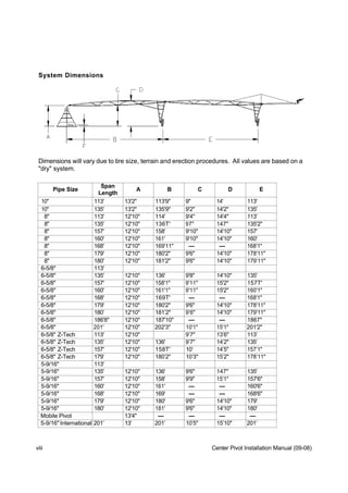
  • 1. System Dimensions Dimensions will vary due to tire size, terrain and erection procedures. All values are based on a quot;dryquot; system. Span Pipe Size A B C D E Length 10quot; 113' 13'2quot; 113'9quot; 9quot; 14' 113' 10quot; 135' 13'2quot; 135'9quot; 9'2quot; 14'2quot; 135' 8quot; 113' 12'10quot; 114' 9'4quot; 14'4quot; 113' 8quot; 135' 12'10quot; 136T' 97quot; 147quot; 135'2quot; 8quot; 157' 12'10quot; 158' 9'10quot; 14'10quot; 157' 8quot; 160' 12'10quot; 161' 9'10quot; 14'10quot; 160' 8quot; 168' 12'10quot; 169'11quot; — — 168'1quot; 8quot; 179' 12'10quot; 180'2quot; 9'6quot; 14'10quot; 178'11quot; 8quot; 180' 12'10quot; 181'2quot; 9'6quot; 14'10quot; 179’11quot; 6-5/8quot; 113' 6-5/8quot; 135' 12'10quot; 136' 9'8quot; 14'10quot; 135' 6-5/8quot; 157' 12'10quot; 158'1quot; 9'11quot; 15'2quot; 157T' 6-5/8quot; 160' 12'10quot; 161'1quot; 9'11quot; 15'2quot; 160'1quot; 6-5/8quot; 168' 12'10quot; 169T' — — 168'1quot; 6-5/8quot; 179' 12'10quot; 180'2quot; 9'6quot; 14'10quot; 178'11quot; 6-5/8quot; 180’ 12'10quot; 181’2quot; 9’6quot; 14'10quot; 179'11quot; 6-5/8quot; 186'8quot; 12'10quot; 187'10quot; — — 1867quot; 6-5/8quot; 201' 12'10quot; 202'3quot; 10'1quot; 15'1quot; 201'2quot; 6-5/8quot; Z-Tech 113' 12'10quot; 9’7quot; 13’6quot; 113’ 6-5/8quot; Z-Tech 135' 12'10quot; 136' 9’7quot; 14’2quot; 135’ 6-5/8quot; Z-Tech 157' 12'10quot; 158T' 10’ 14’5quot; 157’1quot; 6-5/8quot; Z-Tech 179’ 12'10quot; 180’2quot; 10’3quot; 15’2quot; 178’11quot; 5-9/16quot; 113' 5-9/16quot; 135' 12'10quot; 136' 9'6quot; 147quot; 135' 5-9/16quot; 157' 12'10quot; 158' 9'9quot; 15'1quot; 157'6quot; 5-9/16quot; 160' 12'10quot; 161' — — 160'6quot; 5-9/16quot; 168' 12'10quot; 169' — — 168'6quot; 5-9/16quot; 179' 12'10quot; 180' 9'6quot; 14'10quot; 179' 5-9/16quot; 180' 12'10quot; 181' 9'6quot; 14'10quot; 180' Mobile Pivot 13'4quot; — — — — 5-9/16quot; International 201’ 13’ 201’ 10’5quot; 15’10quot; 201’ viii Center Pivot Installation Manual (09-08)
  • 2. System Dimensions, Metric Dimensions will vary due to tire size, terrain and erection procedures. All values are based on a quot;dryquot; system. Span Span Pipe Size A (m) B (m) C (m) D (m) E (m) Length Length (m) 10quot; 113' 34.44 4.01 34.67 0.23 4.27 34.44 10quot; 135' 41.15 4.01 41.38 2.79 4.32 41.15 8quot; 113' 34.44 3.91 34.75 2.84 4.37 34.44 8quot; 135' 41.15 3.91 41.48 2.92 4.45 41.20 8quot; 157' 47.85 3.91 48.16 3.00 4.52 47.85 8quot; 160' 48.77 3.91 49.07 3.00 4.52 48.77 8quot; 168' 51.21 3.91 51.79 --- --- 51.23 8quot; 179' 54.56 3.91 54.91 2.90 4.52 54.53 8quot; 186' 8quot; 56.90 3.91 57.25 --- --- 56.87 6-5/8quot; 113' 34.44 6-5/8quot; 135' 41.15 3.91 41.45 2.95 4.52 41.15 6-5/8quot; 157' 47.85 3.91 48.18 3.02 4.62 47.88 6-5/8quot; 160' 48.77 3.91 49.10 3.02 4.62 48.79 6-5/8quot; 168' 51.21 3.91 51.54 --- --- 51.23 6-5/8quot; 179' 54.56 3.91 54.91 2.90 4.52 54.53 6-5/8quot; 186'8quot; 56.90 3.91 57.25 --- --- 56.87 6-5/8quot; 201' 61.26 3.91 61.34 3.07 4.60 61.01 5-9/16quot; 113' 34.44 5-9/16quot; 135' 41.15 3.91 41.45 2.90 4.45 41.15 5-9/16quot; 157' 47.85 3.91 48.16 2.97 4.60 48.01 5-9/16quot; 160' 48.77 3.91 49.07 --- --- 48.92 5-9/16quot; 179' 54.56 3.91 54.86 2.90 4.52 54.56 Mobile Pivot 4.06 --- --- --- --- Center Pivot Installation Manual (01-08) ix
  • 3. Center Points E D C B - Elbow C - Pad D - Bolt E - Bolt Type Size A - Height to Pad Outside Edge Separation Diagonal Compact 6-5/8quot; 12’10quot; 12quot; 9’ 4-1/2quot; 7’ 1/2quot; 9’ 11-1/2quot; Compact 5-9/16quot; 12’10quot; 12quot; 9’ 4-1/2quot; 9’ 11-1/2quot; 7’ 1/2quot; Standard 5-9/16quot; 12’10quot; 12quot; 12’6quot; 10’1-3/4quot; 14’4-1/4quot; Standard 6-5/8quot; 12’10quot; 12quot; 12’6quot; 10’1-3/4quot; 14’4-1/4quot; Heavy-Duty 5-9/16quot; 12’10quot; 12quot; 14’ 10’1-3/4quot; 14’4-1/4quot; Heavy-Duty 6-5/8quot; 12’10quot; 12quot; 14’ 10’1-3/4quot; 14’4-1/4quot; Heavy-Duty 8quot; 12’10quot; 12quot; 14’ 10’1-3/4quot; 14’4-1/4quot; Heavy-Duty 10quot; 12’10quot; 13 1/4quot; 14’ 10’1-3/4quot; 14’4-1/4quot; Mid-Size 5-9/16quot; 15’10quot; 12quot; 17’ 12’10 3/4quot; 18’3quot; Mid-Size 6-5/8quot; 15’10quot; 12quot; 17’ 12’10 3/4quot; 18’3quot; Mid-Size 8quot; 15’10quot; 12quot; 17’ 12’10 3/4quot; 18’3quot; Tall 5-9/16quot; 23’ 6quot; 12quot; 21’ 17’2quot; 24’ 2-1/2quot; Tall 6-5/8quot; 23’ 6quot; 12quot; 21’ 17’2quot; 24’ 2-1/2quot; Tall 8quot; 23’ 6quot; 12quot; 21’ 17’2quot; 24’ 2-1/2quot; 3 Wheel Mobile 5-9/16quot; 13’ 4quot; 39quot; --- --- --- 3 Wheel Mobile 6-5/8quot; 13’ 4quot; 39quot; --- --- --- 3 Wheel Mobile 8quot; 13’ 4quot; 39quot; --- --- --- 4 Wheel Mobile 5-9/16quot; 14’ 6quot; 2’ 8quot; --- --- --- 4 Wheel Mobile 6-5/8quot; 14’ 6quot; 2’ 8quot; --- --- --- 4 Wheel Mobile 8quot; 14’ 6quot; 2’ 8quot; --- --- --- 2 Wheel Agri-Tow 6-5/8quot; 12’10quot; --- --- --- --- *Distance from ground to ringlock ring on riser x Center Pivot Installation Manual (09-08)
  • 4. Overhang Lengths Dimensions will vary due to tire size, terrain and erection procedures. All values are based on a quot;dryquot; system. Overhang Length A B C D 11' 14' 17'6quot; 11'5quot; 22' 25' 17'6quot; 11'5quot; 33' 36' 17'6quot; 11'5quot; 44' 47' 17'6quot; 11'5quot; 55' 58' 22' 11'4quot; 66' 69' 22' 11'4quot; 88' 91' 22' 11'4quot; ST85E End Gun 2'0quot; P100 End Gun 2'4quot; P100 w/Booster Pump 3'0quot; Overhang Length on a A B C D Z-Tech Span 11' 14' 17'6quot; 12'4quot; 22' 25' 17'6quot; 127quot; 33' 36' 17'6quot; 12'11quot; 44' 47' 17'6quot; 13'5quot; 55' 58' 22' 13’9quot; 66' 69' 22' 13’ 88' 91' 22' 14’5quot; ST85E End Gun 2'0quot; P100 End Gun 2'4quot; P100 w/Booster Pump 3'0quot; Overhang Lengths, Metric (Standard Pivot) Overhang Length A B C D 11' 4.27 5.33 3.48 22' 7.62 5.33 3.48 33' 10.97 5.33 3.48 44' 14.33 5.33 3.48 55' 17.68 6.71 66' 21.03 6.71 88' 27.74 6.71 ST85E End Gun 0.61 P100 End Gun 0.71 P100 w/Booster Pump 0.91 Center Pivot Installation Manual (09-08) xi
  • 5. Span Weights Span Span Span Weight Shipping Weight Size Length/Ft Dry Wet 10quot; 113 3,909 7,593 To estimate the shipping weight of a 10quot; 135 4,129 8,529 machine, add 25 lbs. to each span 8quot; 113 3,474 5,789 selected for shipping containers and dunnage. This will give the total span 8quot; 135 3,741 6,506 weight for a machine with 11.2 tires. For 8quot; 157 4,211 7,426 a 44’ overhang, add 660 lbs. The actual 8quot; 160 4,275 7,551 shipping weight will vary due to options 8quot; 168 4,303 7,645 ordered. See examples below. 8quot; 179 4,442 8,109 8quot; 180 4,559 8,130 6 5/8quot; 135 3,545 5,419 6 5/8quot; 157 3,914 6,089 6 5/8quot; 160 3,951 6,167 6 5/8quot; 168 4,097 6,424 6 5/8quot; 179 4,477 6,959 6 5/8quot; 180 4,502 6,973 6 5/8” 186’8” 4,594 7,145 6 5/8quot; 201 4,747 7,530 6 5/8quot; Z-Tech 135 3,300 5,178 6 5/8quot; Z-Tech 157 3,618 5,797 6 5/8quot; Z-Tech 179 4,117 6,603 5 9/16quot; 135 3,145 4,459 5 9/16quot; 157 3,453 4,979 5 9/16quot; 160 3,494 5,050 5 9/16quot; 168 3,602 5,128 5 9/16quot; 179 3,751 5,489 5 9/16quot; 180 3,772 5,499 Examples: (Gen II Galvanized) 7 towers of which 3 towers are 179’ w/6-5/8quot; and 4 towers are 179’w/5-9/16quot; = Approx. 30,000 lbs. 10 towers of which 5 towers are 135’ w/6-5/8quot; and 5 towers are 135’ w/5-9/16quot; = Approx. 34,000 lbs. 18 towers of which 12 towers are 135’ w/8quot;, 3 towers are 135’ w/6-5/8quot; and 3 towers are 135’ w/5-9/16quot; = Approx. 57,000 lbs. xii Center Pivot Installation Manual (11-08)
  • 6. Component Weights (10 lbs/4.536 KG and Over) Part Number Description LB. KG. 03-0030-1 Head Weldment, Pivot 137.0 62.1 03-0070-7 Riser Weldment, Pivot 75.0 34.0 03-0106-9 Tie, Tower, 5th, Hi-Clearance, 41 1/2” 13.7 6.2 03-0110-1 Mount Weldment, Gearbox, Left 32.8 14.9 03-0120-0 Mount Weldment, Gearbox, Right 32.8 14.9 03-0129-1 Pipe, Polyethylene, 2-1/2 I.D. x 29’ 18.2 8.3 03-0337-0 Rod, Truss, Headed, 11/16” 28.0 12.7 03-0513-6 Tie, Tower, Stabilizer Attachment, 36-3/4” 11.9 5.4 03-0680-3 Joint, Pivot End, 8” w/Outlet 46.9 21.3 03-0682-9 Joint, Pivot End, 8”, Swivel, w/Outlet 26.8 12.2 03-0683-7 Joint, Tower End, 8”, w/Anchor 53.6 24.3 03-0685-2 Joint, Tower End, 8” x 6-5/8”, w/Anchor 48.9 22.2 03-0690-2 Joint, Pivot End, 6-5/8”, Swivel, w/Outlet 22.9 10.4 03-0692-8 Joint, Tower End, 6-5/8”, w/Anchor 47.8 21.7 03-0695-1 Joint, Tower End, 6-5/8” x 5-9/16”, w/Anchor 39.4 17.9 03-0699-3 Joint, Pivot End, 5-9/16”, w/Outlet 34.8 15.8 03-0702-5 Joint, Pivot End, 5-9/16”, Swivel, w/Outlet 17.2 7.8 03-0703-3 Joint, Tower End, 5-9/16”, w/Anchor 36.8 16.7 03-0706-6 Joint, Last Tower, w/Anchor 43.9 19.9 03-0728-0 Angle, Stabilizer, Second, 18’ 68.0 30.8 03-0758-7 Frame, Drive Tube, Solid Mount 185.0 83.9 03-0759-5 Frame, Drive Tube, Swivel Mount 162.0 73.5 03-0810-6 Tie, Pivot, 2nd From Bottom 14.7 6.7 03-0892-4 Angle, Mast, 66’/88’ Overhang, w/Anchor Joint 52.0 23.6 03-0893-2 Leg, Overhang, w/Anchor Joint, 84” 17.4 7.9 03-0920-3 Elbow Weld, Pivot, 6-5/8” 147.0 66.7 03-0954-2 Joint, Tower End, 10” 64.5 29.3 03-0962-5 Joint, Pivot End, Solid, 10” w/Outlet 52.5 23.8 03-0964-1 Joint, Tower End, 10” x 8”, Reduction 61.0 27.7 03-0979-9 Head Weldment, Pivot, 10” 132.0 59.9 03-0986-4 Riser Weldment, Pivot, 10” 95.0 43.1 03-1110-0 Brace, Truss Side, 51-1/2” 10.8 4.9 03-1280-1 Frame, Drive Tube, Low Profile 132.0 59.9 03-1282-7 Frame, Drive Tube, Hi-Clearance 270.0 122.5 03-2431-9 Leg, Pivot, 11’ 75.0 34.0 03-4184-2 Motor Assembly, 3/4 HP, 43 RPM 61.8 28.0 Center Pivot Installation Manual (01-08) xiii
  • 7. Part Number Description LB. KG. 03-4206-3 Head Weldment, Mobile Pivot 89.0 40.4 03-4225-3 Tongue Weldment, Mobile Pivot 100.0 45.4 03-4240-2 Brace, Leg, Mobile Pivot, 15’ 7” 89.0 40.4 03-4529-8 Caster Assy, Right, Mobile Pivot 124.5 56.5 03-4530-6 Caster Assy, Left, Mobile Pivot 123.0 55.8 03-4531-4 Caster Assy, Front, Mobile Pivot 128.4 58.2 03-4600-7 Leg, Heavy-Duty, Pivot, 11’ 110.0 49.9 03-4606-4 Brace, Lower, Riser, 61”, Mobile Pivot 12.5 5.7 03-4810-2 Generator Assy, 9 HP, TRI, 5 KW 804.0 364.7 03-4811-0 Generator Assy, 17 HP, TR 2, 10 KW 919.0 416.9 03-4812-8 Generator Assy, 23 HP, TS 3, 10 KW 978.0 443.6 03-4813-6 Generator Assy, 27 HP, TR 3, 12 KW 1035.0 469.5 03-4814-4 Generator Assy, 27 HP, TR 3, 15 KW 433.88 196.8 03-4840-9 Wheel Assy, 11.2 x 24, Right 120.0 54.4 03-4841-7 Wheel Assy, 11.2 x 24, Left 120.0 54.4 03-4842-5 Wheel Assy, 14.9 x 24, Right 156.0 70.8 03-4843-3 Wheel Assy, 14.9 x 24, Left 156.0 70.8 03-4844-1 Wheel Assy, 11 x 24.5, Recap, Right 170.0 77.1 03-4845-8 Wheel Assy, 11 x 24.5, Recap, Left 170.0 77.1 03-4853-2 Motor Assy, 1-1/2 HP, 86 RPM 74.5 33.8 03-4899-5 Ring Assy, Collector, 11 Wire 34.3 15.6 03-4984-5 Motor Assy, 1 HP, 30 RPM 72.8 33.0 03-5388-8 Tube Weldment, Horizontal 50.1 22.7 03-5389-6 Tube Weldment, Vertical 74.8 33.9 03-6707-8 Rod, Truss, Headed, 3/4”, Gr. 60 33.1 15.0 03-6709-4 Brace, Truss, 63-1/2” 13.2 6.0 03-6710-2 Brace, Truss, 81-1/4” 11.5 5.2 03-6711-0 Brace, Truss, 97-3/4” 13.6 6.2 03-6712-8 Brace, Truss, 101-3/4” 13.7 6.2 03-6714-4 Tie, Truss, 95-1/2” 10.3 4.7 03-6715-1 Tie, Truss, 123-1/2” 16.7 7.6 03-6716-9 Tie, Truss, 129-1/2” 13.7 6.2 03-6741-7 Leg, Tower, 11’ 65.3 29.6 03-6743-3 Angle, Stabilizer, 19’ 4-1/2” 75.0 34.0 03-6793-8 Coupler, 5-9/16”, Swivel Mount 29.4 13.3 03-6811-8 Coupler Weldment, 8”, Swivel Mount 56.8 25.8 03-6828-2 Elbow Weldment, Pivot, 5-9/16” 138.0 62.6 03-6837-3 Elbow Weldment, Pivot 8” 148.0 67.1 xiv Center Pivot Installation Manual (01-08)
  • 8. Part Number Description LB. KG. 03-6841-5 Leg, Tower, Low Profile, 83-1/4” 41.6 18.9 03-6917-3 Cable Electrical, 4#10, 6#14, 118.5’ 46.0 20.9 03-6918-1 Cable, Electrical, 4#10, 6#14, 140.5’ 53.8 24.4 03-6919-9 Cable, Electrical, 4#10, 6#14, 162.5’ 62.5 28.4 03-6920-7 Cable, Electrical, 4#10, 6#14, 184.5’ 70.7 32.1 03-6923-1 Cable, Electrical, 4#10, 6#14, 171’ 66.0 29.9 03-6924-9 Cable, Electrical, 4#10, 6#14, 193’ 73.3 33.2 03-6926-4 Cable, Electrical, 4#10, 6#14, 206.5’ 80.0 36.3 03-6927-2 Cable, Electrical, 4#12, 6#14, 118.5’ 38.5 17.5 03-6928-0 Cable, Electrical, 4#12, 6#14, 140.5’ 43.0 19.5 03-6929-8 Cable, Electrical, 4#12, 6#14, 162.5’ 50.0 22.7 03-6930-6 Cable, Electrical, 4#12, 6#14, 184.5’ 55.9 25.4 03-6933-0 Cable, Electrical, 4#12, 6#14, 171’ 52.0 23.6 03-6934-8 Cable, Electrical, 4#12, 6#14, 193’ 57.2 25.9 03-6936-3 Cable, Electrical, 4#12, 6#14, 206.5’ 62.0 28.1 03-6939-7 Tie, Pivot, Bottom, 92” 19.4 8.8 03-7162-5 Riser Weldment, Mobile Pivot 112.0 50.8 03-7164-1 Leg Weldment, Mobile Pivot 120.2 54.5 03-7293-8 Leg, Tower, Hi-Clearance, 15’ 7” 155.0 70.3 03-7959-4 Skid Weldment, Towable Pivot 60.0 27.2 03-7989-1 Ring Assy, Collector, 10 Wire 31.7 14.4 03-7990-9 Ring Assy, Collector, 10W, Mobile Pivot 34.3 15.6 03-8135-0 Cable, Electrical, 4#14, 6#18, 206.5 41.3 18.7 03-8137-6 Cable, Electrical, 4#14, 6#18, 193’ 38.6 17.5 03-8138-4 Cable, Electrical, 4#14, 6#18, 171’ 34.2 15.5 03-8141-8 Cable, Electrical, 4#14, 6#18, 184.5’ 38.7 17.6 03-8142-6 Cable, Electrical, 4#14, 6#18, 162.5’ 32.5 14.7 03-8143-4 Cable, Electrical, 4#14, 6#18, 140.5’ 28.1 12.7 03-8144-2 Cable, Electrical, 4#14, 6#18, 118.5’ 27.7 12.6 03-8164-0 Cable, Electrical, 4#14, 6#18, 206.5’, NS 31.0 14.1 03-8170-7 Cable, Electrical, 4#14, 6#18, 184.5’, NS 27.7 12.6 03-8171-5 Cable, Electrical, 4#14, 6#18, 162.5’ 24.4 11.1 03-8172-3 Cable, Electrical, 4#14, 6#18, 140.5’ 21.1 9.6 03-8173-1 Cable, Electrical, 4#14, 6#18, 118.5’ 17.8 8.1 03-8198-8 Pipe, Overhang, 4” x 22’, 90” Outlets 110.0 49.9 03-8209-3 Cable, Overhang, w/Pin, 82’ 5-1/2” 23.6 10.7 03-8210-1 Cable, Overhang, 1st Outboard, 43’ 14.2 6.4 03-8212-7 Cable, Overhang, 3rd Outboard, 85’ 3/4” 11.4 5.2 Center Pivot Installation Manual (01-08) xv
  • 9. Part Number Description LB. KG. 03-8215-0 15.0 6.8 Cable, 66’/88’, w/Pin 03-8242-4 Pipe Weld, 36” x 6-5/8”, Span Ext. 34.4 15.6 03-8245-7 Pipe Weld, 36” x 5-9/16”, Span Ext. 23.0 10.4 03-8247-3 Pipe Weld, 36” x 8”, Span Ext. 42.0 19.1 04-0063-0 Strap, Pivot Riser 10.9 4.9 04-0691-8 Coupler, 6-5/8”, Swivel Mount 36.3 16.5 04-0716-3 Shaft, Drive, 7/8”, 59-1/4” 12.9 5.9 04-4227-7 Plate Weld, Front Caster 23.9 10.8 04-4466-1 Plate Weld, Rear Caster 25.1 11.4 04-4830-8 Extension, Frame 13.5 6.1 04-5205-2 Rod, Safety, Trip, 10’ Long 15.1 6.8 04-5206-0 Bracket, Safety, Trip, 52” Long 15.0 6.8 04-6029-5 Ring, 5-9/16” Alignment 12.5 5.7 04-6758-9 Ring, 6-5/8” Alignment 22.9 10.4 04-6814-0 Ring Weld, Octagon, 8” 35.7 16.2 04-7165-6 Bracket, Main Panel 16.9 7.7 06-2506-1 Pump, Booster, 130 GPM 63.6 28.8 06-3502-9 Pump, Booster, 200 GPM 133.3 60.5 06-4281-9 Pipe, Polyethylene, 2-1/2 I.D. x 40’ 25.2 11.4 10-0052-0 Panel, Control, Auto-Rev/Stop 10.3 4.7 10-0678-2 Pipe, Overhang, 5-9/16” x 11’ 75.0 34.0 10-4566-5 Hitch Weld, Towing 37.7 17.1 10-4571-5 Tongue Weld, Agri-Tow 24.4 11.1 10-5029-3 Sign, Zimmatic 19.2 8.7 10-5582-1 Brace, Diagonal, Tower, 52-3/8” 11.6 5.3 10-9008-3 Joint, End, Safety Rod Mount 11.8 5.4 10-9186-7 Pipe, Safety, 5-9/16” x 22’ 145.0 65.8 10-9194-1 Shield, Collector Ring, 10” 22.1 10.0 10-9195-8 Weld, Collector Ring, Support 11.2 5.1 10-9438-2 Hose, Flex, 3/4” I.D. 36.0 16.3 10-9689-0 Frame, Cover, Engine, Front 11.6 5.3 10-9690-8 Cover, Engine, Front 31.0 14.1 10-9693-2 Frame Weld, Rear, Generator Cover 18.9 8.6 10-9695-7 Cover, Generator, Rear 14.3 6.5 10-9745-0 Brace, Angle, Mobile Pivot, 70-1/4” 23.0 10.4 10-9808-6 Mount Weldment, 10” Collector Ring 12.0 5.4 10-9813-6 Angle, Stabilizer, Hi-Clearance, 20’ 8-1/4” 132.0 59.9 10-9814-4 Tie, Truss, 51-1/2” 15.4 7.0 xvi Center Pivot Installation Manual (01-08)
  • 10. Part Number Description LB. KG. 10-9815-1 Brace, Truss, 77-1/2”, R.H. 20.9 9.5 10-9816-9 Brace, Truss, 74-1/4”, L.H. 19.9 9.0 10-9817-7 Brace, Diagonal, Hi-Clearance, 57” 15.1 6.8 11-0037-9 Pipe Weldment, 12” x 6-5/8” Span Ext. 16.7 7.6 11-0062-7 Joint, Pivot End, 6-5/8”, w/Outlet 44.3 20.1 11-0169-0 Beam, Weldment, 4 Wheel Mobile Pivot 165.0 74.8 11-0170-8 Angle, Tie, 112”, 4 Wheel Mobile Pivot 70.0 31.8 11-0171-6 Angle, Tongue, 120”, 4 Wheel Mobile Pivot 62.0 28.1 11-0174-0 Tongue Weldment, 4 Wheel Mobile Pivot 13.0 5.9 11-0176-5 Angle, Crosstie, Tongue, 60” 31.0 14.1 11-0312-6 Assembly, 8”, Encoder Drive 13.1 5.9 11-0345-6 Assembly, 10”, Encoder Drive 16.2 7.3 11-0460-3 Cable Assy, 4 Wheel Mobile Pivot, 22’ 22.7 10.3 11-0814-1 Tube Weldment, Torque, 119-3/4” 77.0 34.9 11-0843-0 Winch Plate Weldment 14.7 6.7 11-0902-4 Anchor Weldment, Pivot, 10” 16.4 7.4 11-0984-2 Spindle Assembly, 4 WMP 52.1 23.6 11-0993-3 Wheel Assy, 16” x 8 Bolt, Recap 60.0 27.2 11-1226-7 Valve, 2” Aqua, 425 Nozzle 13.4 6.1 11-1736-5 Gearbox, Towable, Heavy-Duty 119.8 54.3 11-1789-4 Bar, Alignment, Non-Wire 14.9 6.8 11-2249-8 Riser, Internal, 10” 10.9 4.9 11-2250-6 Elbow Weld, 10”, Pivot 178.0 80.7 11-2251-4 Riser Weld, 10” 103.0 46.7 11-3326-3 Guard Weld, Crop, Rev-Tow 16.1 7.3 11-3648-0 Pipe, Half, 6-5/8”, 90” Outlets 205.0 93.0 11-3649-8 Pipe, Span, 6-5/8”, 90” Outlets 410.0 186.0 11-3650-6 Pipe, Half, 5-9/16”, 90” Outlets 150.0 68.0 11-3651-4 Pipe, Span, 5-9/16”, 90” Outlets 300.0 136.1 11-3654-8 Pipe Half, 8”, 90” Outlets 240.0 108.9 11-3655-5 Pipe, Span, 8”, 90” Outlets 480.0 217.7 11-3656-3 Pipe, Half, 10”, 90” Outlets 300.0 136.1 11-3657-1 Pipe, Span, 10”, 90” Outlets 595.0 269.9 11-3658-9 Pipe, 6-5/8” x 11’ Extension 125.0 56.7 11-3659-7 Pipe, 6-5/8” x 7’ 8” Extension 82.7 37.5 11-3816-3 Leg, Super-Hi Tower, 18’ 10-3/8” 188.0 85.3 11-3823-9 Tie, Tower, 5th, 36-7/8” 19.3 8.8 11-3826-2 Tie, Tower, 8th, 49-1/2” 10.2 4.6 Center Pivot Installation Manual (01-08) xvii
  • 11. Part Number Description LB. KG. 11-3827-0 Stabilizer, Tower, 138-1/16” 75.0 34.0 11-3828-8 Stabilizer, R., Reinforce, 68-13/16” 14.4 6.5 11-3829-6 Stabilizer, L., Reinforce, 66-1/16” 13.8 6.3 11-3830-4 Stabilizer, Right, 243-7/8” 126.0 57.2 11-3831-2 Stabilizer, Left, 243-7/8” 126.0 57.2 11-3839-5 Frame, Drive Tube, Super Hi-Clearance 305.0 138.3 11-3941-9 Shaft, Drive, 7/8”, 86-3/4” 18.8 8.5 11-3943-5 Shaft, Drive, 7/8”, 102-5/8” 22.4 10.2 11-4054-0 Stabilizer, Plate, Lower, Super Hi-Clearance 11.2 5.1 11-4055-7 Stabilizer, Plate, Upper, Super Hi-Clearance 27.8 12.6 11-4317-1 End Gun, Komet, 101 SL. RV, 18 Deg. 19.5 8.8 11-5491-3 Wheel Assy, 11 x 22.5 Recap, Right 175.0 79.4 11-5492-1 Wheel Assy, 11 x 22.5 Recap, Left 175.0 79.4 11-6133-0 Elbow, Pivot, 6-5/8”, Stainless Steel 124.0 56.2 11-6152-0 Elbow, 8” x 90 Deg., Stainless Steel 17.0 7.7 11-6157-9 Riser Weld, Pivot, Stainless Steel 72.0 33.0 11-7827-6 Panel, FieldBOSS, 480 Volt 105.0 47.6 11-7829-2 Panel, FieldBOSS, 380 Volt, CE 105.0 47.6 11-8391-0 Panel, FieldBASIC, 480 Volt 105.0 47.6 11-8393-0 Panel, FieldBASIC, 380 Volt, CE 105.0 47.6 11-8409-0 Gearbox, PowerDrive, Non-Tow 130.0 59.00 13-3057-0 Pipe, Half, 6-5/8”, 90” Outlets, .096 185.0 83.9 13-3058-0 Pipe, Span, 6-5/8”, 90” Outlets, .096 346.0 156.9 13-3059-0 Pipe, Half, 6-5/8”, 30” Outlets, .096 185.0 83.9 13-3060-0 Pipe, Span, 6-5/8”, 30” Outlets, .096 346.0 156.9 13-5725-0 Head Weldment, Pivot 129.3 58.7 14-1714-0 Track, Assembly, Turf 550 248.8 14-1715-0 Track, Assembly, Ag 10-Bar 550 248.8 66-2249-2 Elbow, Steel, 8” x 90 Deg. 16.9 7.7 88-4648-7 End Gun, Nelson, P150R 40.4 18.3 88-5265-9 End Gun, Nelson, SR100 27.6 12.5 88-5280-8 End Gun, Nelson, SRNV100 32.1 14.6 xviii Center Pivot Installation Manual (01-08)
  • 12. Structural Component Specifications Pivot (4 Leg) Optional Legs 4quot; x 4quot; x 1/4quot; 4quot; x 4quot; x 3/8quot; Ties 2quot; x 2quot; x 3/16quot; Riser 8quot; O.D. Tubing Elbow 8quot; O.D. Cast 10quot; Pivot (4 Leg) Legs 4quot; x 4quot; x 3/8quot; Ties 2quot; x 2quot; x 3/16quot; Riser 10quot; O.D. Tubing Elbow 10quot; O.D. Cast Towers Drive Tube 6-5/8quot; x 11 Ga. Tubing 13.0 Ft. Wheel Base Standard 8.6 Ft. Wheel Base Low Profile 17.7 Ft. Wheel Base High Profile Tower Legs 3quot; x 4quot; x 1/4quot; 4quot; x 4quot; x 3/8quot; Hi-Clearance Heavy-Duty Braces 1-1/2quot; x 1-1/2quot; x 1/8quot; (Standard Tower) 2quot; x 2quot; x 3/16quot; (Medium and High Clearance Tower) Spans Pipe 10quot; 10quot; O.D. x 11 Ga. (.107 Min.) 8quot; 8quot; O.D. x 11 Ga. (.107 Min.) 6-5/8quot; 6-5/8quot; O.D. x 11 Ga. 5-9/16quot; 5-9/16quot; O.D. x 12 Ga. (.097 Min.) 5-9/16quot; O.D. x 4 MM (International Only) 5-9/16quot; O.D. x 11 Ga. (International Only) Truss Braces 10quot;, 8quot;, 6-5/8quot;, 5-9/16quot; 2quot; x 2quot; x 3/16quot; Braces 2quot; x 2quot; x 1/8quot; Braces 1-1/2quot; x 1-1/2quot; x 1/8quot; Ties 2quot; x 2quot; x 1/8quot; 3rd Tie Truss Rods 10quot; - 135’ 3/4quot; Diameter, A572-Gr. 60 8quot; - 168’-179’ 3/4quot; Diameter, A572-Gr. 60 6-5/8quot; - 201’ 3/4quot; Diameter, A572-Gr. 60 10quot; - 113’ 11/16quot; Diameter, A572-Gr. 60 11/16quot; Diameter, A572-Gr. 60 8quot; - 113’, 135’, 157’ 11/16quot; Diameter, A572-Gr. 60 6-5/8quot; - 113’, 135’, 157’, 179’ 5-9/16quot;-113’, 135’, 157’, 179’, 201’ 11/16quot; Diameter, A572-Gr. 60 Center Pivot Installation Manual (09-08) xix
  • 13. Z-Tech Structural Component Specifications Compact Pivot Point Legs 4quot; x 4quot; x 1/4quot; Ties 2quot; x 2quot; x 1/8quot; Riser 8quot; O.D. Tubing Elbow 8quot; O.D. Cast Z-Tech Spans Pipe 6-5/8quot; 6-5/8quot; O.D. x 12 Ga. (.097 Min.) Truss Braces 2quot; x 2quot; x 1/8quot; Braces Truss Ties 1-1/2quot; x 1-1/2quot; x 1/8quot; Truss Rods 11/16quot;, Grade 60 Recommended Torque Values for Cap Screws Grade 2 Grade 5 Grade 8 1/4” Coarse 5 ft. lbs. 8 ft. lbs. 12 ft. lbs. Fine 6 ft. lbs. 10 ft. lbs. 14 ft. lbs. 5/16” Coarse 11 ft. lbs. 17 ft. lbs. 24 ft. lbs. Fine 13 ft. lbs. 19 ft. lbs. 27 ft. lbs. 3/8” Coarse 18 ft. lbs. 31 ft. lbs. 44 ft. lbs. Fine 20 ft. lbs. 35 ft. lbs. 49 ft. lbs. 7/16” Coarse 28 ft. lbs. 49 ft. lbs. 70 ft. lbs. Fine 30 ft. lbs. 55 ft. lbs. 78 ft. lbs. 1/2” Coarse 39 ft. lbs. 75 ft. lbs. 105 ft. lbs. Fine 41 ft. lbs. 85 ft. lbs. 120 ft. lbs. 9/16” Coarse 51 ft. lbs. 110 ft. lbs. 155 ft. lbs. Fine 55 ft. lbs. 120 ft. lbs. 170 ft. lbs. 5/8” Coarse 83 ft. lbs. 150 ft. lbs. 210 ft. lbs. Fine 95 ft. lbs. 170 ft. lbs. 240 ft. lbs. 3/4” Coarse 105 ft. lbs. 270 ft. lbs. 375 ft. lbs. Fine 115 ft. lbs. 295 ft. lbs. 420 ft. lbs. 7/8” Coarse 160 ft. lbs. 395 ft. lbs. 605 ft. lbs. Fine 175 ft. lbs. 435 ft. lbs. 675 ft. lbs. 1” Coarse 235 ft. lbs. 590 ft. lbs. 910 ft. lbs. Fine 250 ft. lbs. 660 ft. lbs. 980 ft. lbs. xx Center Pivot Installation Manual (09-08)
  • 14. Section 1 - 4-Leg Pivot Alternate Concrete Pad for Towable Systems NOTE^ Local soil conditions must be considered before selecting pad. Pad with lf reduced concrete should not be used on light soils. Maximum System Length for this Pad is 1350’ to Last Wheel Track. 12 12' 6 PART NO. 3 - 1 2 7 0 - 2 ANCHOR CHAIN 12quot; OF CHAIN ON 10' 10quot;±2quot; TOP OF CONCRETE. 10' 10 ± 2 12' 6quot; CENTER THE REINFORCEMENT ASSEMBLY INTO THE FOOTING. POSITION 2quot; DOWN FROM SURFACE. I 6quot; WIDE, 15quot; DEEP FOOTING BETWEEN CORNERS. 4 ' ' ..!; ' !' ;quot;]i '•0,1 SECTION 3-B 16 DIA. TYP r 15 3 SECTION A - A Figure 1.7 Center Pivot Installation Manual (06-06) 1-9
  • 15. Section 1 - 4-Leg Pivot Heavy Duty Non-Tow Pivot Assembly, 8”, 6-5/8”, 5-9/16” Heavy Duty Non-Tow Pivot Assembly, 8”, Stainless Steel NOTE: COAT THE PIVOT ELL WITH ON 8” STAINLESS STEEL PIVOTS, GREASE BEFORE INSTALLING THE USE 11-6157-9, RISER WELDMENT, PIVOT ELL INTO THE HEAD. AFTER PIVOT, STAINLESS STEEL, IN PLACE INSTALLING THE PIVOT ELL INTO THE PIVOT HEAD, PUMP ANOTHER O F ITEM # 2 . TUBE OF GREASE INTO THE PIVOT HEAD USING A TOTAL OF TWO TUBES OF GREASE. 16)26 A F T E R S E P T . 2003 Figure 1.14 Ref. Part No. Description Ref. Part No. Description 1 3-0030-1 Head Weldment, Pivot 16 6-2418-9 Nut, 1/2-13, Lock 2 3-0070-7 Riser Weldment, Pivot 17 11-0024-7 Nut, 7/8-9, Lock, Nylon Insert 3 3-0810-6 Tie, Pivot, 2nd From Bottom 18 11-0046-0 Decal, “Grease” 4 3-0830-4 Tie, Pivot, Top 19 11-0470-2 Zerk, 5/16”, Drive-In 5 3-1110-0 Brace, Truss Side, 51-1/2” 20 11-7827-6 Panel, FieldBOSS, 480 Volt 6 3-4600-7 Leg, Heavy Duty, Pivot 21 11-7829-2 Panel, FieldBOSS, 380 Volt, CE 7 3-4772-4 Anchor Weldment, Pivot, Non-Tow 22 11-8391-0 Panel, FieldBASIC, 480 Volt 8 3-6939-7 Tie, Pivot Bottom, 92” 23 11-8393-0 Panel, FieldBASIC, 380 Volt, CE 9 4-0063-0 Strap, Pivot Riser 24 11-9461-0 Tie, Pivot, Panel Mount, Top 10 4-4775-5 Washer, Rectangle, 15/16” x 2-1/2 x 3” 25 11-9462-0 Tie, Pivot, Panel Mount, Bottom 11 6-0804-2 Screw, 1/2-13 x 1-1/4”, Hex, Gr.5 26 26-0760-4 Screw, 1/2-13 x 1-1/2”, Hex, Gr. 5 12 6-0809-1 Screw, 3/4-10 x 2”, Hex, Gr.5 27 11-6157-9 Riser Weld., Pivot, Stainless Steel 13 6-0839-8 Screw, 5/8-11 x 1-1/2”, Hex, Gr. 5 28 13-3634-0 Panel, FieldVISION, 480V 14 6-2416-3 Nut, 5/8-11, Lock 29 13-5533-0 Panel, FieldVISION, 380V, CE 15 6-2417-1 Nut, 3/4-10, Lock 1-18 Center Pivot Installation Manual (06-06)
  • 16. Section 1 - 4-Leg Pivot Non-Tow Pivot Assembly, 6-5/8”, 5-9/16”, Compact Pivot Non-Tow Pivot Assembly, 5-9/16”, Compact Pivot, Stainless Steel Original Original Ref. Part No. Description Ref. Part No. Description 1 3-0070-7 Riser, Pivot 18 10-3475-0 Panel, Mount, Top 2 6-0649-1 Tee, Pipe, 1/4” 19 11-3531-8 Tubing, Plas., 1/4”OD x.040” Wall 3 6-0652-5 Nipple Pipe, 1/4 x 2 20 11-7827-6 Panel, FieldBOSS, 480 Volt 4 6-0804-2 Screw, 1/2-13 x 1-1/4”, Hex, Gr. 5 21 11-7829-2 Panel, FieldBOSS, 380 Volt, CE 5 6-0809-1 Screw, 3/4-10 x 2”, Hex, Gr. 5 22 11-8391-0 Panel, FieldBASIC, 480V 6 6-0816-6 Washer, Lock, 3/4” 23 11-8393-0 Panel, FieldBASIC, 380 Volt, CE 7 6-0826-5 Nut, 3/4-10, Hex 24 13-3634-0 Panel, FieldVISION, 480V 8 6-0839-8 Screw, 5/8-11 x 1-1/2”, Hex, Gr. 5 25 13-5533-0 Panel, FieldVISION, 380V, CE 9 6-0840-6 Bolt, 1/4-20 x 2-1/2, J 26 13-5727-0 Leg, Pivot, 10’ 10 6-0841-4 Nut, 1/4-20, Hex 27 13-5859-0 Brace, Truss Side, 40-1/2” 11 6-0842-2 Washer, Flat, 1/4” 28 13-5860-0 Tie, Pivot, 2nd fm Bottom, 55-1/2” 12 6-0956-0 Connector, Hose, 1/4” x 1/4” MPT 29 13-5861-0 Tie, Truss, 70” 13 6-2159-9 Connector, Hose, 1/4” x 1/8” MPT 30 13-5725-0 Head Weldment, Pivot 14 6-2416-3 Nut, 5/8-11, Lock 31 13-5862-0 Strap, Pivot Riser 15 6-2418-9 Nut, 1/2-13, Lock 32 13-6473-0 Bracket, Panel Mount, Bottom 16 6-3343-8 Gauge, Pres., Liq-Filled, 0-160 33 26-0760-4 Screw, 1/2-13 x 1-1/2”, Hex, Gr. 5 17 6-4715-6 Gauge, Pres., Liq-Filled, 0-100 34 11-6157-9 Riser, Pivot, Stainless Steel Foot Options, Compact Pivot (Pivot Foot not interchangeable with Gen II standard pivot point) 84.5” Spacing bolt 78” Spacing bolt pattern pattern Chain Tie Down Option Ref. Part No. Description Ref. Part No. Description 1 6-0839-8 Screw, 5/8-11 x 1-1/2”, Hex, Gr. 5 6 6-2382-7 Hook, Eye Grab, 1/2” 2 6-2416-3 Nut, 5/8-11, Lock 7 13-5807-0 Anchor, Pivot, Non-Tow 3 4-2776-5 Bracket, Pivot Leg 8 13-9497-0 Angle, Bottom, Pivot 4 4-4775-5 Washer, Rectangle, 15/16” x 2-1/2 x 3” 9 13-9871-0 Anchor Weldment, Pivot 5 6-0011-4 Turnbuckle, 3/4 x 6 Clev.End,w/Pin Center Pivot Installation Manual (08-07) 1-21
  • 17. Section 1 - 4-Leg Pivot Single Panel Mounting ~N SINGLE PANEL MOUNTING 1 NOTES: 1. THE TOP AND BOTTOM MOUNTING BRACKETS CAN BE USED TO MOUNT ANY 24quot; x 24quot; x 8quot;, OR 24quot; x 16quot; x 8quot; PANELS. 2. MOUNT THE TOP BRACKETS, ITEM #10, TO THE 3RD PIVOT TIE AND THE BOTTOM BRACKETS, ITEM #9, TO THE 2ND PIVOT TIE. LEAVE THE SCREWS LOOSE. 3. INSERT 2 EA. OF ITEM #4, 1/4-20 x 1quot; HEX SCREW INTO THE 2 WELD NUTS AT THE BOTTOM REAR OF THE ENCLOSURE AS SHOWN. THESE SCREWS WILL EXTEND OUT THE BOTTOM OF THE PANEL AND ALLOW THE BOTTOM BRACKET, ITEM #9, TO BOLT ON. FASTEN WITH ITEM #3, 1/4quot; LOCK WASHER AND ITEM #2, 1/4-20 NUT. 4. ATTACH THE TOP BRACKETS, ITEM #10 TO THE PANEL ENCLOSURE WITH 2 EA. ITEM #3, 1/4quot; LOCK WASHERS AND ITEM #5, 1/4-20 x 3/4quot; SCREWS. YOU CAN NOW TIGHTEN ALL FASTENERS. 5. PLUG THE 4 WELD NUTS IN THE LOWER FRONT OF THE PANEL WITH ITEM #6, 1/4-20 x 3/8quot; SCREWS. Ref. Part No. Description 1 Any 24” x 24” x 8” Panel 2 6-0841-4 Nut, 1/4-20, Hex 3 6-1510-4 Washer, Lock, 1/4” 4 6-3936-9 Screw, 1/4-20 x 1”, Hex, Gr. 5 5 10-2985-9 Screw, 1/4-20 x 3/4”, Hex, Gr. 5 6 11-3062-4 Screw, 1/4-20 x 3/8”, Hex, Type 23 7 11-9461-0 Tie, Pivot, Panel Mount, Top, 51 1/2” 8 11-9462-0 Tie, Pivot, Panel Mount, Bottom, 71 11/16” 9 11-9515-0 Bracket, Panel Mount, Lower 10 11-9516-0 Bracket, Panel Mount, Upper 1-28 Center Pivot Installation Manual (06-06)
  • 18. Section 1 - 4-Leg Pivot Main Panel Accessibility NOTE: MAINTAIN A WORKING CLEARANCE IN FRONT OF MAIN PANEL. DISTANCES ARE MEASURED FROM THE ENCLOSURE FRONT. Figure 1.21 Pressure Switch Adjustment The pressure switch is located in the lower right switch. Turn the knurled adjustment knob corner of the main control panel. To adjust clockwise to increase the pressure. When the pressure switch, pressurize the system to its pressure switch setting becomes greater than normal operating position. Then start the the pivot pressure, the pivot will shut down. Turn system with the Wet/Dry switch in Wet position. the pressure adjustment knob counter clockwise (End gun should be on if used.) Next slowly to the desired low pressure shutdown setting. increase the pressure setting of the pressure ADJUSTMENT KNOB Figure 1.22 1-30 Center Pivot Installation Manual (06-06)
  • 19. Section 1 - 4-Leg Pivot Elbow Assembly, 8”, 6-5/8”, 5-9/16” SEE REPAIR PARTS MISC. SECTION FOR ITEMS 1, 2 & 3. NOTE: COAT THE PIVOT ELL WITH GREASE BEFORE INSTALLING THE PIVOT ELL INTO THE HEAD. AFTER INSTALLING THE PIVOT ELL INTO THE PIVOT HEAD, PUMP ANOTHER TUBE OF GREASE INTO THE PIVOT HEAD USING A TOTAL OF TWO TUBES OF GREASE. Ref. Part No. Description 1 Coupler, 6-5/8”, Split 2 Coupler, 5-9/16”, Split 3 Coupler, 8”, Split 4 3-0030-1 Head Weldment, Pivot 5 4-0058-0 Bracket, Automatic Shutdown 6 3-0070-7 Riser Weldment, Pivot 7 3-0860-1 Bracket, Collector Ring Shield Holder 8 3-0920-3 Elbow Weldment, Pivot, 6-5/8” 9 3-4865-6 Band, Collector Ring 10 3-6828-2 Elbow Weldment, Pivot, 5-9/16” 11 3-6837-3 Elbow Weldment, Pivot, 8” 12 3-7989-1 Ring Assy, Collector 13 6-0120-3 Nut, 3/8-16, Hex 14 6-0200-3 Gasket, Collector Ring, Top 15 6-0210-2 Gasket, Collector Ring, Bottom 16 6-0794-5 Gasket, Deflector, 8” 17 6-0800-0 Screw, 5/16-18 x 3/8”, Hex 18 6-0804-2 Screw, 1/2-13 x 1-1/4”, Hex, Gr.5 19 6-0820-8 Washer, 1/2”, Rubber Seal 20 6-2418-9 Nut, 1/2-13, Lock 21 6-3091-3 Shield, Collector Ring 22 6-3658-9 Screw, 3/8-16 x 2-1/4”, Hex, Gr.5 23 9-0838-4 Connector, 3/4”, w/Nut 24 11-0046-0 Decal, “Grease” 25 11-0470-2 Zerk, 5/16”, Drive-In 28 *26 11-3279-4 Ring, Shutdown Clamp 27 66-0640-4 Clamp, Ringlock, 8” Steel Coupler 28 66-1070-3 Gasket, Round Back 29 66-2249-2 Elbow, Steel, 8” x 90 o 30 11-6659-4 Riser Weldment, 8” Mid-Size Figure 1.23 *NOTE: 11-3279-4 is required when pivot application requires auto-reverse or stop using kit #10-0233-6. Center Pivot Installation Manual (06-06) 1-31
  • 20. Section 1 - 4-Leg Pivot Elbow Assembly, 8”, 6-5/8”, Stainless Steel SEE REPAIR PARTS MISC. SECTION FOR ITEMS 1 & 2. NOTE: COAT THE PIVOT ELL WITH GREASE BEFORE INSTALLING THE PIVOT ELL INTO THE HEAD. AFTER INSTALLING THE PIVOT ELL INTO THE PIVOT HEAD, PUMP ANOTHER TUBE OF GREASE INTO THE PIVOT HEAD USING A TOTAL OF TWO TUBES OF GREASE. Ref. Part No. Description 1 Coupler, 6-5/8”, Split 2 Coupler, 8”, Split 3 3-0030-1 Head Weldment, Pivot 4 3-0860-1 Bracket, Collector Ring Shield Holder 5 3-4865-6 Band, Collector Ring 6 3-7989-1 Ring Assy, Collector 7 4-0058-0 Bracket, Automatic Shutdown 8 6-0120-3 Nut, 3/8-16, Hex 9 6-0200-3 Gasket, Collector Ring, Top 10 6-0210-2 Gasket, Collector Ring, Bottom 11 6-0794-5 Gasket, Deflector, 8” 12 6-0800-0 Screw, 5/16-18 x 3/8”, Hex 13 12-8163-0 Screw, 1/2-13 x 1-1/2”, Hex, S.S. 14 11-6141-3 Washer, 1/2”, Rubber Seal, S.S. 15 6-2418-9 Nut, 1/2-13, Lock 16 6-3091-3 Shield, Collector Ring 17 6-3658-9 Screw, 3/8-16 x 2-1/4”, Hex, Gr.5 18 9-0838-4 Connector, 3/4”, w/Nut 19 11-0046-0 Decal, “Grease” 20 11-0470-2 Zerk, 5/16”, Drive-In *21 11-3279-4 Ring, Shutdown Clamp 22 11-6133-0 Elbow Weldment, Pivot, 6-5/8” 23 11-6152-0 Elbow, Steel, 8” x 90 o 24 11-6157-9 Riser Weldment, Pivot, Stainless Steel 25 11-6481-3 Elbow Weldment, Pivot, 8” 26 66-0640-4 Clamp, Ringlock, 8” Steel Coupler 27 66-1070-3 Gasket, Round Back Figure 1.24 *NOTE: 11-3279-4 is required when pivot application requires auto-reverse or stop using kit #10-0233-6. 1-32 Center Pivot Installation Manual (03-08)
  • 21. Section 1 - 4-Leg Pivot Encoder Detail, Pivot, 8”, 6-5/8”, 5-9/16” (Elbow Section) NOTE: Slide the encoder mount along the pivot head gusset so the gear is parallel to the pin gear FREEDOM FOR 3/8quot; weldment making sure the panel TRAVEL BETWEEN PIN cover can be removed. AND FOLLOWER Assembly Instructions, Encoder Drive (Not applicable to Mobile Pivot) Ref. Part No. Description 1. Install the pin gear in place of the shutdown 1 3-0030-1 Head Weldment, Pivot bracket with the pins up. Tighten bolts in 2 3-0070-7 Riser Weldment, Pivot slotted holes last to insure gear is concentric to 3 6-0794-5 Gasket, Deflector pivot elbow pipe. 4 6-0804-2 Screw, 1/2-13 x 1-1/4”, Hex, Gr. 5 NOTE: If holes do not line up, use a rat tail file 5 6-0820-8 Washer, 1/2”, Rubber Seal to increase the size of the holes in the pin gear 6 6-2221-7 Screw, 3/8-16 x 1”, Hex, Gr. 5 until bolts can be installed. 7 6-2418-9 Nut, 1/2-13 2. Assemble the encoder base to the mount 8 6-4267-8 Nut, 1/4-20, Lock, Nylon Insert weldment with the shoulder bolt provided in the 9 6-4364-3 Nut, 5/16”, Lock kit. This hinged joint must pivot freely. A grease zerk has been provided. Position the 10 10-2985-9 Screw, 1/4-20 x 3/4”, Hex, Gr. 5 mount so solid gear sits parallel with the pin 11 11-0046-0 Decal, “Grease” gear and near the middle of the pin length. 12 11-0334-0 Gear, Pin, 8” 3. Install the encoder panel on a pivot head leg 13 11-0470-2 Zerk, 5/16”, Drive-In gusset as shown. The appropriate leg gusset 14 11-6015-9 Gear, 8”, 12 Gauge will usually be the one which allows encoder 15 11-6419-3 Screw, 5/8” x 3-1/2”, Socket Hd, Ptd. panel to sit 90o to the main panel and away 16 11-6659-4 Riser Weldment, 8”, Mid-Size from the grease zerks in the head pipe. 17 12-9350-0 Mount, 8” Encoder 4. Make sure the gear will separate from contact 18 13-9490-0 Encoder Assy, Magnetic, Drive, with the pin gear by about 3/8” and the cover 19 66-1070-3 Gasket, Round Back can be removed. If not, readjust. Center Pivot Installation Manual (09-08) 1-35
  • 22. Section 1 - 4-Leg Pivot Collector Ring Mounting A. Slide the collector ring band (5) over the pivot head weldment (3), then slide the collector ring and shield assemblies (6) over the pivot head weldment. B. Proceed to lubricate and install the pivot elbow (1) as detailed in the Installation Manual. C. Loosen the nuts holding the collector ring brackets (12) and slide the brackets in so that they are flush against the tubing of the pivot head weldment (3), then re-tighten the nuts to hold the brackets (12) in this position. D. Raise the collector ring assembly making certain that the slot in the top bearing engages the drive pin on the underside of the top shield on the pivot elbow. Seat the collector ring firmly up against the shield. Slide the collector ring band (5) up around the collector ring brackets (12) and the pivot head weldment (3) as shown. Using the 3/8” screw (11) and the nut (7), clamp the collector ring (6) to the pivot head weldment (3). Slide the collector ring shield down and install the span cable. Slide collector ring shield up into position (insure gaskets are properly seated) and secure to pivot elbow with Items (9, 4). Route collector ring cable down the pivot and secure to structure with clamps provided. Connect cable in main control per Detail B and main panel terminal color code. Ref. Part No. Description 1 Elbow Weldment, Pivot 2 Cable, 1st Span 3 3-0030-1 Head Weldment, Pivot 4 3-0860-1 Bracket, Collector Ring Shield Holder 5 3-4865-6 Band, Collector Ring 6 3-7989-1 Ring Assy, Collector 7 6-0120-3 Nut, 3/8-16, Hex 8 6-0200-3 Gasket, Collector Ring, Top 9 6-0800-0 Screw, 5/16-18 x 3/8”, Hex 10 6-3091-3 Shield, Collector Ring 11 6-3658-9 Screw, 3/8-16 x 2 1/4”, Hex, Gr. 5 12 6-3866-8 Bracket, Collector Ring 13 6-3868-4 Spring, Brush, Collector Ring 14 9-0838-4 Connector, 3/4”, w/Nut 15 9-7610-0 Term Wire, C, 16-14, Spade 10, INS 16 9-7614-2 Term Wire, F, 10-12, Spade, 10, INS 17 9-9163-8 Brush, Collector Ring 18 9-9311-3 Term Wire, 22-18, Spade 10, INS CONDUCTOR OF 1ST COLOR OF SPAN CABLE SPAN CABLE COLLECTOR RING COLOR CODE DET CONDUCTOR TO BE #1 GREEN #6 YELLOW TERMINATED AT THIS TERMINAL. Figure 1.28 #2 WHITE #7 BROWN #3 PURPLE #8 BLUE #4 ORANGE #9 RED TO CONNECT THE INCOMING 1ST SPAN CABLE TO THE COLLECTOR RING #5 #10 PINK BLACK TERMINALS, SEE DETAIL quot;Aquot;. EACH COLLECTOR RING BRUSH SPRING (16) IS COLOR CODED WITH COLORED TAPE TO IDENTIFY WHICH SPAN CABLE CONDUCTOR IS TO BE TERMINATED THERE. TO TERMINATE, ATTACH A TERMINAL (15, 16 & 18) TO THE CONDUCTOR USING A PHILLIPS SCREW DRIVER. LOOSEN THE TERMINAL SCREW AND POSITION THE TERMINAL (15, 16 & 18) ATTACHED TO THE CONDUCTOR AS SHOWN AND TIGHTEN THE TERMINAL SCREW. MAIN CONTROL TB2 MAIN PANEL TERMINAL COLOR CODE PANEL #1 - PINK #5 - PURPLE #2 - YELLOW #9 - BROWN #3 - ORANGE #10 - GREEN #4 - WHITE TB4 MAIN PANEL TERMINAL COLOR CODE #6 - BLACK #7 - RED SEE COLOR CODE LIST #8 - BLUE DETAIL quot; B quot; Center Pivot Installation Manual (06-06) 1-37
  • 23. Section 1 - 4-Leg Pivot 10” Riser Assembly 11 120) #1 - GREEN #6 - YELLOW #2 - WHITE #7 - BROWN #3 - PURPLE #8 - BLUE COLOR OF SPAN CABLE CONDUCTOR OF #4 - ORANGE #9 - RED CONDUCTOR TO BE TERMINATED FIRST SPAN CABLE #5 - PINK #10 - BLACK AT THIS TERMINAL DETAIL quot;Aquot; TO CONNECT THE INCOMING 1ST SPAN CABLE TO THE COLLECTOR RING TERMINALS, SEE DETAIL quot;Aquot;. EACH COLLECTOR RING BRUSH SPRING (16) IS COLOR CODED WITH COLORED TAPE TO IDENTIFY WHICH SPAN CABLE CONDUCTOR IS TO BE TERMINATED THERE. TO TERMINATE, ATTACH A TERMINAL (21, 22 & 25) TO THE CONDUCTOR USING A PHILLIPS SCREW DRIVER. LOOSEN THE TERMINAL SCREW AND POSITION THE TERMINAL (21, 22 & 25) ATTACHED TO THE CONDUCTOR AS SHOWN AND TIGHTEN THE TERMINAL SCREW. TB2 MAIN PANEL TERMINAL COLOR CODE #1 - PINK #5 - PURPLE #2 - YELLOW #9 - BROWN MAIN CONTROL #3 - ORANGE #10 - GREEN PANEL #4 - WHITE TB4 MAIN PANEL TERMINAL COLOR CODE #6 - BLACK #7 - RED #8 - BLUE SEE COLOR CODE LIST DETAIL quot;Bquot; Figure 1.30 Center Pivot Installation Manual (06-06) 1-39
  • 24. Section 1 - 4-Leg Pivot Collector Ring Mounting C5quot;} DETAIL quot;Aquot; Figure 1.31 Ref. Part No. Description 1 6-0120-3 Nut, 3/8-16, Hex 2 6-0813-3 Washer, Lock, 3/8” 3 9-0838-4 Connector, 3/4”, w/Nut 4 10-7720-5 Bolt, 3/8-16 x 1-1/2” RHSN, Gr. 5 5 10-9657-7 Coupling, Pipe, Steel, 1” 6 10-9848-2 Rod, Threaded, 3/8-16 x 6” 7 11-1784-5 Flange, Wedgetite Seal 8 11-1785-2 Gasket, Wedgetite Seal 9 11-1787-8 Nut, Lock, 1”, NPT 10 11-2249-8 Riser, 10” 11 11-2251-4 Riser Weldment, 10” 12 86-0600-6 Bushing, Hex, 1” x 3/4” 1-40 Center Pivot Installation Manual (06-06)
  • 25. Section 1 - 4-Leg Pivot Installation, Main Panel COLOR CODE #1-PINK PANEL MOUNTING DETAIL #2-YELLOW #3-ORANGE #4-WHITE #5-PURPLE #6-BLACK #7-RED #8-BLUE TB3 #9-BROWN #10-GREEN TB1 TB2 TB4 RIGID CONDUIT 1/2quot; CONDUIT 90° ELBOW LOCKNUT 10 WIRE CABLE TO COLLECTOR RING INCOMING 3 Ø CONDUCTORS GROUND LEVEL WITH GROUNDING CONDUCTOR UNDERGROUND FEEDER CIRCUIT INSTALLATION INSULATING BUSHING FEEDER CIRCUIT WIRING DIAGRAM GROUND ROD ASSEMBLY 3-0435-2 Figure 1.33 Ref. Part No. Description Panel Mounting and Feeder Circuit 1 Pivot Structure, Center Installation 2 3-0070-7 Riser Weldment, Pivot Refer to the Panel Mounting Detail illustration 3 6-0649-1 Tee, Pipe, 1/4” above and pages 1-27 thru 29 for proper panel 4 6-0652-5 Nipple, Pipe, 1/4” x 2” to pivot structure attachment. It is 5 6-0841-4 Nut, 1/4-20, Hex recommended that the panel be mounted to the 6 6-0956-0 Connector Hose, 1/4” x 1/4” side of the pivot structure where incoming feeder 7 6-1510-4 Washer, Lock, 1/4” conductors will be supplied. For connection of 8 6-3936-9 Screw, 1/4-20 x 1”, Hex, Gr. 5 the incoming feeder circuit, refer to the 9 6-2159-9 Connector Hose, 1/4” x 1/8” Underground Feeder Circuit Installation 10 6-4715-6 Gauge, Press, Liq-Fill, 0-100 PSI Diagram and the Feeder Circuit Wiring Diagram 11 11-2251-4 Riser Weldment, Pivot, 10” above. 12 11-3569-8 Gauge, Press, Liq-Fill, 0-30 PSI 13 11-7827-6 Panel, FieldBOSS, 480 Volt This irrigation system must be connected to a 14 11-7829-2 Panel, FieldBOSS, 480 Volt, CE four-wire grounded electrical service. The feeder 15 11-8335-7 Tubing, 1/4” O.D., Nylon, 6’ circuit installation and grounding for this 16 11-8391-0 Panel, FieldBASIC, 480V irrigation system must be installed in 17 11-8393-0 Panel, FieldBASIC, 380 Volt, CE accordance with the “National Electrical Code” 18 11-9515-0 Bracket, Panel Mount, Lower and all applicable local codes. 19 11-9516-0 Bracket, Panel Mount, Upper 20 13-3634-0 Panel, FieldVISION, 480V 21 13-5533-0 Panel, FieldVISION, 380V, CE 1-42 Center Pivot Installation Manual (06-06)
  • 26. Section 1 - 4-Leg Pivot Terminating the Grounding Electrode Conductor J) w# j i * & ^ i 1 •f Grounding Electrode I ! Conductor terminated in lug inside of panel The bend radius of the grounding electrode wire should not be less than 8 inches. Ref. Part No. Description 1 9-9156-2 Nut, Conduit, 1/2”, Lock 2 11-2510-3 Connector, 1/2”, .12-.19 NOTE: The connector and nut are included in main panel hardware kits. Center Pivot Installation Manual (06-06) 1-43
  • 27. Section 1 - 4-Leg Pivot Transducer, Setra NOTE 1: P/N 14-3777-0 USES A STAINLESS STEEL MESH FILTER TO PROTECT THE TRANSDUCER FROM WATER BORNE CONTAMINENTS. A REPLACEMENT SCHEDULE SHOULD BE CONSIDERED BY THE GROWER. THE REPLACEMENT PERIOD IS DEPENDENT ON WATER QUALITY. LINDSAY MFG. RECOMMENDS PERIODIC CHECKS TO INSURE PROPER PRESSURE LEVEL READINGS FROM THE PRESSURE TRANSDUCER SENSOR. PROPER AND TIMELY INSPECTION OF KEY SYSTEM COMPONENTS WILL INSURE LONGER AND MORE RELIABLE SYSTEM OPERATION. ROUTE CONDUIT ALONG TOWER STEP AND PIVOT RISER STRAP TO RISER PIPE AND SECURE WITH CABLE TIES (09-0822-8). AFTER MOUNTING THE FILTER AND TRANSDUCER SLIDE THE CONDUIT OVER THE TANSDUCER AND TIGHTEN FIRMLY IN POSITION. DO NOT OVER TIGHTEN. NOT SHOWN 3, Ref. Part No. Description 1 06-0648-3 Elbow, Street, 1/4” x 90 o , Galv. 2 06-2532-7 Clamp, Hose, Worm Drive, Sz. 12 3 09-0822-8 Tie, Cable, Plastic, 14-1/2” Long 4 11-4393-2 Nipple, Pipe, 1/4” x 2-1/2”, Galv. 5 11-5533-2 Filter, 1/4” Y-Line Str., 100 Mesh 6 14-2714-0 Transducer, 0-150 PSI, Setra 7 14-3760-0 Conduit, Liq, T, Non-metallic, 3/4” 8 14-3762-0 Connector, 3/4”x 90 o , Liq, Tight Center Pivot Installation Manual (10-08) 1-47
  • 28. Section 3 - Spans Typical Installation with the Stabilizer Tie NOTE: Identification for Left and Right Stabilizer Ties: Side Identification: Center Pivot: At pivot point, looking toward end of machine, to your left side, mount L stabilizer tie, to your right side, mount R stabilizer tie (see Detail E). Lateral Systems: (Any free standing span) Looking toward end of machine, to your Left side, mount L stabilizer tie, to your Right side, mount R stabilizer tie. NOTE: THERE IS A LEFT & A RIGHT STABILIZER TIE. Head Profile of 3-6707-8 RIGHT SHOWN. 3/4” Grade 60 Truss Rod TRUSS TIE Note identifying protrusion. TRUSS BRACE TO TOWER JOINT Figure 3.6 Ref. Part No. Description 1 3-0337-0 Rod, Truss, Headed, 11/16” 2 3-6707-8 Rod, Truss, Headed, 3/4”, Gr. 60 3 6-2418-9 Nut, 1/2-13, Lock 4 10-5892-4 Anchor, Rod, 2 Pc, w/o Holes 5 10-5893-2 Anchor, Rod, 2 Pc, w/Holes 6 10-5894-0 Screw, 1/2-13 x 2-1/4”, Hex, Gr. 5 7 26-0760-4 Screw, 1/2-13 x 1-1/2”, Hex, Gr. 5 8 6-0804-2 Screw, 1/2-13 x 1-1/4”, Hex, Gr. 5 Typical Installation at the Joints Figure 3.7 Ref. Part No. Description 1 6-2418-9 Nut, 1/2-13, Lock 2 10-5892-4 Anchor, Rod, 2 Pc, w/o Holes 3 10-5894-0 Screw, 1/2-13 x 2-1/4”, Hex, Gr. 5 Center Pivot Installation Manual (09-08) 3-7
  • 29. PIVOT END 179'4 PIPE FLANGE SCREWS SCREW, 5 / 8 X 2 quot; - 8 quot; PIPE (27 I 28 ) SCREW, 1/2 X 1-1/2 - 6-5/8quot; & 10quot; PIPE SCREW, 3/8 X 1-1/2 - 5-9/16quot; PIPE TOWER END SEE DETAIL quot;Aquot; 8quot; & 10quot; TOWER END PIPE DETAIL quot;Aquot; 113'2-1/2 PIPE 10quot; PIPE USED ON 113quot; & 135quot; SPANS ONLY 8quot; PIPE USED ON 113quot; THRU 179' SPANS ONLY MAKE SURE SPANS ARE NOT TILTED WHEN TIGHTENING BOLTS. IF THERE IS A TILT TO THE SPAN, LOOSEN BOLTS, LEVEL SPAN, AND RE-TIGHTEN BOLTS.
  • 30. Section 3 - Spans Span Assembly (Pipe Identification) NOTE: Refer to page 3-30 for spacer kit on 201’ spans. Ref. Part No. Description Ref. Part No. Description 1 3-0913-8 Pipe, Half, 8”, 30” Outlets 17 11-3649-8 Pipe, Span, 6-5/8”, 90” Outlets 2 3-0917-9 Pipe, Span, 8”, 30” Outlets 18 11-3650-6 Pipe, Half, 5-9/16”, 90” Outlets 3 3-0949-2 Pipe, Span, 10”, 30” Outlets 19 11-3651-4 Pipe, Span, 5-9/16”, 90” Outlets 4 3-0953-4 Pipe, Half, 10”, 30” Outlets 20 11-3652-2 Pipe, Half, 5-9/16”, 30” Outlets 5 6-0795-2 Gasket, Flange, 8” 21 11-3653-0 Pipe, Span, 5-9/16”, 30” Outlets 6 6-0803-4 Screw, 3/8-16 x 1-1/2”, Hex, Gr. 5 22 11-3654-8 Pipe, Half, 8”, 90” Outlets 7 6-0807-5 Screw, 5/8-11 x 2”, Hex, Gr. 5 23 11-3655-5 Pipe, Span, 8”, 90” Outlets 8 6-2416-3 Nut, 5/8-11, Lock 24 11-3656-3 Pipe, Half, 10”, 90” Outlets 9 6-2418-9 Nut, 1/2-13, Lock 25 11-3657-1 Pipe, Span, 10”, 90” Outlets 10 6-3285-1 Gasket, Flange, Zimmatic, 5-9/16” 26 11-7852-4 Pipe, Tower End, 10”, 30” Outlets 11 6-3419-6 Nut, 3/8-16, Flange, Toplock 27 11-7853-2 Pipe, Tower End, 8”, 30” Outlets 12 6-4486-4 Gasket, 6-5/8”, Pipe Flange 28 12-3321-0 Pipe, Tower End, 8”, 90” Outlets 13 6-4697-6 Gasket, 10”, Pipe Flange 29 12-3322-0 Pipe, Tower End, 10”, 90” Outlets 14 11-3355-2 Pipe, Half, 6-5/8”, 30” Outlets 30 26-0760-4 Screw, 1/2-13 x 1-1/2”, Hex, Gr. 5 15 11-3356-0 Pipe, Span, 6-5/8”, 30” Outlets 16 11-3648-0 Pipe, Half, 6-5/8”, 90” Outlets Center Pivot Installation Manual (05-08) 3-9
  • 31. CD O TOWER END o 00 T3 C/> 113'2-1/2 PIPE FLANGE SCREWS SCREW, 5/8 X 2quot; - 8quot; PIPE SCREW, 1/2 X 1-1/2 - 6-5/8quot; & 10quot; PIPE SCREW, 3/8 X 1-1/2 - 5-9/16quot; PIPE PIPE SPANS HAVE PLATES ON ALL MAKE SURE SPANS ARE NOT TILTED WHEN TIGHTENING BOLTS. IF THERE TRUSS ASSEMBLIES EXCEPT FOR IS A TILT TO THE SPAN, LOOSEN BOLTS, LEVEL SPAN, AND RE-TIGHTEN BOLTS. THE FIRST TWO ON EACH END.
  • 32. Section 3 - Spans Span Assembly (Truss Assembly) Electrical Cable Lengths International Electrical Cable Lengths Span Lengths Cable Lengths (Non-Shielded Cable) 201’ 206.5 Part Number Span Lengths Cable Lengths 179’ 184.5 3-8164-0 201’ 206.5 157’ 162.5 3-8170-7 179’ 184.5 135’ 140.5 3-8171-5 157’ 162.5 113’ 118.5 3-8172-3 135’ 140.5 3-8173-1 113’ 118.5 Rod Diameter Length Pipe Diameter 5 9/16 6 5/8 8 10 113’ 11/16 11/16 11/16 11/16 135’ 11/16 11/16 11/16 3/4 157’ 11/16 11/16 11/16 179’ 11/16 11/16 3/4 201’ 3/4 Head Profile of 3-6707-8 3/4” Grade 60 Truss Rod TRUSS BRACE NOTE: WHILE SUSPENDING THE SPAN DURING ERECTION, ALIGN THE ROD ANCHORS BEFORE TIGHTENING TO ALLOW A BOX WRENCH TO FIT ONTO THE SCREW Note identifying protrusion. HEAD WHEN TIGHTENING THE TRUSS SCREW. Ref. Part No. Description Ref. Part No. Description 1 3-0337-0 Rod, Truss, Headed, 11/16” 20 3-6927-2 Cable, Elec., 4#12, 6#14, 118.5’ 2 3-0498-0 Plate, Truss Angle, 6-5/8” 21 3-6928-0 Cable, Elec., 4#12, 6#14, 140.5’ 3 3-0499-8 Plate, Truss Angle, 5-9/16” 22 3-6929-8 Cable, Elec., 4#12, 6#14, 162.5’ 4 3-0514-4 Plate, Truss Angle, 8” 23 3-6930-6 Cable, Elec., 4#12, 6#14, 184.5’ 5 3-1023-5 Plate, 10” Solid Truss 24 3-6936-3 Cable, Elec., 4#12, 6#14, 206.5’ 6 3-6707-8 Rod, Truss, Headed, 3/4”, Gr. 60 25 3-8135-0 Cable, Elec., 4#14, 6#18, 206.5’ 7 3-6709-4 Brace, Truss, 63-1/2” 26 3-8141-8 Cable, Elec., 4#14, 6#18, 184.5’ 8 3-6710-2 Brace, Truss, 81-1/4” 27 3-8142-6 Cable, Elec., 4#14, 6#18, 162.5’ 9 3-6711-0 Brace, Truss, 97-3/4” 28 3-8143-4 Cable, Elec., 4#14, 6#18, 140.5’ 10 3-6712-8 Brace, Truss, 101-3/4” 29 3-8144-2 Cable, Elec., 4#14, 6#18, 118.5’ 11 3-6713-6 Tie, Truss, 62-1/2” 30 6-0804-2 Screw, 1/2-13 x 1-1/4”, Hex, Gr. 5 12 3-6714-4 Tie, Truss, 95-1/2” 31 6-0839-8 Screw, 5/8-11 x 1-1/2”, Hex, Gr. 5 13 3-6715-1 Tie, Truss, 123-1/2” 32 6-2418-9 Nut, 1/2-13, Lock 14 3-6716-9 Tie, Truss, 129-1/2” 33 10-5892-4 Anchor, Rod, 2 Pc, w/o Holes 15 3-6917-3 Cable, Elec., 4#10, 6#14, 118.5’ 34 10-5893-2 Anchor, Rod, 2 Pc, w/Holes 16 3-6918-1 Cable, Elec., 4#10, 6#14, 140.5’ 35 10-5894-0 Screw, 1/2-13 x 2-1/4”, Hex, Gr. 5 17 3-6919-9 Cable, Elec., 4#10, 6#14, 162.5’ 36 11-4529-1 Nut, 1/2-13, Flange, Toplock 18 3-6920-7 Cable, Elec., 4#10, 6#14, 184.5’ 37 11-6927-5 Rod, Truss, 11/16”, Hot Dipped (Int’l Only) 19 3-6926-4 Cable, Elec., 4#10, 6#14, 206.5’ 38 11-6928-3 Rod,Truss,3/4”,Gr. 60,Hot Dipped(Int’l Only) Center Pivot Installation Manual (06-06) 3-11
  • 33. CO TJ a> MAKE SURE SPANS ARE NOT TILTED WHEN TIGHTENING BOLTS. IF THERE 3 IS A TILT TO THE SPAN, LOOSEN BOLTS, LEVEL SPAN, AND RE-TIGHTEN BOLTS. > (A (A (D 3 TJ E 3 I.