SlideShare una empresa de Scribd logo
1 de 21
EM 1110-1-1005
                                                                                                  1 Jan 07

Chapter 8
Total Station Topographic Survey Procedures


8-1. Purpose

This chapter provides general guidance on the use of total stations on topographic surveys. This chapter
includes information on reflectorless/robotic systems and prism-only systems. Use and operation of
internal and external data collectors with a total station are covered. Additional examples of total station
applications on Corps military and civil projects are provided in appendices to this manual.


                  Figure 8-1. Wild TC-1010 Total Station with TDS-HP48GX Data Collector
                       1998 Levee Survey at Bayou Segnette (New Orleans District)

8-2. Total Stations

Total stations combine electronic theodolites and EDM into a single unit. They digitally observe and
record horizontal directions, vertical directions, and slope distances. These digital data observations can
be adjusted and transformed to local X-Y-Z coordinates using an internal or external microprocessor.
Various atmospheric corrections, grid and geodetic corrections, and elevation factors can also be input
and applied. The total station may internally perform and save the observations or (more commonly)
these data may be downloaded to an external data collector. With the addition of a data collector, the
total station interfaces directly with onboard microprocessors, external PCs, and software. Electronic
theodolites operate in a manner similar to optical theodolites. Angles can be electronically encoded to
one arc-second with a precision down to 0.5 arc-second. Digital readouts eliminate the uncertainty
associated with reading and interpolating scale and micrometer data. The electronic angle-measurement
system minimizes some of the horizontal and vertical angle errors that normally occur in conventional
theodolites. Angular measurements are based on the reading of an integrated signal over the surface of an

                                                     8-1
EM 1110-1-1005
1 Jan 07

electronic encoder that produces a mean angular value and completely eliminates the inaccuracies from
eccentricity and circle graduation. These instruments also are equipped with a dual-axis compensator,
which automatically corrects both horizontal and vertical angles for any deviation in the plumb line.


              Figure 8-2. Leica TCR-705 Reflectorless Total Station (Geodetic Services, Inc.)


                            Figure 8-3. Trimble TSC and HP48 Data Collectors


                                                   8-2
EM 1110-1-1005
                                                                                                  1 Jan 07

       a. The development of the total station has made it possible to accurately gather enormous
amounts of survey measurements quickly. In the last 20 years, total stations and data collectors have
become common field equipment, and have largely replaced the traditional survey methods that utilized
transits, theodolites, and alidades. Digital theodolites and EDM instruments were perfected during the
1970s. In the early 1980’s the surveying instrument manufacturers introduced what has become the total
station, redefining the term by creating an entirely electronic instrument that combined the heretofore
separate digital theodolites and EDM devices. Directly storing direction and distance observations to a
microprocessor helped eliminate many of the reading errors that can occur with an optical theodolite or
traditional EDM where observations are hand recorded. Along with the advent of the electronic
theodolite came the electronic data collector, thus minimizing both the reading errors and the writing
errors. Modern total stations can measure a distance to an accuracy of better than 5 millimeters plus 1
part per million, with some variation depending on the type of reflecting surface or prism used.
Electronic angles can be resolved to about one-half arc second, although models used for construction
may have a resolution of only 30 seconds. In most land surveying situations, the normal crew size can be
reduced to two persons when equipped with a standard total station, and one person when using robotic
total stations.

       b. Traditionally, surveying has used analog methods of recording data. Digital data collection
methods using electronic total stations are far more efficient. Total stations have dramatically increased
the amount of topographic data that can be collected during a day and are well suited for topographic
surveys in urban landscapes and busy construction sites. Modern total stations are also programmed for
construction stakeout and highway centerline surveys. When proper procedures are performed, total
stations have made trigonometric leveling nearly as accurate as many of the differential level techniques
in areas possessing large relief landforms. Total station instruments and associated data collectors can
quickly transfer 3D coordinates and are capable of storing unique mapping feature codes and other
parameters which in the past could only be recorded on paper media such as field books.

8-3. Total Station Features and Operation

There are less than a dozen manufacturers of total stations that commonly market in the US. Each
manufacturer may have varied models, with optional features that can be tailored to local operating
conditions, such as accuracy requirements, project size (EDM distances), and available crew size.
Selection of a particular model, along with the associated data collector and CADD software, requires
some research. A good place to start would be viewing periodic surveys by trade publications (see POB
2004a and POB 2004b in the references at Appendix A). Discussions with users at other Districts, local
survey suppliers, and AE survey contractors are also recommended. Exhibitor demonstrations at state
survey society meetings is another good place to observe and test new equipment. In some cases, vendors
will offer to come to the district and demonstrate their equipment in your local working environment

       a. General operation. Total station surveys are performed similarly to transit-stadia or plane-table-
alidade surveys. Total stations are set up over control points similarly to traditional transits, theodolites,
or EDM. Most employ a three-screw, forced-centering Wild-type tribrach mount to fasten and align the
total station with the tripod. Heavy wooden or fiberglass tripods are best for supporting total stations.
Leveling over a point is performed no differently than traditional instrument methods. The tribrach is
roughly centered over the point first using the standard tripod leg adjustment technique. The total station
is then mounted in the three-pin tribrach and internally leveled using either level vials or electronic dual-
axis methods, depending on the type of instrument. Either optical or laser plummets are used for final
centering over a point. Some total stations provide out of level warnings to the operator. All plummets,
optical or digital, should periodically be checked, adjusted, and calibrated. A conventional plumb bob
provides such a check if used in ideal conditions.


                                                     8-3
EM 1110-1-1005
1 Jan 07

       b. Prism poles. A variety of target poles are used for the remote rod to which topographic
observations are made. Both adjustable and fixed height poles are common--see Figure 8-4 below.
Extendable rods (to 20 feet and higher) may be used--especially on beach profiling surveys and in canopy
areas. For most applications, a retro-reflector prism is attached to the top of the prism pole such that there
is no eccentric offset correction required. If not, then the retro-reflector offset correction must be
determined and applied to observed distances. Use of a fixed height pole helps minimizes HR blunders.
A shoe for the pole point may be needed in soft ground. A standard rod level is used to plumb the prism
pole over a point. Many poles have built-in rod levels to facilitate plumbing the prism.


                                  Figure 8-4. Prism pole (Portland District)

       c. EDM range and accuracy. Ranges with standard prisms and reflectorless models vary widely
between manufacturers. Both infrared and laser EDMs are used. Distance resolution is either pulsed (low
accuracy) or phase comparison (typical ± 2 to ± 5 mm accuracy). One and three array prism ranges can
vary from one mile to over 5 miles. Ranges of reflectorless total stations are specified relative to 90% and
18% Kodak grey cards, and can vary from 300 ft to over 3,000 ft. Reflectorless accuracies are not as
good as prism accuracies given the variability of the reflecting terrain, and may therefore may not be
suitable for more accurate surveys such as FEMA first floor elevation certificates. At the outer range
limits, bicycle reflector tape or a prism rod with a retroreflector may be needed. Refer to POB 2004a for
details on reported range and accuracy specifications by individual manufacturers.


                                                     8-4
EM 1110-1-1005
                                                                                                  1 Jan 07

       d. Instrument controls. Focus and plate control tangent and locking screws vary widely between
total station brands. A 30X optical zoom is common on most total stations. These controls should be
operated in accordance with the manufacturer’s instructions.
.
       e. Cost. Total station costs obviously will vary with the accuracy and added features. A simple
digital theodolite (no data collection) will cost less than $1,500. A basic total station survey package
(including tripod and prism pole) will cost about $7,500 and reflectorless or robotic units can cost
upwards of $20,000. A data collector and software must be purchased separately--a $1,500 to $4,000
additional cost. A field laptop computer will run $2,000 to $3,000. Miscellaneous survey equipment can
easily exceed another $3,000--e.g., extra tripods, total station batteries, 25-ft telescoping rod, additional
prisms, magnetic locater, etc.

      f. Angular accuracy. Angle standard errors range from ± 1” to ± 5” based on a Direct and Reverse
set. Less accurate models are available for construction layout application--e.g., 1-minute instruments.
See POB 2004a for additional specifications on collimation corrections, orientation options, and plate vial
bubble sensitivities for various units. Refer to any of the texts listed in Appendix A-2 for detailed
descriptions of theodolite and total station alignment and calibration requirements.

      g. Data collectors. (see Chapter 6).

        h. Other features. Other factors to be considered in the selection of a particular total station
include: robotic search controls, measurement time, integrated laser scanners, integrated GPS, internal
digital camera, internal data storage capacity, internal COGO and stakeout capabilities, compatibility with
existing data collector (if not purchased with the total station), weight (including batteries and battery
life), ease of operation, and training needs.


      Figure 8-5. TOPCON GPT-8200 Series Reflectorless-Robotic Total Station can make reflectorless
                    measurements out to 4,000 ft and prism measurements to 23,000 ft

8-4. Reflectorless and Robotic Total Stations

Reflectorless and robotic total stations have an unlimited number of applications. They allow one-man
survey crew operation. Reflectorless total stations can position objects that cannot be positioned with a


                                                     8-5
EM 1110-1-1005
1 Jan 07

reflector prism, such as towers, tanks, roof eaves, overhead cables or power lines, overhead pipes,
stockpiles, traffic areas, and potentially hazardous areas (unexploded ordinance). Robotic total stations
have the advantage of one-man crew operation. In addition, they allow the instrument to be left
unattended at secure sites. The instrumentman then records data at the rod/prism point, where a particular
feature can be better identified. Typical units are shown in Figure 8-5 (above) and Figure 8-6 (below).


          Figure 8-6. Trimble 5600 DR Reflectorless-Robotic Total Station with ACU Survey Controller

The data collector shown in the above figure is a Trimble ACU Survey Controller, which contains a color
graphical display and uses a Windows CE operating system. This data collector can be used with the total
station as shown, with a RTK topographic system, or as a robotic rover.

8-5. Field Equipment Inventory and Maintenance

Modern electronic survey equipment requires surveyors to be maintenance conscious of their equipment.
Special concerns include power sources and whether or not the instruments and accessories are accurately
adjusted and in good repair. When setting up a crew to work with a total station and data collector, it is
helpful to supply the party chief with a checklist to help the crew maintain its assigned equipment and
handle the collected data upon returning to the office. It is also important that each crew be supplied with
all necessary equipment and supplies. These should be stored in an organized and easily accessible
manner.

      a. Typical equipment inventory for a two-man crew. Listed below is equipment list that would
support a two-person crew, consisting of a party chief/rodperson and a notekeeper/instrument person.
This should be a sufficient equipment inventory to meet the general needs of boundary, layout, and
topographic surveys. It is assumed that this crew has a regular complement of supplies such as hammers,
shovels, cutting tools, ribbon, stakes, lath, and safety equipment.

      •   Total station
      •   Data collector
      •   Batteries for 14 hours of continuous operation plus backup supply
      •   3 tripods
      •   2 tribrachs
      •   2 target carriers

                                                     8-6
EM 1110-1-1005
                                                                                                 1 Jan 07

      •   1 fixed height range pole and 1 adjustable pole
      •   2 target holders
      •   2 reflectors
      •   2 two-way radios

       b. Additional equipment. With this basic equipment inventory, a two-person field crew will be able
to handle most survey tasks that are routinely encountered in day-to-day operations. An additional tripod,
range pole, carrier, tribrach, and reflector would give the crew even greater flexibility, and allow them to
handle many projects more efficiently. It is also helpful for the field crew to have a convenient place to
store their assigned equipment. Crews should be equipped with briefcase-sized cases that will hold
tribrachs, reflectors with holders, carriers, and target plates. A hard camera case or pistol case works well
for this purpose. With all the components stored in one place, it makes inventory of the equipment easy
and reduces the chance of equipment being left at the job site. This also allows for proper equipment
maintenance.

       c. Equipment maintenance. The following checklist will aid each crew in properly maintaining and
keeping inventory of their assigned equipment. At the end of each workday the party chief should check
that the following duties have been performed:

       • Clean all reflectors and holders. A cotton swab dipped in alcohol should be used on the glass
surfaces. A crew member can do this during the trip back to the office.
       • Clean tribrachs. They should be dusted daily.
       • Remove dust from all instruments. A soft paintbrush or a shaving brush works well. If an
instrument has been exposed to moisture, thoroughly dry it and store in an open case.
       • Download the data collector to the computer.
       • Backup all files generated from the download and check the integrity of the backup files before
erasing the field data from the data collector.
       • Clean batteries and connect to charger. Some batteries require a 14- to 20-hour charge, so one set
of batteries may have to be charged while a second set is in operation.

      d. Battery maintenance. One of the biggest problems faced by the users of total stations with data
collectors is maintaining an adequate power supply. Most total stations have small, removable,
rechargeable Ni-Cad or gel-cell batteries. There are several factors that should be considered when
assessing power needs:

      (1) Type of survey. A topographic survey usually entails much more data collection in a day than a
boundary survey. Determine the number of measurements that you would normally make in a day and
consult the manufacturer’s specifications to determine the number of shots you can expect from a fully
charged new battery. In general, some 4 to 8 hours of continuous use is available, based on one EDM
measurement every 30 seconds (POB 2004a). Larger batteries are available to extend observation time.

       (2) Age of batteries. Keep in mind that batteries will degrade over a period of time. This means
that a new battery, with sufficient power for 500 measurements when new, may only be capable of 300
measurements after a year of use. With an inverter, extra backup batteries can be charged in the survey
vehicle.

     (3) Time needed to charge batteries. Total station batteries take 3 to 5 hours to fully charge.
Multiple battery chargers should be obtained in order to keep a sufficient supply of batteries on hand each
morning.


                                                    8-7
EM 1110-1-1005
1 Jan 07

      (4) In addition to the proper assessment of power need, a record of the history and current status of
the power supply should be readily available. When batteries begin to get weak there is generally a rapid
deterioration in their performance. To monitor the performance of a particular battery record the serial
number in a battery log book. If problems arise with a particular unit, check the log to see when the
battery was purchased or when it was last recelled. Next try discharging and recharging the battery. If
performance is still not up to speed, have it checked to determine the weak cell and replace it. If the
battery was not new or was recelled in the last year, recell the entire unit. When one cell goes the next
one is usually only a charge or two from failure. The cost of having a battery recelled is minimal when
considering the cost of lost work time due to power failure.

      (5) Also record the date the battery was charged on the shipping label that is attached to the battery
box. When the battery is fully used simply cross out the date, thus eliminating the confusion of not
knowing which battery needs to be charged. Monitor the shelf time of the battery, and if it exceeds 10
days, recharge it. This keeps the power supply at peak performance. Always consult the operator’s
manual for recharge specifications.

      e. Backup power. It is always a good idea to have backup power available for that last 15 minutes
of work. Most manufacturers can provide cabling for backup to an automobile battery. Some can even
supply a quick charge system that plugs into the cigarette lighter. Power pointers are:

      •   Assess power needs for the particular job
      •   Assess power usage of the equipment
      •   Monitor performance of each battery
      •   Monitor battery age, usage, and recell information
      •   Have one day’s worth of backup power readily available

8-6. Total Station Job Planning

An often-asked question when using a total station with a data collector is “How do I plan a project?” To
answer this question, first examine the productivity standards expected of field crews.

      a. Most crews will make and record hundreds of observations per day. This includes any notes that
must be put into the system to define what was measured. When creating productivity standards keep in
mind that a learning curve is involved. Usually it takes a crew some four to five projects to become
familiar with the equipment and the coding system to start reaching the potential productivity of the
system.

       b. A two-person crew is most efficient when the nominal spacing of the measurements is less than
50 feet. When working within this distance the average rod person can acquire the next target during the
time it takes the instrument operator to complete the measurement and input the codes to the data
collector. The instrument operator usually spends 20 seconds (±) sighting a target, recording a
measurement, and another 5-10 (or more) seconds coding the measurement.

       c. When the general spacing of the data exceeds 50 feet, having a second rod person will
significantly increase productivity. A second rod person allows the crew to have a target available for
measurement while the first rod person is moving. If the distance of the move is 50 feet or greater, the
instrument will be idle with only one rod person.

      d. When dealing with strip topographic situations, it may be necessary to acquire data every 3 feet
along the length of the job. In urban areas the data may seem to be denser, but the rights-of-way are


                                                    8-8
EM 1110-1-1005
                                                                                                   1 Jan 07

generally wider. Some feel that one measurement for every 3 feet of linear topography works very well
for estimating purposes. Using this estimate, an average field crew can make and record between 350-
500 measurements or 1,000-1,500 feet of strip topography per day. A two-person crew equipped with
recording total station and data collector can pick up 1,250 feet a day. Depending on the office/field
reduction software being used, these data can produce both the planimetric and contour maps as well as
transfer the data to an engineering design package with very little additional manipulation.

8-7. Total Station Error Sources

All theodolites measure angles with some degree of imperfection. These imperfections result from the
fact that no mechanical device can be manufactured with zero error. In the past very specific measuring
techniques were taught and employed by surveyors to compensate for minor mechanical imperfections in
theodolites. With the advent of electronic theodolites, the mechanical errors still exist but are related to in
a different way. One must now do more than memorize techniques that compensate for errors. One must
clearly understand the concepts behind the techniques and the adjustments for errors that electronic
theodolites now make. The following paragraphs provide the major sources of error when using a
theodolite and also the particular method employed to compensate for that error.

       a. Circle eccentricity. Circle eccentricity exists when the theoretical center of the mechanical axis
of the theodolite does not coincide exactly with the center of the measuring circle. The amount of error
corresponds to the degree of eccentricity and the part of the circle being read. When represented
graphically circle eccentricity appears as a sine wave. Circle eccentricity in the horizontal circle can
always be compensated for by measuring in both faces (opposite sides of the circle) and using the mean as
a result. Vertical circle eccentricity cannot be compensated for in this manner since the circle moves with
the telescope. More sophisticated techniques are required.

      (1) Some theodolites are individually tested to determine the sine curve for the circle error in that
particular instrument. Then a correction factor is stored in ROM that adds or subtracts from each angle
reading so that a corrected measurement is displayed.

       (2) Other instruments employ an angle-measuring system consisting of rotating glass circles that
make a complete revolution for every angle measurement. These are scanned by fixed and moving light
sensors. The glass circles are divided into equally spaced intervals which are diametrically scanned by
the sensors. The amount of time it takes to input a reading into the processor is equal to one interval, thus
only every alternate graduation is scanned. As a result, measurements are made and averaged for each
circle measurement. This eliminates scale graduation and circle eccentricity error.

       b. Horizontal collimation error. Horizontal collimation error exists when the optical axis of the
theodolite is not exactly perpendicular to the telescope axis. To test for horizontal collimation error, point
to a target in face one then point back to the same target in face two; the difference in horizontal circle
readings should be 180 degrees. Horizontal collimation error can always be corrected for by meaning the
face one and face two pointings of the instrument.

      (1) Most electronic theodolites have a method to provide a field adjustment for horizontal
collimation error. Again, the manual for each instrument provides detailed instruction on the use of this
correction.

       (2) In some instruments, the correction stored for horizontal collimation error can affect only
measurements on one side of the circle at a time. Therefore when the telescope is passed through zenith
(the other side of the circle is being read), the horizontal circle reading will change by twice the
collimation error. These instruments are functioning exactly as designed when this happens.

                                                     8-9
EM 1110-1-1005
1 Jan 07


      (3) When prolonging a line with an electronic theodolite, the instrument operator should either turn
a 180-degree angle or plunge the telescope and turn the horizontal tangent so that the horizontal circle
reading is the same as it was before plunging the telescope.

      c. Height of standards error. In order for the telescope to plunge through a truly vertical plane the
telescope axis must be perpendicular to the standing axis. As stated before there is no such thing as
perfection in the physical world. All theodolites have a certain degree of error caused by imperfect
positioning of the telescope axis. Generally, determination of this error should be accomplished by a
qualified technician because horizontal collimation and height of standards errors interrelate and can
magnify or offset one another. Horizontal collimation error is usually eliminated before checking for
height of standards. Height of standards error is checked by pointing to a scale the same zenith angle
above a 90-degree zenith in "face-one" and "face-two." The scales should read the same in face one as in
face two.

       d. Circle graduation error. In the past, circle graduation error was considered a major problem.
For precise measurements surveyors advanced their circle on each successive set of angles so that circle
graduation errors were “meaned out.” Current technology eliminates the problem of graduation errors.
This is accomplished by photo-etching the graduations onto the glass circles and making a precise master
circle and photographing it. An emulsion is then applied to the circle and a photo-reduced image of the
master is projected onto the circle. The emulsion is removed and the glass circle has been etched with
very precise graduations.

       e. Vertical circle error. It is important to check the vertical circle indexing adjustment on
surveying instruments on a routine basis. When direct and indirect zenith angles are measured to the
same point, the sum of the two angles should equal 360°. Over time, the sum of these two angles may
diverge from 360° and consequently cause errors in vertical angle measurements. While averaging the
direct and indirect zenith angles easily eliminates this error, on many jobs it may not be cost effective to
make two readings. Acceptable accuracy may still be maintained for many applications with only a direct
reading; however, as long as the index error is kept to a minimum by periodically performing a vertical
adjustment, such as TOPCON's "Vertical Angle 0 Datum Adjustment." Most total stations are provided
with some type of electronic adjustment to correct the vertical circle indexing error. This adjustment
takes just a few seconds and will insure that you get good vertical angle readings with just one
measurement. Consult the manufacturer's manual for instructions on making this adjustment.

      f. Pointing errors. Pointing errors are due to both human ability to point the instrument and
environmental conditions limiting clear vision of the observed target. The best way to minimize pointing
errors is to repeat the observation several times and use the average as the result.

      g. Uneven heating of the instrument. Direct sunlight can heat one side of the instrument enough to
cause small errors. For the highest accuracy, utilize an umbrella or pick a shaded spot for the instrument.

      h. Vibrations. Avoid instrument locations that vibrate. Vibrations can cause the compensator to be
unstable.

     i. Collimation errors. When sighting points a single time (e.g., direct position only) for elevations,
check the instrument regularly for collimation errors.

      j. Vertical angles and elevations. When using total stations to measure precise elevations, the
adjustment of the electronic tilt sensor and the reticule of the telescope becomes very important. An easy
way to check the adjustment of these components is to set a baseline. A line close to the office with a

                                                   8-10
EM 1110-1-1005
                                                                                                    1 Jan 07

large difference in elevation will provide the best results. The baseline should be as long as the longest
distance that will be measured to determine elevations with intermediate points at 100- to 200-ft intervals.
Precise elevations of the points along the baseline should be measured by differential leveling. Set up the
total station at one end of the baseline and measure the elevation of each point. Comparing the two sets
of elevations provides a check on the accuracy and adjustment of the instrument. Accuracy requirements
may dictate that more than one set of angles and distances is measured to each point. Some examples are
distances over 600 feet, adverse weather conditions, and steep observations.

      k. Atmospheric corrections. Meteorological data corrections to observed EDM slope distances
may be significant over longer distances. Usually for most topographic surveying over short distances,
nominal (estimated) temperature and pressure data is acceptable for input into the data collector.
Instruments used to measure atmospheric temperature and pressure must be periodically calibrated. This
would include psychrometers and barometers.

      l. Optical plummet errors. The optical plummet or tribrachs must be periodically checked for
misalignment. This would include total stations with laser plummets.

       m. Adjustment of prism poles. When using prism poles, precautions should be taken to ensure
accurate measurements. A common problem encountered when using prism poles is the adjustment of the
leveling bubble. Bubbles can be examined by establishing a check station under a doorway in the office.
First, mark a point on the top of the doorway. Using a plumb bob, establish a point under the point on the
doorway. If possible, use a center punch to make a dent or hole in both the upper and lower marks. The
prism pole can now be placed into the check station and easily adjusted.

        n. Recording errors. The two most common errors are reading an angle incorrectly and/or entering
incorrect information into the field book. Another common (and potentially disastrous) error is an
incorrect instrument or rod height. Although electronic data collection has all but eliminated these errors,
it is still possible for the surveyor to identify an object incorrectly, make a shot to the wrong spot, or input
a bad target height (HR) or HI. For example, if the surveyor normally shoots a fire hydrant at the ground
level, but for some reason shoots it on top of the operating nut, erroneous contours would result if the
program recognized the fire hydrant as a ground shot and was not notified of this change in field
procedure.

      o. Angles. As a rule, a surveyor will turn a doubled angle for move-ahead, traverse points, property
corners, or other objects that require greater accuracy. On the other hand, single angles are all that are
required for topographic shots. Refer to the total station operating instructions for repeating angle
methods where required.

      p. Slope to grid and sea level EDM corrections. Slope distances will be reduced to horizontal
distances in the data collector, and then reduced to a grid distance if a grid scale factor (or combined scale
sea level factor) is input into the data collector. For most topographic survey applications involving short
side shots, the grid scale factor is ignored (e.g., 1.000 is used). This would not be correct for control
traverses covering larger distances. Scale factors can be obtained directly in CORPSCON.

     q. EDM calibration. All EDM instruments should be periodically (at least annually) checked over
a NGS Calibration Baseline or a baseline established by local state surveying societies.


                                                     8-11
EM 1110-1-1005
1 Jan 07

8-8. General Total Station Operating Procedures

A set routine should be established for a survey crew to follow. Standard operating procedures should
require that control points be measured and noted immediately on the data collector and/or in the field
book after the instrument has been set up and leveled. This ensures that the observations to controlling
points are established before any outside influences have had an opportunity to degrade the setup. In
making observations for an extended period of time at a particular instrument location, reobserve the
control points from time to time. This ensures that any data observed between the control shots are good,
or that a problem has developed and appropriate action can be taken to remedy the situation. As a
minimum, require survey crews to observe both vertical and horizontal control points at the beginning of
each instrument setup and again before the instrument is picked up. One of the major advantages of using
a total station equipped with data collection is that some errors previously attributed to blunders (e.g.,
transposition errors) can be minimized or eliminated. Even if the wrong reading is set on the horizontal
circle in the field or the wrong elevation is used for the bench, the data itself may be precise. To make the
data accurate, many software packages will allow the data to be rotated and/or adjusted as it is processed.
The only way to assure that these corrections and/or observations have been accurately processed is to
compare the data to control points. Without these observations in the recorded data, the orientation of
that data will always be in question. The use of a total station with a data collector can be looked upon as
two separate and distinct operations. The following procedure is typical of most total stations and data
collectors:

      a. Total Station
      • If EDM is modular, mount it on instrument.
      • Connect data collector.
      • Set up and level instrument.
      • Turn on total station.
      • Set atmospheric correction (ppm). This should be done in the morning and at noon.
      • Set horizontal circle.
      • Set coordinates.
      • Observe backsight (check whether azimuth to backsight is 180 degrees from previous reading).
      • Observe backsight benchmark (obtain difference in elevation). This may require factoring in the
height of reflector above benchmark.
      • Compute relative instrument height (benchmark elevation +/- difference in height). Note height
of rod (HR) and note computations in field book.
      • Input Z (elevation) value in instrument or data collector.
      • Observe backsight benchmark (check elevation).
      • Invert and repeat (check elevation).

      b. Data Collector
      • Record date and job number.
      • Record crew number and instrument serial number.
      • Record field book number and page number.
      • Record instrument location (coordinates).
      • Record backsight azimuth.
      • Record standard rod height.
      • Record height of instrument.

      [Note: All the above information may also be recorded in a field book if necessary]


                                                    8-12
EM 1110-1-1005
                                                                                                1 Jan 07

      • Observe and record measurement to backsight benchmark.
      • Enter alpha or numeric descriptor of above point into data collector.
      • Observe and record measurement backsight benchmark or check benchmark (if setting
benchmark, note in field book and repeat with instrument inverted).
      • Enter alpha or numeric descriptor of above point into data collector.
      • Observe and record measurement to backsight.
      • Enter alpha or numeric descriptor of above point into data collector.
      • Invert and repeat the above two steps.
      • Observe and record measurement to foresight.
      • Enter alpha or numeric descriptor of above point into data collector.
      • Invert and repeat the above two steps.
      • Observe and record measurement to side shot.
      • Enter alpha or numeric descriptor of above point into data collector (repeat the above two steps as
needed).
      • When setup is complete, or at any appropriate time, repeat shots on vertical and horizontal
control. Observe the displays and record in data collector.

      c. Precautionary guidance and recommendations on total stations. The following guidance from
the CALTRANS Surveys Manual (CALTRANS Surveys Manual 2001-2004) is applicable to total station
operation.

      • Never point the telescope directly at the sun as the sun’s rays may damage the diodes in an
electronic distance measuring instrument (EDMI).
      • If possible, shade the instrument from direct sunlight as excess heat may reduce the range of the
sender diodes in the EDMI.
      • To maintain maximum signal return at longer ranges, shade prisms from direct sunlight.
      • Avoid multiple unrelated prisms in the same field of view; this can cause blunders in distance
observations.
      • Do not transmit with a two-way radio near the total station during EDMI measurements.
      • Most total stations are equipped to detect and correct various instrumental errors. If such errors
exceed program limits, error codes will indicate the error. Consult the operator’s manual for exact
procedures and error codes.
      • Do not carry tripod-mounted instruments over the shoulder.
      • Whenever possible, select instrument setup locations to minimize the exposure of the instrument
operator, other members of the crew, and the instrument to danger. Select stable ground or footing for the
tripod feet. Do not set an instrument directly in front of or behind a vehicle or piece of construction
equipment that may suddenly move.
      • Don't leave instruments unprotected or unattended.
      • In the event that the instrument or any personnel are required to be in an area subject to traffic,
protection procedures must be followed.


                                                   8-13
EM 1110-1-1005
1 Jan 07

8-9. Total Station Angle Measurement and Traverse Techniques

Most total stations provide a variety of methods for observing traverse or sideshot angles (or directions).
Generally, three modes are available, depending on the angular accuracy required. The following modes
are available on typical data collectors when configured with a total station.

      • Single - a single horizontal angle shot will be taken.

       • Directional - the sequence of shots to determine the horizontal angle for each point is as follows:
direct to the backsight; direct to the foresight; reverse (invert) the scope; reverse to the backsight; reverse
to the foresight. Multiple “sets” may be selected--e.g., two or four sets might be turned on a Third-Order
traverse.

       • Repeating - multiple angles (windings) are taken to determine each horizontal angle. The value
of the circle angle from each foresight reading is used as the circle angle for the next backsight; thus,
accumulating the readings.

      a. Vertical angles. Similar options are available for vertical angles (or zenith distances). Either a
single zenith distance is observed, or multiple (repeated) sets are observed in both circle faces. The
number of positions (sets) is a function of the accuracy required. For topographic sideshots, a single
zenith distance is all that is necessary. Multiple zenith distances (in face right and face left) should be
observed when running a traverse with long distances between setups.

      b. Distance measurements. On most data collectors, options are available to take either single or
multiple EDM distances. Multiple distances are then averaged for each shot.

       c. Tolerance alarms. When multiple sets are observed, a tolerance can be specified in the data
collector to alert high misclosures in angles or distances. A tolerance factor on reflectorless observations
will indicate potential erroneous settings or poor reflectivity at the target.

      d. Traverse procedures. Total station data collectors will automatically update traverse angle and
distance observations at each sequential setup. Most collectors will compute angular and position
misclosures, and perform a simple (Compass) traverse adjustment. More sophisticated data collectors can
perform rigorous least squares adjustments, including vertical network adjustments. Adjusted traverse
points are stored for use in densifying topography by radial methods.

8-10. Total Station Leveling Field Procedures

Accurate trigonometric leveling is perhaps one of the most important applications of a total station.
Trigonometric leveling error sources must be considered when using a total station to set vertical control
or to define feature elevations. Table 8-1 below depicts relative elevation errors over varying distances
and differing total station angular accuracies. Knowledge of the limitations of trigonometric leveling,
together with means (instrumentation and procedures) to account for such limitations, is essential. Over
short lines, total station trigonometric leveling can approach accuracies similar to those reached using a
spirit level. Third-Order accuracy can be achieved over short lines, as indicated in Table 8-1 below.


                                                     8-14
EM 1110-1-1005
                                                                                                1 Jan 07


        Table 8-1. Elevation Errors (in feet) due to Errors in Trigonometric
                         Zenith Angles


        Sight Distance                    Vertical Angle Uncertainty (seconds)

                         1 Sec            5 Sec              10 Sec            60 Sec

        100 ft           0.0005 ft        0.0024 ft          0.005 ft          0.03 ft
        200              0.0010           0.0048             0.010             0.06
        400              0.0019           0.0097             0.019             0.12
        500              0.0024           0.0121             0.024             0.15
        1,000            0.0048           0.0242             0.049             0.29


To obtain Third-Order vertical accuracies with a total station, the following field procedures should be
rigorously followed:

       • Careful setup and leveling
       • Use Face I and Face II observations
       • Reciprocal measurements
       • Take multiple observations
       • Protect instrument from sun and wind
       • Use proper targetry based on Inst/EDM configuration
           - Tilting target if necessary
           - Good quality reflectors
           - Correct prism offsets
           - Unambiguous target
           - Maintain targetry in good adjustment
       • Limited sight distances
           - 300 meters max
           - Reduce atmospheric-related error
           - Improves vertical angle accuracy
       • Accurately measure temperature and pressure
           - At least twice a day
           - If long steep line measurements at both ends, use averages
       • Watch for adverse refraction

The following error sources impact the accuracy of trigonometric leveling with electronic total stations:

       • Instrument
            - Distances
            - Vertical angle accuracy
            - Vertical compensator important, dual axis compensation
            - No boost to vertical angle accuracy
       • Nature
            - Curvature and refraction
            - Temperature/pressure correction
            - Wind, sun, and weather


                                                      8-15
EM 1110-1-1005
1 Jan 07

        • Operator
            - Accurate pointing
            - Lots of measurements
            - Reciprocal measurements
            - Measure HI and HT or HR

Errors due to curvature and refraction can become significant at distances greater than 500 ft. At 1,000 ft,
a 0.02 ft error due to curvature and refraction is possible. At one mile, a 0.6 ft error results. An
approximate formula used to correct for curvature and refraction was shown at Equation 3-7 in Chapter 3.

        h (feet) = 0.0206 (F) 2
                                                                                                    (Eq 8-1)
where
        h = combined correction for curvature and refraction in feet
        F = length of observed line in thousands of feet

Data collectors should have built in options for making the above correction for each shot taken.
Table 8-2 below shows the precision resulting from horizontal distance and vertical angular
measurements as needed to resolve differences in elevations from trigonometric observation.


                 Table 8-2.
                 Combining Sources of Error over a 500-foot line

                 Errors in Vertical Angle Measurement

                 Source                      Type               Nominal Amount
                 Instrument accuracy         Random             +/- 3 sec
                 Collimation                 Systematic         +/- 3 sec
                 Measure HI and HT           Random             +/- 0.005 to 0.1 ft
                 C and R                     Systematic         +/- 0.005 ft
                 Hand-held prism pole        Random             +/- 0.005 ft
                 30-mm prism offs error      Random             +/- 3 mm
                 Heat waves                  Random             +/- 0.01 ft
                 Unshaded instrument         Random             +/- 5 to 10 sec

                 Combined angular and linear error is between -0.024 ft and 0.048 ft.
                 Vertical angle precision for the 500-ft line is therefore in the
                           range 1:10,000 and 1:210,000.


                 Errors in Distance Measurement

                 Source                      Type               Nominal Amount
                 Nominal accuracy            Random             +/-(5 mm + 5 ppm)
                 Temp estimation             Random             +/- 10 degrees F
                 Pressure estimation         Random             +/- 0.5 in Hg
                 Prism and instr cal.        Systematic         +/- 2 mm
                 Prism mispointing           Random             +/- 0.35 mm
                 Hand-held prism pole        Random             +/- 5 ft (fore/ft lean)

                 Combined error is between -0.0414 ft and +0.0546 ft.
                 On this 500-ft line, this gives a range in precision of 1:9,000 to 1:12,000.


                                                         8-16
EM 1110-1-1005
                                                                                                1 Jan 07

The following guidance from the Oregon Department of Transportation's Geometronics Unit (Oregon
DOT 2000) applies to trigonometric elevation observations:

       • Due to the effects of curvature and refraction, the instrument to target distance must be kept
relatively short. A good rule of thumb is not to exceed 1000 feet.
       • Make sure you understand your equipment’s capabilities. Instruments that can measure zenith
angles and slope distances to a high order of accuracy will produce good trigonometric elevations.
       • Setup and level your instrument and target carefully. Measure the height of instrument and
height of target accurately.
       • Measure several slope distances and use a representative or mean value. Make sure that your
EDM is correcting for the appropriate atmospheric conditions.
       • Measure direct and reverse zenith angles, and use the adjusted value for your calculations.
       • For lines longer than 500 feet, correct for curvature and refraction.

8-11. Positioning Topographic Features with a Total Station

Topographic features are usually cut in by multiple radial sideshots from a primary project control point.
This is usually a straightforward process: the remote point is occupied with the prism pole, the HR and
feature (code) recorded, and the angle and slope distance observed and recorded. If necessary,
supplemental feature attributes may be added. The process is similar when using a reflectorless total
station or robotic total station where the data collector is at the prism pole. The following sideshot
sequence for the TDS-48GX is typical of most total stations:


        DIRECT SIDE SHOTS:
              => P-SHF “MAIN”
              => enter “J”              [trav/side shot]
              => enter “HR”             [height of reflector ... eg “5.0”]
              => SIDES                  (measures side shot point)
              => enter side shot descriptor plus attributes
                       eg “CTR TWR GRD” “TOP OF TWR”
              => press ENTER
              => [repeat for additional side shots]


The following Figure 8-7 shows 305 radial total station observations made during a survey at Fort McCoy
by the Louisville District. These terrestrial radial observations are in green. Each of the five occupied
points was established by fast static GPS observations from the local NSRS point on the installation--a
point about a half mile to the north as shown in the lower left insert box on the TGO plate. In addition to
the radial total station observations, some 106 RTK topographic points were shot on the easterly side of
the site--as indicated in blue radials from the primary GPS base station.


                                                     8-17
EM 1110-1-1005
1 Jan 07


     Figure 8-7. Direct radial side shots with a Total Station and RTK control surveys at Fort McCoy Range


        a. Off center sideshots. Quite often objects cannot be directly occupied with a prism pole or
targeted with a reflectorless total station. Off center (or eccentric) corrections are automatically available
in most data collectors to cover these situations. Offset cases include trees or circular tanks where only a
point on the circumference can be sighted, high objects that are beyond the reach of a prism pole, or
invert elevations. The following off center options taken from the TDS-48GX data collector are typical
of most data collectors.


    The "Off Center Shot Menu" covers five common situations that are encountered in the field when it is
    not convenient or not possible for the rod to occupy the point that needs to be stored. Those five
    situations are selected from the Off Center Shot menu. The Offset routines require that the data is
    collected as Zenith angles and Slope distances. The Traverse / sideshot screen will be automatically
    set to this mode when an offset shot routine is used.

    HORIZONTAL ANGLE OFFSET SCREEN
    This screen allows you to shoot the center of a large object such as a big tree.

    HORIZONTAL DISTANCE OFFSET SCREEN
    The Horizontal Distance Offset routine allows you to collect a point that is in-line with the rod but on
    which the rodman cannot occupy; e.g., the middle of a river. To use this routine, place the rod in line


                                                     8-18
EM 1110-1-1005
                                                                                                  1 Jan 07

    with where the point should be placed. Shoot to the rod and enter the distance to add to the
    measured slope distance. Enter a negative distance to subtract from the slope distance.

    VERTICAL ANGLE OFFSET SCREEN
    The purpose of the Vertical Angle Offset Screen is to allow you to store a point that is too high for the
    rod; e.g., the cross-member of a power pole. This routine is used by placing the rod directly above or
    below the desired point and shooting the rod. Then, move the scope up or down to sight the true
    point, and press [ZEN] key to read the zenith angle.

    RIGHT ANGLE OFFSET SCREEN
    The Right Angle Offset Screen allows you to shoot a point that is at a right angle to your rod position;
    e.g., around the corner of a building. Place the rod at a 90° offset to the point you want to store.
    Shoot the rod and enter the offset distance. From the Instrument man’s point of view, enter + for
    offsets to the right of the rod and - for offsets to the left of the rod.

    VERTICAL DISTANCE OFFSET SCREEN
    The purpose of the Vertical Distance Offset Screen is to allow you to collect data for a point that you
    cannot obtain the zenith angle on, but to which you can measure the vertical distance; e.g., down a
    manhole. Place the rod above or below the desired point and shoot the rod. Then enter the distance
    to the actual point: + for up and - for down.


        b. Horizontal distance offset example. The following is an example of applying a horizontal
offset to a target. In this example, the target is a Leica GPS antenna mounted in a tribrach atop a tripod--
see sketch at Figure 8-8. The antenna is set over a PK nail marked point. The Total station sights and
measures a slope distance to the outside horizontal edge of the antenna--to a point horizontal with the
antenna phase center. From published measurements of the GPS antenna, the distance from the outside of
the antenna to the phase center is 0.330 feet. This is the offset distance entered into the data collector--a
positive value since the offset must be added to the measured slope distance. The following sequence is
used to perform a horizontal offset measurement on the TDS 48GX:

       HORIZONTAL DISTANCE OFFSET:
             => P-SHF “HDOFF”
             => enter offset distance ... eg radius of cir object [“+0.330 ft” for Leica antenna]
             => CNTR          [takes shot at center face of object & adds offset]
             => ENTER
             => enter side shot description [eg “CENTER OF TANK” CTR TWR” “PK_NAIL”]


The following data collector string illustrates the raw data saved for a horizontal offset distance sequence-
-in this example a +0.330 ft offset. The second line in the string is the initial shot on the edge of the
antenna. The horizontal angle is zero since this is the backsight for a default local coordinate system with
the instrument set at 5,000-5,000-100. The fourth line (“SS”) is the offset corrected zenith distance and
slope distance to the center of the antenna. Both the zenith distance and slope distance are larger to
account for the offset. The last line (Sideshot 2) is the solved coordinates for the center of the GPS
antenna at the station mark (a PK nail)

        -- HD offset
        OF,AR0.0000,ZE89.3505,SD47.427     initial horiz angle, zenith dir, & slope distance
        OF,DD0.330                 horizontal offset distance of 0.330 feet
        SS,OP1,FP2,AR0.00000,ZE89.35153,SD47.757,--PK NAIL            offseted sideshot to Point 2

        2, 5047.755754, 5000.000000, 100.053746, PK NAIL solved coordinates Point 2


                                                    8-19
EM 1110-1-1005
1 Jan 07


                                                 Offset = 0.330 ft


                                         s = 47.427 ft

                                                                        Circular object
                      Total Station                                      with known
                                                                      (measured) radius


           Figure 8-8. Horizontal distance offset measurement to circular object (pole, tree, tank)


        c. Vertical angle offset measurement. The following is an example of observing a vertical angle
offset. In this example, a reflectorless total station is attempting to measure the elevation at the top of a
640-ft antenna--see sketch at Figure 8-9. Since this distance is beyond the range of the reflectorless
return, or the object at the top does not provide sufficient reflectivity, an offset angle observation is
required to obtain the elevation. The following sequence is used to perform a vertical angle offset
measurement on the TDS 48GX:

       VERTICAL ANGLE OFFSET SHOTS:
              => P-SHF “VAOFF”
              => (sight reflector or reflectorless return point at bottom of object)
              => CNTR (measures)
              => (sight top of antenna)
              => ZEN (computes elev of top)

In the example TDS-48GX raw data string below, the total station is set over an arbitrary coordinate point
(“PK_NS-1”-10,000 ft-10,000 ft-100 ft), with an HI = 5.39 ft. An intermediate point on the tower
directly below the highest-most point is selected at which a reflectorless slope distance can be made. On
the second line of the string below, observations to the intermediate point are: horizontal angle right (AR)
of 338º 00’ 40”, zenith distance of 31º 39’ 30”, and a slope distance of 329.52 ft. The instrument is then
elevated to point on the top of the antenna--a zenith distance of 15º 14’ 35” is observed. (For such a high
vertical angle, a 90-degree solar prism is needed for the eyepiece). The final corrected “SS” line has
computed the slope distance as 657.81 ft to the top of the antenna, and the solved X-Y-Z coordinates of
the antenna are shown in the last line. The elevation of the antenna is 640.06 ft above the elevation of the
total station point (assumed elevation 100.0 ft).

       OC,OP1,N 10000.0,E 10000.0,EL100.0,--PK_NS-1 ... LS,HI5.39

       OF,AR338.0040,ZE31.3930,SD329.520659
       OF,ZE15.1435,--Vert Angle Offset
       SS,OP1,FP11,AR338.0040,ZE15.1435,SD657.818349,--TOP ANTENNA

       11,10160.3689,9935.2429,740.0658,TOP ANTENNA               solved elevation


                                                     8-20
EM 1110-1-1005
                                                                                             1 Jan 07


Computed elevation 740.06 ft                         Zenith Distance to top point on
                                                          structure 15º 14’ 35”


                                        ) d
                                      ute
                                                         “Vertical Angle Offset”


                                   mp
                               (co
                           1ft
                        7.8
                      65
                                                Zenith Distance to reflected point


                     s=
                                                     on structure 31º 39’ 30”


                                 ft
                              52
                            9.
                          32
                       =
                      s


                  HI = 5.39 ft


     Assumed elevation
         100.00 ft


                          Figure 8-9. Vertical Angle Offset


                                              8-21

Más contenido relacionado

La actualidad más candente

Application of gis and gps in civil engineering
Application of gis and gps in civil engineeringApplication of gis and gps in civil engineering
Application of gis and gps in civil engineeringAvinash Anand
 
Curves and there application in Survey
Curves and there application in SurveyCurves and there application in Survey
Curves and there application in SurveyLord1911
 
Surveying,ADVANCE EQUIPMENT IN SURVEY
Surveying,ADVANCE EQUIPMENT  IN SURVEYSurveying,ADVANCE EQUIPMENT  IN SURVEY
Surveying,ADVANCE EQUIPMENT IN SURVEYPRAJWAL SHRIRAO
 
Total station
Total stationTotal station
Total stationSumit Jha
 
Welcome to the presentation on ‘total station
Welcome to the presentation on ‘total stationWelcome to the presentation on ‘total station
Welcome to the presentation on ‘total stationShashank Javalagi
 
tacheometric surveying
tacheometric surveyingtacheometric surveying
tacheometric surveyingMujeeb Muji
 
Contouring pdf
Contouring pdfContouring pdf
Contouring pdfGokul Saud
 
Fly Levelling
Fly LevellingFly Levelling
Fly LevellingBahzad5
 
Total station and its application to civil engineering
Total station and its application to civil engineeringTotal station and its application to civil engineering
Total station and its application to civil engineeringTushar Dholakia
 
Modern surveying instruments
Modern surveying instrumentsModern surveying instruments
Modern surveying instrumentsAditya Mistry
 
Highway route location
Highway route locationHighway route location
Highway route locationwrya hade
 

La actualidad más candente (20)

Application of gis and gps in civil engineering
Application of gis and gps in civil engineeringApplication of gis and gps in civil engineering
Application of gis and gps in civil engineering
 
Curves and there application in Survey
Curves and there application in SurveyCurves and there application in Survey
Curves and there application in Survey
 
Total station
Total station Total station
Total station
 
Surveying,ADVANCE EQUIPMENT IN SURVEY
Surveying,ADVANCE EQUIPMENT  IN SURVEYSurveying,ADVANCE EQUIPMENT  IN SURVEY
Surveying,ADVANCE EQUIPMENT IN SURVEY
 
Total station
Total stationTotal station
Total station
 
Welcome to the presentation on ‘total station
Welcome to the presentation on ‘total stationWelcome to the presentation on ‘total station
Welcome to the presentation on ‘total station
 
Setting out work
Setting out workSetting out work
Setting out work
 
tacheometric surveying
tacheometric surveyingtacheometric surveying
tacheometric surveying
 
Contouring pdf
Contouring pdfContouring pdf
Contouring pdf
 
Total station
Total stationTotal station
Total station
 
Total Station surveying
Total Station surveyingTotal Station surveying
Total Station surveying
 
Fly Levelling
Fly LevellingFly Levelling
Fly Levelling
 
Surveying introduction
Surveying introductionSurveying introduction
Surveying introduction
 
Total station and its application to civil engineering
Total station and its application to civil engineeringTotal station and its application to civil engineering
Total station and its application to civil engineering
 
Modern surveying instruments
Modern surveying instrumentsModern surveying instruments
Modern surveying instruments
 
Parking study
Parking studyParking study
Parking study
 
GPS Surveying
GPS SurveyingGPS Surveying
GPS Surveying
 
Route surveying
Route surveyingRoute surveying
Route surveying
 
Highway route location
Highway route locationHighway route location
Highway route location
 
Setting out 12042018
Setting out 12042018Setting out 12042018
Setting out 12042018
 

Similar a Total Station Topographic Survey

IRJET- Design Analysis of Land Surveying Robot using Arduino UNO
IRJET- Design Analysis of Land Surveying Robot using Arduino UNOIRJET- Design Analysis of Land Surveying Robot using Arduino UNO
IRJET- Design Analysis of Land Surveying Robot using Arduino UNOIRJET Journal
 
total station topo III.pptx
total station topo III.pptxtotal station topo III.pptx
total station topo III.pptxmaritzaDazOrtz
 
Lecture 1,2 of Motion Control Technologies.pptx
Lecture 1,2 of Motion Control Technologies.pptxLecture 1,2 of Motion Control Technologies.pptx
Lecture 1,2 of Motion Control Technologies.pptxAthar Baig
 
COIFLET-BASED FUZZY-CLASSIFIER FOR DEFECT DETECTION IN INDUSTRIAL LNG/LPG TANKS
COIFLET-BASED FUZZY-CLASSIFIER FOR DEFECT DETECTION IN INDUSTRIAL LNG/LPG TANKSCOIFLET-BASED FUZZY-CLASSIFIER FOR DEFECT DETECTION IN INDUSTRIAL LNG/LPG TANKS
COIFLET-BASED FUZZY-CLASSIFIER FOR DEFECT DETECTION IN INDUSTRIAL LNG/LPG TANKScsandit
 
Navigation of Robot Vehicle using RF with Landmine Detection
Navigation of Robot Vehicle using RF with Landmine DetectionNavigation of Robot Vehicle using RF with Landmine Detection
Navigation of Robot Vehicle using RF with Landmine DetectionVeena Rani
 
IRJET- Comparison on Measurement of a Building using Total Station, ARCGI...
IRJET-  	  Comparison on Measurement of a Building using Total Station, ARCGI...IRJET-  	  Comparison on Measurement of a Building using Total Station, ARCGI...
IRJET- Comparison on Measurement of a Building using Total Station, ARCGI...IRJET Journal
 
EXFO MaxTester 730C Testing OTDR- SPI Engineers
EXFO MaxTester 730C Testing OTDR- SPI EngineersEXFO MaxTester 730C Testing OTDR- SPI Engineers
EXFO MaxTester 730C Testing OTDR- SPI EngineersSPI Engineers
 
Localization of wireless sensor network
Localization of wireless sensor networkLocalization of wireless sensor network
Localization of wireless sensor networkIRJET Journal
 
IRJET- Landmines Detection using UAV
IRJET- Landmines Detection using UAVIRJET- Landmines Detection using UAV
IRJET- Landmines Detection using UAVIRJET Journal
 
PC based Oscilloscope
PC based OscilloscopePC based Oscilloscope
PC based OscilloscopeSayyed Z
 
Design and implementation of microstrip rotman lens for ISM band applications
Design and implementation of microstrip rotman lens for ISM band applicationsDesign and implementation of microstrip rotman lens for ISM band applications
Design and implementation of microstrip rotman lens for ISM band applicationsjournalBEEI
 
IRJET- Survey Paper on Human Following Robot
IRJET- Survey Paper on Human Following RobotIRJET- Survey Paper on Human Following Robot
IRJET- Survey Paper on Human Following RobotIRJET Journal
 
IRJET- Automatic License Issuing System
IRJET-  	  Automatic License Issuing SystemIRJET-  	  Automatic License Issuing System
IRJET- Automatic License Issuing SystemIRJET Journal
 
Jitter and Eye-diagram Analysis Solution - Tektronix.pdf
Jitter and Eye-diagram Analysis Solution - Tektronix.pdfJitter and Eye-diagram Analysis Solution - Tektronix.pdf
Jitter and Eye-diagram Analysis Solution - Tektronix.pdfDanishKhan313548
 
Total Station Topcon Gm 101 Acuration 1 Second
Total Station Topcon Gm 101 Acuration 1 Second Total Station Topcon Gm 101 Acuration 1 Second
Total Station Topcon Gm 101 Acuration 1 Second Saepulloh
 

Similar a Total Station Topographic Survey (20)

IRJET- Design Analysis of Land Surveying Robot using Arduino UNO
IRJET- Design Analysis of Land Surveying Robot using Arduino UNOIRJET- Design Analysis of Land Surveying Robot using Arduino UNO
IRJET- Design Analysis of Land Surveying Robot using Arduino UNO
 
total station topo III.pptx
total station topo III.pptxtotal station topo III.pptx
total station topo III.pptx
 
Lecture 1,2 of Motion Control Technologies.pptx
Lecture 1,2 of Motion Control Technologies.pptxLecture 1,2 of Motion Control Technologies.pptx
Lecture 1,2 of Motion Control Technologies.pptx
 
COIFLET-BASED FUZZY-CLASSIFIER FOR DEFECT DETECTION IN INDUSTRIAL LNG/LPG TANKS
COIFLET-BASED FUZZY-CLASSIFIER FOR DEFECT DETECTION IN INDUSTRIAL LNG/LPG TANKSCOIFLET-BASED FUZZY-CLASSIFIER FOR DEFECT DETECTION IN INDUSTRIAL LNG/LPG TANKS
COIFLET-BASED FUZZY-CLASSIFIER FOR DEFECT DETECTION IN INDUSTRIAL LNG/LPG TANKS
 
Total station .pdf
Total station .pdfTotal station .pdf
Total station .pdf
 
Navigation of Robot Vehicle using RF with Landmine Detection
Navigation of Robot Vehicle using RF with Landmine DetectionNavigation of Robot Vehicle using RF with Landmine Detection
Navigation of Robot Vehicle using RF with Landmine Detection
 
Total station .pptx
Total station .pptxTotal station .pptx
Total station .pptx
 
IRJET- Comparison on Measurement of a Building using Total Station, ARCGI...
IRJET-  	  Comparison on Measurement of a Building using Total Station, ARCGI...IRJET-  	  Comparison on Measurement of a Building using Total Station, ARCGI...
IRJET- Comparison on Measurement of a Building using Total Station, ARCGI...
 
EXFO MaxTester 730C Testing OTDR- SPI Engineers
EXFO MaxTester 730C Testing OTDR- SPI EngineersEXFO MaxTester 730C Testing OTDR- SPI Engineers
EXFO MaxTester 730C Testing OTDR- SPI Engineers
 
Localization of wireless sensor network
Localization of wireless sensor networkLocalization of wireless sensor network
Localization of wireless sensor network
 
Modern Surveying.pptx
Modern Surveying.pptxModern Surveying.pptx
Modern Surveying.pptx
 
IRJET- Landmines Detection using UAV
IRJET- Landmines Detection using UAVIRJET- Landmines Detection using UAV
IRJET- Landmines Detection using UAV
 
Monitoring Open Pit
Monitoring Open PitMonitoring Open Pit
Monitoring Open Pit
 
Modern Surveying Equipment Presentation
Modern Surveying Equipment PresentationModern Surveying Equipment Presentation
Modern Surveying Equipment Presentation
 
PC based Oscilloscope
PC based OscilloscopePC based Oscilloscope
PC based Oscilloscope
 
Design and implementation of microstrip rotman lens for ISM band applications
Design and implementation of microstrip rotman lens for ISM band applicationsDesign and implementation of microstrip rotman lens for ISM band applications
Design and implementation of microstrip rotman lens for ISM band applications
 
IRJET- Survey Paper on Human Following Robot
IRJET- Survey Paper on Human Following RobotIRJET- Survey Paper on Human Following Robot
IRJET- Survey Paper on Human Following Robot
 
IRJET- Automatic License Issuing System
IRJET-  	  Automatic License Issuing SystemIRJET-  	  Automatic License Issuing System
IRJET- Automatic License Issuing System
 
Jitter and Eye-diagram Analysis Solution - Tektronix.pdf
Jitter and Eye-diagram Analysis Solution - Tektronix.pdfJitter and Eye-diagram Analysis Solution - Tektronix.pdf
Jitter and Eye-diagram Analysis Solution - Tektronix.pdf
 
Total Station Topcon Gm 101 Acuration 1 Second
Total Station Topcon Gm 101 Acuration 1 Second Total Station Topcon Gm 101 Acuration 1 Second
Total Station Topcon Gm 101 Acuration 1 Second
 

Más de haroldtaylor1113

Design Coordinates Incorporated
Design Coordinates IncorporatedDesign Coordinates Incorporated
Design Coordinates Incorporatedharoldtaylor1113
 
Case Study No. 9-Philippines’ Integrated Stormwater Management
Case Study No. 9-Philippines’ Integrated Stormwater ManagementCase Study No. 9-Philippines’ Integrated Stormwater Management
Case Study No. 9-Philippines’ Integrated Stormwater Managementharoldtaylor1113
 
Case Study No. 2-Lumot lake in Laguna
Case Study No. 2-Lumot lake in LagunaCase Study No. 2-Lumot lake in Laguna
Case Study No. 2-Lumot lake in Lagunaharoldtaylor1113
 
Case Study No. 1-Groundwater Supply of Cavite Province
Case Study No. 1-Groundwater Supply of Cavite ProvinceCase Study No. 1-Groundwater Supply of Cavite Province
Case Study No. 1-Groundwater Supply of Cavite Provinceharoldtaylor1113
 
Case Study No. 8-Managing Floods in Metro Manila
Case  Study No. 8-Managing Floods in Metro ManilaCase  Study No. 8-Managing Floods in Metro Manila
Case Study No. 8-Managing Floods in Metro Manilaharoldtaylor1113
 
Case Study No. 12-Presidential Decree No. 1067
Case Study No. 12-Presidential Decree No. 1067Case Study No. 12-Presidential Decree No. 1067
Case Study No. 12-Presidential Decree No. 1067haroldtaylor1113
 
Case Study No. 11- Hydroelectric Power Plant in the Philippines
Case Study No. 11- Hydroelectric Power Plant in the PhilippinesCase Study No. 11- Hydroelectric Power Plant in the Philippines
Case Study No. 11- Hydroelectric Power Plant in the Philippinesharoldtaylor1113
 
Case Study No. 10-Construction of Box Culverts in the Philippines
Case Study No. 10-Construction of Box Culverts in the PhilippinesCase Study No. 10-Construction of Box Culverts in the Philippines
Case Study No. 10-Construction of Box Culverts in the Philippinesharoldtaylor1113
 
Case Study No. 6-Road and Drainage Improvement Project in Caloocan City
Case Study No. 6-Road and Drainage Improvement Project in Caloocan CityCase Study No. 6-Road and Drainage Improvement Project in Caloocan City
Case Study No. 6-Road and Drainage Improvement Project in Caloocan Cityharoldtaylor1113
 
Case Study No. 5-Pasig River Open Channel in Aquaculture
Case Study No. 5-Pasig River Open Channel in AquacultureCase Study No. 5-Pasig River Open Channel in Aquaculture
Case Study No. 5-Pasig River Open Channel in Aquacultureharoldtaylor1113
 
Case Study No. 4-Design of Water Distribution System using Naugong spring as ...
Case Study No. 4-Design of Water Distribution System using Naugong spring as ...Case Study No. 4-Design of Water Distribution System using Naugong spring as ...
Case Study No. 4-Design of Water Distribution System using Naugong spring as ...haroldtaylor1113
 
Case Study No. 3-Molino Dam in Bacoor, Cavite
Case Study No. 3-Molino Dam in Bacoor, CaviteCase Study No. 3-Molino Dam in Bacoor, Cavite
Case Study No. 3-Molino Dam in Bacoor, Caviteharoldtaylor1113
 
Case Study 13-A Color for All Seasons & A New Variety of Success
Case Study 13-A Color for All Seasons & A New Variety of SuccessCase Study 13-A Color for All Seasons & A New Variety of Success
Case Study 13-A Color for All Seasons & A New Variety of Successharoldtaylor1113
 
Case Study 12B-The Gugo Queen
Case Study 12B-The Gugo Queen  Case Study 12B-The Gugo Queen
Case Study 12B-The Gugo Queen haroldtaylor1113
 
Case Study 12A-From Herbal Folklore to Modern Medicine
Case Study 12A-From Herbal Folklore to Modern Medicine Case Study 12A-From Herbal Folklore to Modern Medicine
Case Study 12A-From Herbal Folklore to Modern Medicine haroldtaylor1113
 
Case Study 11-Rising Above the Competition & Thriving on IP Protection
Case Study 11-Rising Above the Competition & Thriving on IP Protection Case Study 11-Rising Above the Competition & Thriving on IP Protection
Case Study 11-Rising Above the Competition & Thriving on IP Protection haroldtaylor1113
 
Case Study 10-Shaping a Regional IP Tool & Folk Art and the Opportunities of ...
Case Study 10-Shaping a Regional IP Tool & Folk Art and the Opportunities of ...Case Study 10-Shaping a Regional IP Tool & Folk Art and the Opportunities of ...
Case Study 10-Shaping a Regional IP Tool & Folk Art and the Opportunities of ...haroldtaylor1113
 
Case Study 8-Electrifying Economic Development & From Heavy to Light_Accelera...
Case Study 8-Electrifying Economic Development & From Heavy to Light_Accelera...Case Study 8-Electrifying Economic Development & From Heavy to Light_Accelera...
Case Study 8-Electrifying Economic Development & From Heavy to Light_Accelera...haroldtaylor1113
 
Case Study 9-Strategic Partnership Linked to IP in the Development & Planting...
Case Study 9-Strategic Partnership Linked to IP in the Development & Planting...Case Study 9-Strategic Partnership Linked to IP in the Development & Planting...
Case Study 9-Strategic Partnership Linked to IP in the Development & Planting...haroldtaylor1113
 
Case Study 7- A Bold Step into the Modern Economy & A Remote Solution for a G...
Case Study 7- A Bold Step into the Modern Economy & A Remote Solution for a G...Case Study 7- A Bold Step into the Modern Economy & A Remote Solution for a G...
Case Study 7- A Bold Step into the Modern Economy & A Remote Solution for a G...haroldtaylor1113
 

Más de haroldtaylor1113 (20)

Design Coordinates Incorporated
Design Coordinates IncorporatedDesign Coordinates Incorporated
Design Coordinates Incorporated
 
Case Study No. 9-Philippines’ Integrated Stormwater Management
Case Study No. 9-Philippines’ Integrated Stormwater ManagementCase Study No. 9-Philippines’ Integrated Stormwater Management
Case Study No. 9-Philippines’ Integrated Stormwater Management
 
Case Study No. 2-Lumot lake in Laguna
Case Study No. 2-Lumot lake in LagunaCase Study No. 2-Lumot lake in Laguna
Case Study No. 2-Lumot lake in Laguna
 
Case Study No. 1-Groundwater Supply of Cavite Province
Case Study No. 1-Groundwater Supply of Cavite ProvinceCase Study No. 1-Groundwater Supply of Cavite Province
Case Study No. 1-Groundwater Supply of Cavite Province
 
Case Study No. 8-Managing Floods in Metro Manila
Case  Study No. 8-Managing Floods in Metro ManilaCase  Study No. 8-Managing Floods in Metro Manila
Case Study No. 8-Managing Floods in Metro Manila
 
Case Study No. 12-Presidential Decree No. 1067
Case Study No. 12-Presidential Decree No. 1067Case Study No. 12-Presidential Decree No. 1067
Case Study No. 12-Presidential Decree No. 1067
 
Case Study No. 11- Hydroelectric Power Plant in the Philippines
Case Study No. 11- Hydroelectric Power Plant in the PhilippinesCase Study No. 11- Hydroelectric Power Plant in the Philippines
Case Study No. 11- Hydroelectric Power Plant in the Philippines
 
Case Study No. 10-Construction of Box Culverts in the Philippines
Case Study No. 10-Construction of Box Culverts in the PhilippinesCase Study No. 10-Construction of Box Culverts in the Philippines
Case Study No. 10-Construction of Box Culverts in the Philippines
 
Case Study No. 6-Road and Drainage Improvement Project in Caloocan City
Case Study No. 6-Road and Drainage Improvement Project in Caloocan CityCase Study No. 6-Road and Drainage Improvement Project in Caloocan City
Case Study No. 6-Road and Drainage Improvement Project in Caloocan City
 
Case Study No. 5-Pasig River Open Channel in Aquaculture
Case Study No. 5-Pasig River Open Channel in AquacultureCase Study No. 5-Pasig River Open Channel in Aquaculture
Case Study No. 5-Pasig River Open Channel in Aquaculture
 
Case Study No. 4-Design of Water Distribution System using Naugong spring as ...
Case Study No. 4-Design of Water Distribution System using Naugong spring as ...Case Study No. 4-Design of Water Distribution System using Naugong spring as ...
Case Study No. 4-Design of Water Distribution System using Naugong spring as ...
 
Case Study No. 3-Molino Dam in Bacoor, Cavite
Case Study No. 3-Molino Dam in Bacoor, CaviteCase Study No. 3-Molino Dam in Bacoor, Cavite
Case Study No. 3-Molino Dam in Bacoor, Cavite
 
Case Study 13-A Color for All Seasons & A New Variety of Success
Case Study 13-A Color for All Seasons & A New Variety of SuccessCase Study 13-A Color for All Seasons & A New Variety of Success
Case Study 13-A Color for All Seasons & A New Variety of Success
 
Case Study 12B-The Gugo Queen
Case Study 12B-The Gugo Queen  Case Study 12B-The Gugo Queen
Case Study 12B-The Gugo Queen
 
Case Study 12A-From Herbal Folklore to Modern Medicine
Case Study 12A-From Herbal Folklore to Modern Medicine Case Study 12A-From Herbal Folklore to Modern Medicine
Case Study 12A-From Herbal Folklore to Modern Medicine
 
Case Study 11-Rising Above the Competition & Thriving on IP Protection
Case Study 11-Rising Above the Competition & Thriving on IP Protection Case Study 11-Rising Above the Competition & Thriving on IP Protection
Case Study 11-Rising Above the Competition & Thriving on IP Protection
 
Case Study 10-Shaping a Regional IP Tool & Folk Art and the Opportunities of ...
Case Study 10-Shaping a Regional IP Tool & Folk Art and the Opportunities of ...Case Study 10-Shaping a Regional IP Tool & Folk Art and the Opportunities of ...
Case Study 10-Shaping a Regional IP Tool & Folk Art and the Opportunities of ...
 
Case Study 8-Electrifying Economic Development & From Heavy to Light_Accelera...
Case Study 8-Electrifying Economic Development & From Heavy to Light_Accelera...Case Study 8-Electrifying Economic Development & From Heavy to Light_Accelera...
Case Study 8-Electrifying Economic Development & From Heavy to Light_Accelera...
 
Case Study 9-Strategic Partnership Linked to IP in the Development & Planting...
Case Study 9-Strategic Partnership Linked to IP in the Development & Planting...Case Study 9-Strategic Partnership Linked to IP in the Development & Planting...
Case Study 9-Strategic Partnership Linked to IP in the Development & Planting...
 
Case Study 7- A Bold Step into the Modern Economy & A Remote Solution for a G...
Case Study 7- A Bold Step into the Modern Economy & A Remote Solution for a G...Case Study 7- A Bold Step into the Modern Economy & A Remote Solution for a G...
Case Study 7- A Bold Step into the Modern Economy & A Remote Solution for a G...
 

Último

9548086042 for call girls in Indira Nagar with room service
9548086042  for call girls in Indira Nagar  with room service9548086042  for call girls in Indira Nagar  with room service
9548086042 for call girls in Indira Nagar with room servicediscovermytutordmt
 
Activity 01 - Artificial Culture (1).pdf
Activity 01 - Artificial Culture (1).pdfActivity 01 - Artificial Culture (1).pdf
Activity 01 - Artificial Culture (1).pdfciinovamais
 
General AI for Medical Educators April 2024
General AI for Medical Educators April 2024General AI for Medical Educators April 2024
General AI for Medical Educators April 2024Janet Corral
 
Unit-IV- Pharma. Marketing Channels.pptx
Unit-IV- Pharma. Marketing Channels.pptxUnit-IV- Pharma. Marketing Channels.pptx
Unit-IV- Pharma. Marketing Channels.pptxVishalSingh1417
 
Class 11th Physics NEET formula sheet pdf
Class 11th Physics NEET formula sheet pdfClass 11th Physics NEET formula sheet pdf
Class 11th Physics NEET formula sheet pdfAyushMahapatra5
 
Z Score,T Score, Percential Rank and Box Plot Graph
Z Score,T Score, Percential Rank and Box Plot GraphZ Score,T Score, Percential Rank and Box Plot Graph
Z Score,T Score, Percential Rank and Box Plot GraphThiyagu K
 
1029-Danh muc Sach Giao Khoa khoi 6.pdf
1029-Danh muc Sach Giao Khoa khoi  6.pdf1029-Danh muc Sach Giao Khoa khoi  6.pdf
1029-Danh muc Sach Giao Khoa khoi 6.pdfQucHHunhnh
 
Measures of Central Tendency: Mean, Median and Mode
Measures of Central Tendency: Mean, Median and ModeMeasures of Central Tendency: Mean, Median and Mode
Measures of Central Tendency: Mean, Median and ModeThiyagu K
 
IGNOU MSCCFT and PGDCFT Exam Question Pattern: MCFT003 Counselling and Family...
IGNOU MSCCFT and PGDCFT Exam Question Pattern: MCFT003 Counselling and Family...IGNOU MSCCFT and PGDCFT Exam Question Pattern: MCFT003 Counselling and Family...
IGNOU MSCCFT and PGDCFT Exam Question Pattern: MCFT003 Counselling and Family...PsychoTech Services
 
Russian Escort Service in Delhi 11k Hotel Foreigner Russian Call Girls in Delhi
Russian Escort Service in Delhi 11k Hotel Foreigner Russian Call Girls in DelhiRussian Escort Service in Delhi 11k Hotel Foreigner Russian Call Girls in Delhi
Russian Escort Service in Delhi 11k Hotel Foreigner Russian Call Girls in Delhikauryashika82
 
microwave assisted reaction. General introduction
microwave assisted reaction. General introductionmicrowave assisted reaction. General introduction
microwave assisted reaction. General introductionMaksud Ahmed
 
Presentation by Andreas Schleicher Tackling the School Absenteeism Crisis 30 ...
Presentation by Andreas Schleicher Tackling the School Absenteeism Crisis 30 ...Presentation by Andreas Schleicher Tackling the School Absenteeism Crisis 30 ...
Presentation by Andreas Schleicher Tackling the School Absenteeism Crisis 30 ...EduSkills OECD
 
Kisan Call Centre - To harness potential of ICT in Agriculture by answer farm...
Kisan Call Centre - To harness potential of ICT in Agriculture by answer farm...Kisan Call Centre - To harness potential of ICT in Agriculture by answer farm...
Kisan Call Centre - To harness potential of ICT in Agriculture by answer farm...Krashi Coaching
 
fourth grading exam for kindergarten in writing
fourth grading exam for kindergarten in writingfourth grading exam for kindergarten in writing
fourth grading exam for kindergarten in writingTeacherCyreneCayanan
 
Sanyam Choudhary Chemistry practical.pdf
Sanyam Choudhary Chemistry practical.pdfSanyam Choudhary Chemistry practical.pdf
Sanyam Choudhary Chemistry practical.pdfsanyamsingh5019
 
Disha NEET Physics Guide for classes 11 and 12.pdf
Disha NEET Physics Guide for classes 11 and 12.pdfDisha NEET Physics Guide for classes 11 and 12.pdf
Disha NEET Physics Guide for classes 11 and 12.pdfchloefrazer622
 
Explore beautiful and ugly buildings. Mathematics helps us create beautiful d...
Explore beautiful and ugly buildings. Mathematics helps us create beautiful d...Explore beautiful and ugly buildings. Mathematics helps us create beautiful d...
Explore beautiful and ugly buildings. Mathematics helps us create beautiful d...christianmathematics
 
Sports & Fitness Value Added Course FY..
Sports & Fitness Value Added Course FY..Sports & Fitness Value Added Course FY..
Sports & Fitness Value Added Course FY..Disha Kariya
 
Arihant handbook biology for class 11 .pdf
Arihant handbook biology for class 11 .pdfArihant handbook biology for class 11 .pdf
Arihant handbook biology for class 11 .pdfchloefrazer622
 
Student login on Anyboli platform.helpin
Student login on Anyboli platform.helpinStudent login on Anyboli platform.helpin
Student login on Anyboli platform.helpinRaunakKeshri1
 

Último (20)

9548086042 for call girls in Indira Nagar with room service
9548086042  for call girls in Indira Nagar  with room service9548086042  for call girls in Indira Nagar  with room service
9548086042 for call girls in Indira Nagar with room service
 
Activity 01 - Artificial Culture (1).pdf
Activity 01 - Artificial Culture (1).pdfActivity 01 - Artificial Culture (1).pdf
Activity 01 - Artificial Culture (1).pdf
 
General AI for Medical Educators April 2024
General AI for Medical Educators April 2024General AI for Medical Educators April 2024
General AI for Medical Educators April 2024
 
Unit-IV- Pharma. Marketing Channels.pptx
Unit-IV- Pharma. Marketing Channels.pptxUnit-IV- Pharma. Marketing Channels.pptx
Unit-IV- Pharma. Marketing Channels.pptx
 
Class 11th Physics NEET formula sheet pdf
Class 11th Physics NEET formula sheet pdfClass 11th Physics NEET formula sheet pdf
Class 11th Physics NEET formula sheet pdf
 
Z Score,T Score, Percential Rank and Box Plot Graph
Z Score,T Score, Percential Rank and Box Plot GraphZ Score,T Score, Percential Rank and Box Plot Graph
Z Score,T Score, Percential Rank and Box Plot Graph
 
1029-Danh muc Sach Giao Khoa khoi 6.pdf
1029-Danh muc Sach Giao Khoa khoi  6.pdf1029-Danh muc Sach Giao Khoa khoi  6.pdf
1029-Danh muc Sach Giao Khoa khoi 6.pdf
 
Measures of Central Tendency: Mean, Median and Mode
Measures of Central Tendency: Mean, Median and ModeMeasures of Central Tendency: Mean, Median and Mode
Measures of Central Tendency: Mean, Median and Mode
 
IGNOU MSCCFT and PGDCFT Exam Question Pattern: MCFT003 Counselling and Family...
IGNOU MSCCFT and PGDCFT Exam Question Pattern: MCFT003 Counselling and Family...IGNOU MSCCFT and PGDCFT Exam Question Pattern: MCFT003 Counselling and Family...
IGNOU MSCCFT and PGDCFT Exam Question Pattern: MCFT003 Counselling and Family...
 
Russian Escort Service in Delhi 11k Hotel Foreigner Russian Call Girls in Delhi
Russian Escort Service in Delhi 11k Hotel Foreigner Russian Call Girls in DelhiRussian Escort Service in Delhi 11k Hotel Foreigner Russian Call Girls in Delhi
Russian Escort Service in Delhi 11k Hotel Foreigner Russian Call Girls in Delhi
 
microwave assisted reaction. General introduction
microwave assisted reaction. General introductionmicrowave assisted reaction. General introduction
microwave assisted reaction. General introduction
 
Presentation by Andreas Schleicher Tackling the School Absenteeism Crisis 30 ...
Presentation by Andreas Schleicher Tackling the School Absenteeism Crisis 30 ...Presentation by Andreas Schleicher Tackling the School Absenteeism Crisis 30 ...
Presentation by Andreas Schleicher Tackling the School Absenteeism Crisis 30 ...
 
Kisan Call Centre - To harness potential of ICT in Agriculture by answer farm...
Kisan Call Centre - To harness potential of ICT in Agriculture by answer farm...Kisan Call Centre - To harness potential of ICT in Agriculture by answer farm...
Kisan Call Centre - To harness potential of ICT in Agriculture by answer farm...
 
fourth grading exam for kindergarten in writing
fourth grading exam for kindergarten in writingfourth grading exam for kindergarten in writing
fourth grading exam for kindergarten in writing
 
Sanyam Choudhary Chemistry practical.pdf
Sanyam Choudhary Chemistry practical.pdfSanyam Choudhary Chemistry practical.pdf
Sanyam Choudhary Chemistry practical.pdf
 
Disha NEET Physics Guide for classes 11 and 12.pdf
Disha NEET Physics Guide for classes 11 and 12.pdfDisha NEET Physics Guide for classes 11 and 12.pdf
Disha NEET Physics Guide for classes 11 and 12.pdf
 
Explore beautiful and ugly buildings. Mathematics helps us create beautiful d...
Explore beautiful and ugly buildings. Mathematics helps us create beautiful d...Explore beautiful and ugly buildings. Mathematics helps us create beautiful d...
Explore beautiful and ugly buildings. Mathematics helps us create beautiful d...
 
Sports & Fitness Value Added Course FY..
Sports & Fitness Value Added Course FY..Sports & Fitness Value Added Course FY..
Sports & Fitness Value Added Course FY..
 
Arihant handbook biology for class 11 .pdf
Arihant handbook biology for class 11 .pdfArihant handbook biology for class 11 .pdf
Arihant handbook biology for class 11 .pdf
 
Student login on Anyboli platform.helpin
Student login on Anyboli platform.helpinStudent login on Anyboli platform.helpin
Student login on Anyboli platform.helpin
 

Total Station Topographic Survey

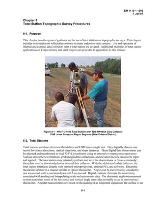
  • 1. EM 1110-1-1005 1 Jan 07 Chapter 8 Total Station Topographic Survey Procedures 8-1. Purpose This chapter provides general guidance on the use of total stations on topographic surveys. This chapter includes information on reflectorless/robotic systems and prism-only systems. Use and operation of internal and external data collectors with a total station are covered. Additional examples of total station applications on Corps military and civil projects are provided in appendices to this manual. Figure 8-1. Wild TC-1010 Total Station with TDS-HP48GX Data Collector 1998 Levee Survey at Bayou Segnette (New Orleans District) 8-2. Total Stations Total stations combine electronic theodolites and EDM into a single unit. They digitally observe and record horizontal directions, vertical directions, and slope distances. These digital data observations can be adjusted and transformed to local X-Y-Z coordinates using an internal or external microprocessor. Various atmospheric corrections, grid and geodetic corrections, and elevation factors can also be input and applied. The total station may internally perform and save the observations or (more commonly) these data may be downloaded to an external data collector. With the addition of a data collector, the total station interfaces directly with onboard microprocessors, external PCs, and software. Electronic theodolites operate in a manner similar to optical theodolites. Angles can be electronically encoded to one arc-second with a precision down to 0.5 arc-second. Digital readouts eliminate the uncertainty associated with reading and interpolating scale and micrometer data. The electronic angle-measurement system minimizes some of the horizontal and vertical angle errors that normally occur in conventional theodolites. Angular measurements are based on the reading of an integrated signal over the surface of an 8-1
  • 2. EM 1110-1-1005 1 Jan 07 electronic encoder that produces a mean angular value and completely eliminates the inaccuracies from eccentricity and circle graduation. These instruments also are equipped with a dual-axis compensator, which automatically corrects both horizontal and vertical angles for any deviation in the plumb line. Figure 8-2. Leica TCR-705 Reflectorless Total Station (Geodetic Services, Inc.) Figure 8-3. Trimble TSC and HP48 Data Collectors 8-2
  • 3. EM 1110-1-1005 1 Jan 07 a. The development of the total station has made it possible to accurately gather enormous amounts of survey measurements quickly. In the last 20 years, total stations and data collectors have become common field equipment, and have largely replaced the traditional survey methods that utilized transits, theodolites, and alidades. Digital theodolites and EDM instruments were perfected during the 1970s. In the early 1980’s the surveying instrument manufacturers introduced what has become the total station, redefining the term by creating an entirely electronic instrument that combined the heretofore separate digital theodolites and EDM devices. Directly storing direction and distance observations to a microprocessor helped eliminate many of the reading errors that can occur with an optical theodolite or traditional EDM where observations are hand recorded. Along with the advent of the electronic theodolite came the electronic data collector, thus minimizing both the reading errors and the writing errors. Modern total stations can measure a distance to an accuracy of better than 5 millimeters plus 1 part per million, with some variation depending on the type of reflecting surface or prism used. Electronic angles can be resolved to about one-half arc second, although models used for construction may have a resolution of only 30 seconds. In most land surveying situations, the normal crew size can be reduced to two persons when equipped with a standard total station, and one person when using robotic total stations. b. Traditionally, surveying has used analog methods of recording data. Digital data collection methods using electronic total stations are far more efficient. Total stations have dramatically increased the amount of topographic data that can be collected during a day and are well suited for topographic surveys in urban landscapes and busy construction sites. Modern total stations are also programmed for construction stakeout and highway centerline surveys. When proper procedures are performed, total stations have made trigonometric leveling nearly as accurate as many of the differential level techniques in areas possessing large relief landforms. Total station instruments and associated data collectors can quickly transfer 3D coordinates and are capable of storing unique mapping feature codes and other parameters which in the past could only be recorded on paper media such as field books. 8-3. Total Station Features and Operation There are less than a dozen manufacturers of total stations that commonly market in the US. Each manufacturer may have varied models, with optional features that can be tailored to local operating conditions, such as accuracy requirements, project size (EDM distances), and available crew size. Selection of a particular model, along with the associated data collector and CADD software, requires some research. A good place to start would be viewing periodic surveys by trade publications (see POB 2004a and POB 2004b in the references at Appendix A). Discussions with users at other Districts, local survey suppliers, and AE survey contractors are also recommended. Exhibitor demonstrations at state survey society meetings is another good place to observe and test new equipment. In some cases, vendors will offer to come to the district and demonstrate their equipment in your local working environment a. General operation. Total station surveys are performed similarly to transit-stadia or plane-table- alidade surveys. Total stations are set up over control points similarly to traditional transits, theodolites, or EDM. Most employ a three-screw, forced-centering Wild-type tribrach mount to fasten and align the total station with the tripod. Heavy wooden or fiberglass tripods are best for supporting total stations. Leveling over a point is performed no differently than traditional instrument methods. The tribrach is roughly centered over the point first using the standard tripod leg adjustment technique. The total station is then mounted in the three-pin tribrach and internally leveled using either level vials or electronic dual- axis methods, depending on the type of instrument. Either optical or laser plummets are used for final centering over a point. Some total stations provide out of level warnings to the operator. All plummets, optical or digital, should periodically be checked, adjusted, and calibrated. A conventional plumb bob provides such a check if used in ideal conditions. 8-3
  • 4. EM 1110-1-1005 1 Jan 07 b. Prism poles. A variety of target poles are used for the remote rod to which topographic observations are made. Both adjustable and fixed height poles are common--see Figure 8-4 below. Extendable rods (to 20 feet and higher) may be used--especially on beach profiling surveys and in canopy areas. For most applications, a retro-reflector prism is attached to the top of the prism pole such that there is no eccentric offset correction required. If not, then the retro-reflector offset correction must be determined and applied to observed distances. Use of a fixed height pole helps minimizes HR blunders. A shoe for the pole point may be needed in soft ground. A standard rod level is used to plumb the prism pole over a point. Many poles have built-in rod levels to facilitate plumbing the prism. Figure 8-4. Prism pole (Portland District) c. EDM range and accuracy. Ranges with standard prisms and reflectorless models vary widely between manufacturers. Both infrared and laser EDMs are used. Distance resolution is either pulsed (low accuracy) or phase comparison (typical ± 2 to ± 5 mm accuracy). One and three array prism ranges can vary from one mile to over 5 miles. Ranges of reflectorless total stations are specified relative to 90% and 18% Kodak grey cards, and can vary from 300 ft to over 3,000 ft. Reflectorless accuracies are not as good as prism accuracies given the variability of the reflecting terrain, and may therefore may not be suitable for more accurate surveys such as FEMA first floor elevation certificates. At the outer range limits, bicycle reflector tape or a prism rod with a retroreflector may be needed. Refer to POB 2004a for details on reported range and accuracy specifications by individual manufacturers. 8-4
  • 5. EM 1110-1-1005 1 Jan 07 d. Instrument controls. Focus and plate control tangent and locking screws vary widely between total station brands. A 30X optical zoom is common on most total stations. These controls should be operated in accordance with the manufacturer’s instructions. . e. Cost. Total station costs obviously will vary with the accuracy and added features. A simple digital theodolite (no data collection) will cost less than $1,500. A basic total station survey package (including tripod and prism pole) will cost about $7,500 and reflectorless or robotic units can cost upwards of $20,000. A data collector and software must be purchased separately--a $1,500 to $4,000 additional cost. A field laptop computer will run $2,000 to $3,000. Miscellaneous survey equipment can easily exceed another $3,000--e.g., extra tripods, total station batteries, 25-ft telescoping rod, additional prisms, magnetic locater, etc. f. Angular accuracy. Angle standard errors range from ± 1” to ± 5” based on a Direct and Reverse set. Less accurate models are available for construction layout application--e.g., 1-minute instruments. See POB 2004a for additional specifications on collimation corrections, orientation options, and plate vial bubble sensitivities for various units. Refer to any of the texts listed in Appendix A-2 for detailed descriptions of theodolite and total station alignment and calibration requirements. g. Data collectors. (see Chapter 6). h. Other features. Other factors to be considered in the selection of a particular total station include: robotic search controls, measurement time, integrated laser scanners, integrated GPS, internal digital camera, internal data storage capacity, internal COGO and stakeout capabilities, compatibility with existing data collector (if not purchased with the total station), weight (including batteries and battery life), ease of operation, and training needs. Figure 8-5. TOPCON GPT-8200 Series Reflectorless-Robotic Total Station can make reflectorless measurements out to 4,000 ft and prism measurements to 23,000 ft 8-4. Reflectorless and Robotic Total Stations Reflectorless and robotic total stations have an unlimited number of applications. They allow one-man survey crew operation. Reflectorless total stations can position objects that cannot be positioned with a 8-5
  • 6. EM 1110-1-1005 1 Jan 07 reflector prism, such as towers, tanks, roof eaves, overhead cables or power lines, overhead pipes, stockpiles, traffic areas, and potentially hazardous areas (unexploded ordinance). Robotic total stations have the advantage of one-man crew operation. In addition, they allow the instrument to be left unattended at secure sites. The instrumentman then records data at the rod/prism point, where a particular feature can be better identified. Typical units are shown in Figure 8-5 (above) and Figure 8-6 (below). Figure 8-6. Trimble 5600 DR Reflectorless-Robotic Total Station with ACU Survey Controller The data collector shown in the above figure is a Trimble ACU Survey Controller, which contains a color graphical display and uses a Windows CE operating system. This data collector can be used with the total station as shown, with a RTK topographic system, or as a robotic rover. 8-5. Field Equipment Inventory and Maintenance Modern electronic survey equipment requires surveyors to be maintenance conscious of their equipment. Special concerns include power sources and whether or not the instruments and accessories are accurately adjusted and in good repair. When setting up a crew to work with a total station and data collector, it is helpful to supply the party chief with a checklist to help the crew maintain its assigned equipment and handle the collected data upon returning to the office. It is also important that each crew be supplied with all necessary equipment and supplies. These should be stored in an organized and easily accessible manner. a. Typical equipment inventory for a two-man crew. Listed below is equipment list that would support a two-person crew, consisting of a party chief/rodperson and a notekeeper/instrument person. This should be a sufficient equipment inventory to meet the general needs of boundary, layout, and topographic surveys. It is assumed that this crew has a regular complement of supplies such as hammers, shovels, cutting tools, ribbon, stakes, lath, and safety equipment. • Total station • Data collector • Batteries for 14 hours of continuous operation plus backup supply • 3 tripods • 2 tribrachs • 2 target carriers 8-6
  • 7. EM 1110-1-1005 1 Jan 07 • 1 fixed height range pole and 1 adjustable pole • 2 target holders • 2 reflectors • 2 two-way radios b. Additional equipment. With this basic equipment inventory, a two-person field crew will be able to handle most survey tasks that are routinely encountered in day-to-day operations. An additional tripod, range pole, carrier, tribrach, and reflector would give the crew even greater flexibility, and allow them to handle many projects more efficiently. It is also helpful for the field crew to have a convenient place to store their assigned equipment. Crews should be equipped with briefcase-sized cases that will hold tribrachs, reflectors with holders, carriers, and target plates. A hard camera case or pistol case works well for this purpose. With all the components stored in one place, it makes inventory of the equipment easy and reduces the chance of equipment being left at the job site. This also allows for proper equipment maintenance. c. Equipment maintenance. The following checklist will aid each crew in properly maintaining and keeping inventory of their assigned equipment. At the end of each workday the party chief should check that the following duties have been performed: • Clean all reflectors and holders. A cotton swab dipped in alcohol should be used on the glass surfaces. A crew member can do this during the trip back to the office. • Clean tribrachs. They should be dusted daily. • Remove dust from all instruments. A soft paintbrush or a shaving brush works well. If an instrument has been exposed to moisture, thoroughly dry it and store in an open case. • Download the data collector to the computer. • Backup all files generated from the download and check the integrity of the backup files before erasing the field data from the data collector. • Clean batteries and connect to charger. Some batteries require a 14- to 20-hour charge, so one set of batteries may have to be charged while a second set is in operation. d. Battery maintenance. One of the biggest problems faced by the users of total stations with data collectors is maintaining an adequate power supply. Most total stations have small, removable, rechargeable Ni-Cad or gel-cell batteries. There are several factors that should be considered when assessing power needs: (1) Type of survey. A topographic survey usually entails much more data collection in a day than a boundary survey. Determine the number of measurements that you would normally make in a day and consult the manufacturer’s specifications to determine the number of shots you can expect from a fully charged new battery. In general, some 4 to 8 hours of continuous use is available, based on one EDM measurement every 30 seconds (POB 2004a). Larger batteries are available to extend observation time. (2) Age of batteries. Keep in mind that batteries will degrade over a period of time. This means that a new battery, with sufficient power for 500 measurements when new, may only be capable of 300 measurements after a year of use. With an inverter, extra backup batteries can be charged in the survey vehicle. (3) Time needed to charge batteries. Total station batteries take 3 to 5 hours to fully charge. Multiple battery chargers should be obtained in order to keep a sufficient supply of batteries on hand each morning. 8-7
  • 8. EM 1110-1-1005 1 Jan 07 (4) In addition to the proper assessment of power need, a record of the history and current status of the power supply should be readily available. When batteries begin to get weak there is generally a rapid deterioration in their performance. To monitor the performance of a particular battery record the serial number in a battery log book. If problems arise with a particular unit, check the log to see when the battery was purchased or when it was last recelled. Next try discharging and recharging the battery. If performance is still not up to speed, have it checked to determine the weak cell and replace it. If the battery was not new or was recelled in the last year, recell the entire unit. When one cell goes the next one is usually only a charge or two from failure. The cost of having a battery recelled is minimal when considering the cost of lost work time due to power failure. (5) Also record the date the battery was charged on the shipping label that is attached to the battery box. When the battery is fully used simply cross out the date, thus eliminating the confusion of not knowing which battery needs to be charged. Monitor the shelf time of the battery, and if it exceeds 10 days, recharge it. This keeps the power supply at peak performance. Always consult the operator’s manual for recharge specifications. e. Backup power. It is always a good idea to have backup power available for that last 15 minutes of work. Most manufacturers can provide cabling for backup to an automobile battery. Some can even supply a quick charge system that plugs into the cigarette lighter. Power pointers are: • Assess power needs for the particular job • Assess power usage of the equipment • Monitor performance of each battery • Monitor battery age, usage, and recell information • Have one day’s worth of backup power readily available 8-6. Total Station Job Planning An often-asked question when using a total station with a data collector is “How do I plan a project?” To answer this question, first examine the productivity standards expected of field crews. a. Most crews will make and record hundreds of observations per day. This includes any notes that must be put into the system to define what was measured. When creating productivity standards keep in mind that a learning curve is involved. Usually it takes a crew some four to five projects to become familiar with the equipment and the coding system to start reaching the potential productivity of the system. b. A two-person crew is most efficient when the nominal spacing of the measurements is less than 50 feet. When working within this distance the average rod person can acquire the next target during the time it takes the instrument operator to complete the measurement and input the codes to the data collector. The instrument operator usually spends 20 seconds (±) sighting a target, recording a measurement, and another 5-10 (or more) seconds coding the measurement. c. When the general spacing of the data exceeds 50 feet, having a second rod person will significantly increase productivity. A second rod person allows the crew to have a target available for measurement while the first rod person is moving. If the distance of the move is 50 feet or greater, the instrument will be idle with only one rod person. d. When dealing with strip topographic situations, it may be necessary to acquire data every 3 feet along the length of the job. In urban areas the data may seem to be denser, but the rights-of-way are 8-8
  • 9. EM 1110-1-1005 1 Jan 07 generally wider. Some feel that one measurement for every 3 feet of linear topography works very well for estimating purposes. Using this estimate, an average field crew can make and record between 350- 500 measurements or 1,000-1,500 feet of strip topography per day. A two-person crew equipped with recording total station and data collector can pick up 1,250 feet a day. Depending on the office/field reduction software being used, these data can produce both the planimetric and contour maps as well as transfer the data to an engineering design package with very little additional manipulation. 8-7. Total Station Error Sources All theodolites measure angles with some degree of imperfection. These imperfections result from the fact that no mechanical device can be manufactured with zero error. In the past very specific measuring techniques were taught and employed by surveyors to compensate for minor mechanical imperfections in theodolites. With the advent of electronic theodolites, the mechanical errors still exist but are related to in a different way. One must now do more than memorize techniques that compensate for errors. One must clearly understand the concepts behind the techniques and the adjustments for errors that electronic theodolites now make. The following paragraphs provide the major sources of error when using a theodolite and also the particular method employed to compensate for that error. a. Circle eccentricity. Circle eccentricity exists when the theoretical center of the mechanical axis of the theodolite does not coincide exactly with the center of the measuring circle. The amount of error corresponds to the degree of eccentricity and the part of the circle being read. When represented graphically circle eccentricity appears as a sine wave. Circle eccentricity in the horizontal circle can always be compensated for by measuring in both faces (opposite sides of the circle) and using the mean as a result. Vertical circle eccentricity cannot be compensated for in this manner since the circle moves with the telescope. More sophisticated techniques are required. (1) Some theodolites are individually tested to determine the sine curve for the circle error in that particular instrument. Then a correction factor is stored in ROM that adds or subtracts from each angle reading so that a corrected measurement is displayed. (2) Other instruments employ an angle-measuring system consisting of rotating glass circles that make a complete revolution for every angle measurement. These are scanned by fixed and moving light sensors. The glass circles are divided into equally spaced intervals which are diametrically scanned by the sensors. The amount of time it takes to input a reading into the processor is equal to one interval, thus only every alternate graduation is scanned. As a result, measurements are made and averaged for each circle measurement. This eliminates scale graduation and circle eccentricity error. b. Horizontal collimation error. Horizontal collimation error exists when the optical axis of the theodolite is not exactly perpendicular to the telescope axis. To test for horizontal collimation error, point to a target in face one then point back to the same target in face two; the difference in horizontal circle readings should be 180 degrees. Horizontal collimation error can always be corrected for by meaning the face one and face two pointings of the instrument. (1) Most electronic theodolites have a method to provide a field adjustment for horizontal collimation error. Again, the manual for each instrument provides detailed instruction on the use of this correction. (2) In some instruments, the correction stored for horizontal collimation error can affect only measurements on one side of the circle at a time. Therefore when the telescope is passed through zenith (the other side of the circle is being read), the horizontal circle reading will change by twice the collimation error. These instruments are functioning exactly as designed when this happens. 8-9
  • 10. EM 1110-1-1005 1 Jan 07 (3) When prolonging a line with an electronic theodolite, the instrument operator should either turn a 180-degree angle or plunge the telescope and turn the horizontal tangent so that the horizontal circle reading is the same as it was before plunging the telescope. c. Height of standards error. In order for the telescope to plunge through a truly vertical plane the telescope axis must be perpendicular to the standing axis. As stated before there is no such thing as perfection in the physical world. All theodolites have a certain degree of error caused by imperfect positioning of the telescope axis. Generally, determination of this error should be accomplished by a qualified technician because horizontal collimation and height of standards errors interrelate and can magnify or offset one another. Horizontal collimation error is usually eliminated before checking for height of standards. Height of standards error is checked by pointing to a scale the same zenith angle above a 90-degree zenith in "face-one" and "face-two." The scales should read the same in face one as in face two. d. Circle graduation error. In the past, circle graduation error was considered a major problem. For precise measurements surveyors advanced their circle on each successive set of angles so that circle graduation errors were “meaned out.” Current technology eliminates the problem of graduation errors. This is accomplished by photo-etching the graduations onto the glass circles and making a precise master circle and photographing it. An emulsion is then applied to the circle and a photo-reduced image of the master is projected onto the circle. The emulsion is removed and the glass circle has been etched with very precise graduations. e. Vertical circle error. It is important to check the vertical circle indexing adjustment on surveying instruments on a routine basis. When direct and indirect zenith angles are measured to the same point, the sum of the two angles should equal 360°. Over time, the sum of these two angles may diverge from 360° and consequently cause errors in vertical angle measurements. While averaging the direct and indirect zenith angles easily eliminates this error, on many jobs it may not be cost effective to make two readings. Acceptable accuracy may still be maintained for many applications with only a direct reading; however, as long as the index error is kept to a minimum by periodically performing a vertical adjustment, such as TOPCON's "Vertical Angle 0 Datum Adjustment." Most total stations are provided with some type of electronic adjustment to correct the vertical circle indexing error. This adjustment takes just a few seconds and will insure that you get good vertical angle readings with just one measurement. Consult the manufacturer's manual for instructions on making this adjustment. f. Pointing errors. Pointing errors are due to both human ability to point the instrument and environmental conditions limiting clear vision of the observed target. The best way to minimize pointing errors is to repeat the observation several times and use the average as the result. g. Uneven heating of the instrument. Direct sunlight can heat one side of the instrument enough to cause small errors. For the highest accuracy, utilize an umbrella or pick a shaded spot for the instrument. h. Vibrations. Avoid instrument locations that vibrate. Vibrations can cause the compensator to be unstable. i. Collimation errors. When sighting points a single time (e.g., direct position only) for elevations, check the instrument regularly for collimation errors. j. Vertical angles and elevations. When using total stations to measure precise elevations, the adjustment of the electronic tilt sensor and the reticule of the telescope becomes very important. An easy way to check the adjustment of these components is to set a baseline. A line close to the office with a 8-10
  • 11. EM 1110-1-1005 1 Jan 07 large difference in elevation will provide the best results. The baseline should be as long as the longest distance that will be measured to determine elevations with intermediate points at 100- to 200-ft intervals. Precise elevations of the points along the baseline should be measured by differential leveling. Set up the total station at one end of the baseline and measure the elevation of each point. Comparing the two sets of elevations provides a check on the accuracy and adjustment of the instrument. Accuracy requirements may dictate that more than one set of angles and distances is measured to each point. Some examples are distances over 600 feet, adverse weather conditions, and steep observations. k. Atmospheric corrections. Meteorological data corrections to observed EDM slope distances may be significant over longer distances. Usually for most topographic surveying over short distances, nominal (estimated) temperature and pressure data is acceptable for input into the data collector. Instruments used to measure atmospheric temperature and pressure must be periodically calibrated. This would include psychrometers and barometers. l. Optical plummet errors. The optical plummet or tribrachs must be periodically checked for misalignment. This would include total stations with laser plummets. m. Adjustment of prism poles. When using prism poles, precautions should be taken to ensure accurate measurements. A common problem encountered when using prism poles is the adjustment of the leveling bubble. Bubbles can be examined by establishing a check station under a doorway in the office. First, mark a point on the top of the doorway. Using a plumb bob, establish a point under the point on the doorway. If possible, use a center punch to make a dent or hole in both the upper and lower marks. The prism pole can now be placed into the check station and easily adjusted. n. Recording errors. The two most common errors are reading an angle incorrectly and/or entering incorrect information into the field book. Another common (and potentially disastrous) error is an incorrect instrument or rod height. Although electronic data collection has all but eliminated these errors, it is still possible for the surveyor to identify an object incorrectly, make a shot to the wrong spot, or input a bad target height (HR) or HI. For example, if the surveyor normally shoots a fire hydrant at the ground level, but for some reason shoots it on top of the operating nut, erroneous contours would result if the program recognized the fire hydrant as a ground shot and was not notified of this change in field procedure. o. Angles. As a rule, a surveyor will turn a doubled angle for move-ahead, traverse points, property corners, or other objects that require greater accuracy. On the other hand, single angles are all that are required for topographic shots. Refer to the total station operating instructions for repeating angle methods where required. p. Slope to grid and sea level EDM corrections. Slope distances will be reduced to horizontal distances in the data collector, and then reduced to a grid distance if a grid scale factor (or combined scale sea level factor) is input into the data collector. For most topographic survey applications involving short side shots, the grid scale factor is ignored (e.g., 1.000 is used). This would not be correct for control traverses covering larger distances. Scale factors can be obtained directly in CORPSCON. q. EDM calibration. All EDM instruments should be periodically (at least annually) checked over a NGS Calibration Baseline or a baseline established by local state surveying societies. 8-11
  • 12. EM 1110-1-1005 1 Jan 07 8-8. General Total Station Operating Procedures A set routine should be established for a survey crew to follow. Standard operating procedures should require that control points be measured and noted immediately on the data collector and/or in the field book after the instrument has been set up and leveled. This ensures that the observations to controlling points are established before any outside influences have had an opportunity to degrade the setup. In making observations for an extended period of time at a particular instrument location, reobserve the control points from time to time. This ensures that any data observed between the control shots are good, or that a problem has developed and appropriate action can be taken to remedy the situation. As a minimum, require survey crews to observe both vertical and horizontal control points at the beginning of each instrument setup and again before the instrument is picked up. One of the major advantages of using a total station equipped with data collection is that some errors previously attributed to blunders (e.g., transposition errors) can be minimized or eliminated. Even if the wrong reading is set on the horizontal circle in the field or the wrong elevation is used for the bench, the data itself may be precise. To make the data accurate, many software packages will allow the data to be rotated and/or adjusted as it is processed. The only way to assure that these corrections and/or observations have been accurately processed is to compare the data to control points. Without these observations in the recorded data, the orientation of that data will always be in question. The use of a total station with a data collector can be looked upon as two separate and distinct operations. The following procedure is typical of most total stations and data collectors: a. Total Station • If EDM is modular, mount it on instrument. • Connect data collector. • Set up and level instrument. • Turn on total station. • Set atmospheric correction (ppm). This should be done in the morning and at noon. • Set horizontal circle. • Set coordinates. • Observe backsight (check whether azimuth to backsight is 180 degrees from previous reading). • Observe backsight benchmark (obtain difference in elevation). This may require factoring in the height of reflector above benchmark. • Compute relative instrument height (benchmark elevation +/- difference in height). Note height of rod (HR) and note computations in field book. • Input Z (elevation) value in instrument or data collector. • Observe backsight benchmark (check elevation). • Invert and repeat (check elevation). b. Data Collector • Record date and job number. • Record crew number and instrument serial number. • Record field book number and page number. • Record instrument location (coordinates). • Record backsight azimuth. • Record standard rod height. • Record height of instrument. [Note: All the above information may also be recorded in a field book if necessary] 8-12
  • 13. EM 1110-1-1005 1 Jan 07 • Observe and record measurement to backsight benchmark. • Enter alpha or numeric descriptor of above point into data collector. • Observe and record measurement backsight benchmark or check benchmark (if setting benchmark, note in field book and repeat with instrument inverted). • Enter alpha or numeric descriptor of above point into data collector. • Observe and record measurement to backsight. • Enter alpha or numeric descriptor of above point into data collector. • Invert and repeat the above two steps. • Observe and record measurement to foresight. • Enter alpha or numeric descriptor of above point into data collector. • Invert and repeat the above two steps. • Observe and record measurement to side shot. • Enter alpha or numeric descriptor of above point into data collector (repeat the above two steps as needed). • When setup is complete, or at any appropriate time, repeat shots on vertical and horizontal control. Observe the displays and record in data collector. c. Precautionary guidance and recommendations on total stations. The following guidance from the CALTRANS Surveys Manual (CALTRANS Surveys Manual 2001-2004) is applicable to total station operation. • Never point the telescope directly at the sun as the sun’s rays may damage the diodes in an electronic distance measuring instrument (EDMI). • If possible, shade the instrument from direct sunlight as excess heat may reduce the range of the sender diodes in the EDMI. • To maintain maximum signal return at longer ranges, shade prisms from direct sunlight. • Avoid multiple unrelated prisms in the same field of view; this can cause blunders in distance observations. • Do not transmit with a two-way radio near the total station during EDMI measurements. • Most total stations are equipped to detect and correct various instrumental errors. If such errors exceed program limits, error codes will indicate the error. Consult the operator’s manual for exact procedures and error codes. • Do not carry tripod-mounted instruments over the shoulder. • Whenever possible, select instrument setup locations to minimize the exposure of the instrument operator, other members of the crew, and the instrument to danger. Select stable ground or footing for the tripod feet. Do not set an instrument directly in front of or behind a vehicle or piece of construction equipment that may suddenly move. • Don't leave instruments unprotected or unattended. • In the event that the instrument or any personnel are required to be in an area subject to traffic, protection procedures must be followed. 8-13
  • 14. EM 1110-1-1005 1 Jan 07 8-9. Total Station Angle Measurement and Traverse Techniques Most total stations provide a variety of methods for observing traverse or sideshot angles (or directions). Generally, three modes are available, depending on the angular accuracy required. The following modes are available on typical data collectors when configured with a total station. • Single - a single horizontal angle shot will be taken. • Directional - the sequence of shots to determine the horizontal angle for each point is as follows: direct to the backsight; direct to the foresight; reverse (invert) the scope; reverse to the backsight; reverse to the foresight. Multiple “sets” may be selected--e.g., two or four sets might be turned on a Third-Order traverse. • Repeating - multiple angles (windings) are taken to determine each horizontal angle. The value of the circle angle from each foresight reading is used as the circle angle for the next backsight; thus, accumulating the readings. a. Vertical angles. Similar options are available for vertical angles (or zenith distances). Either a single zenith distance is observed, or multiple (repeated) sets are observed in both circle faces. The number of positions (sets) is a function of the accuracy required. For topographic sideshots, a single zenith distance is all that is necessary. Multiple zenith distances (in face right and face left) should be observed when running a traverse with long distances between setups. b. Distance measurements. On most data collectors, options are available to take either single or multiple EDM distances. Multiple distances are then averaged for each shot. c. Tolerance alarms. When multiple sets are observed, a tolerance can be specified in the data collector to alert high misclosures in angles or distances. A tolerance factor on reflectorless observations will indicate potential erroneous settings or poor reflectivity at the target. d. Traverse procedures. Total station data collectors will automatically update traverse angle and distance observations at each sequential setup. Most collectors will compute angular and position misclosures, and perform a simple (Compass) traverse adjustment. More sophisticated data collectors can perform rigorous least squares adjustments, including vertical network adjustments. Adjusted traverse points are stored for use in densifying topography by radial methods. 8-10. Total Station Leveling Field Procedures Accurate trigonometric leveling is perhaps one of the most important applications of a total station. Trigonometric leveling error sources must be considered when using a total station to set vertical control or to define feature elevations. Table 8-1 below depicts relative elevation errors over varying distances and differing total station angular accuracies. Knowledge of the limitations of trigonometric leveling, together with means (instrumentation and procedures) to account for such limitations, is essential. Over short lines, total station trigonometric leveling can approach accuracies similar to those reached using a spirit level. Third-Order accuracy can be achieved over short lines, as indicated in Table 8-1 below. 8-14
  • 15. EM 1110-1-1005 1 Jan 07 Table 8-1. Elevation Errors (in feet) due to Errors in Trigonometric Zenith Angles Sight Distance Vertical Angle Uncertainty (seconds) 1 Sec 5 Sec 10 Sec 60 Sec 100 ft 0.0005 ft 0.0024 ft 0.005 ft 0.03 ft 200 0.0010 0.0048 0.010 0.06 400 0.0019 0.0097 0.019 0.12 500 0.0024 0.0121 0.024 0.15 1,000 0.0048 0.0242 0.049 0.29 To obtain Third-Order vertical accuracies with a total station, the following field procedures should be rigorously followed: • Careful setup and leveling • Use Face I and Face II observations • Reciprocal measurements • Take multiple observations • Protect instrument from sun and wind • Use proper targetry based on Inst/EDM configuration - Tilting target if necessary - Good quality reflectors - Correct prism offsets - Unambiguous target - Maintain targetry in good adjustment • Limited sight distances - 300 meters max - Reduce atmospheric-related error - Improves vertical angle accuracy • Accurately measure temperature and pressure - At least twice a day - If long steep line measurements at both ends, use averages • Watch for adverse refraction The following error sources impact the accuracy of trigonometric leveling with electronic total stations: • Instrument - Distances - Vertical angle accuracy - Vertical compensator important, dual axis compensation - No boost to vertical angle accuracy • Nature - Curvature and refraction - Temperature/pressure correction - Wind, sun, and weather 8-15
  • 16. EM 1110-1-1005 1 Jan 07 • Operator - Accurate pointing - Lots of measurements - Reciprocal measurements - Measure HI and HT or HR Errors due to curvature and refraction can become significant at distances greater than 500 ft. At 1,000 ft, a 0.02 ft error due to curvature and refraction is possible. At one mile, a 0.6 ft error results. An approximate formula used to correct for curvature and refraction was shown at Equation 3-7 in Chapter 3. h (feet) = 0.0206 (F) 2 (Eq 8-1) where h = combined correction for curvature and refraction in feet F = length of observed line in thousands of feet Data collectors should have built in options for making the above correction for each shot taken. Table 8-2 below shows the precision resulting from horizontal distance and vertical angular measurements as needed to resolve differences in elevations from trigonometric observation. Table 8-2. Combining Sources of Error over a 500-foot line Errors in Vertical Angle Measurement Source Type Nominal Amount Instrument accuracy Random +/- 3 sec Collimation Systematic +/- 3 sec Measure HI and HT Random +/- 0.005 to 0.1 ft C and R Systematic +/- 0.005 ft Hand-held prism pole Random +/- 0.005 ft 30-mm prism offs error Random +/- 3 mm Heat waves Random +/- 0.01 ft Unshaded instrument Random +/- 5 to 10 sec Combined angular and linear error is between -0.024 ft and 0.048 ft. Vertical angle precision for the 500-ft line is therefore in the range 1:10,000 and 1:210,000. Errors in Distance Measurement Source Type Nominal Amount Nominal accuracy Random +/-(5 mm + 5 ppm) Temp estimation Random +/- 10 degrees F Pressure estimation Random +/- 0.5 in Hg Prism and instr cal. Systematic +/- 2 mm Prism mispointing Random +/- 0.35 mm Hand-held prism pole Random +/- 5 ft (fore/ft lean) Combined error is between -0.0414 ft and +0.0546 ft. On this 500-ft line, this gives a range in precision of 1:9,000 to 1:12,000. 8-16
  • 17. EM 1110-1-1005 1 Jan 07 The following guidance from the Oregon Department of Transportation's Geometronics Unit (Oregon DOT 2000) applies to trigonometric elevation observations: • Due to the effects of curvature and refraction, the instrument to target distance must be kept relatively short. A good rule of thumb is not to exceed 1000 feet. • Make sure you understand your equipment’s capabilities. Instruments that can measure zenith angles and slope distances to a high order of accuracy will produce good trigonometric elevations. • Setup and level your instrument and target carefully. Measure the height of instrument and height of target accurately. • Measure several slope distances and use a representative or mean value. Make sure that your EDM is correcting for the appropriate atmospheric conditions. • Measure direct and reverse zenith angles, and use the adjusted value for your calculations. • For lines longer than 500 feet, correct for curvature and refraction. 8-11. Positioning Topographic Features with a Total Station Topographic features are usually cut in by multiple radial sideshots from a primary project control point. This is usually a straightforward process: the remote point is occupied with the prism pole, the HR and feature (code) recorded, and the angle and slope distance observed and recorded. If necessary, supplemental feature attributes may be added. The process is similar when using a reflectorless total station or robotic total station where the data collector is at the prism pole. The following sideshot sequence for the TDS-48GX is typical of most total stations: DIRECT SIDE SHOTS: => P-SHF “MAIN” => enter “J” [trav/side shot] => enter “HR” [height of reflector ... eg “5.0”] => SIDES (measures side shot point) => enter side shot descriptor plus attributes eg “CTR TWR GRD” “TOP OF TWR” => press ENTER => [repeat for additional side shots] The following Figure 8-7 shows 305 radial total station observations made during a survey at Fort McCoy by the Louisville District. These terrestrial radial observations are in green. Each of the five occupied points was established by fast static GPS observations from the local NSRS point on the installation--a point about a half mile to the north as shown in the lower left insert box on the TGO plate. In addition to the radial total station observations, some 106 RTK topographic points were shot on the easterly side of the site--as indicated in blue radials from the primary GPS base station. 8-17
  • 18. EM 1110-1-1005 1 Jan 07 Figure 8-7. Direct radial side shots with a Total Station and RTK control surveys at Fort McCoy Range a. Off center sideshots. Quite often objects cannot be directly occupied with a prism pole or targeted with a reflectorless total station. Off center (or eccentric) corrections are automatically available in most data collectors to cover these situations. Offset cases include trees or circular tanks where only a point on the circumference can be sighted, high objects that are beyond the reach of a prism pole, or invert elevations. The following off center options taken from the TDS-48GX data collector are typical of most data collectors. The "Off Center Shot Menu" covers five common situations that are encountered in the field when it is not convenient or not possible for the rod to occupy the point that needs to be stored. Those five situations are selected from the Off Center Shot menu. The Offset routines require that the data is collected as Zenith angles and Slope distances. The Traverse / sideshot screen will be automatically set to this mode when an offset shot routine is used. HORIZONTAL ANGLE OFFSET SCREEN This screen allows you to shoot the center of a large object such as a big tree. HORIZONTAL DISTANCE OFFSET SCREEN The Horizontal Distance Offset routine allows you to collect a point that is in-line with the rod but on which the rodman cannot occupy; e.g., the middle of a river. To use this routine, place the rod in line 8-18
  • 19. EM 1110-1-1005 1 Jan 07 with where the point should be placed. Shoot to the rod and enter the distance to add to the measured slope distance. Enter a negative distance to subtract from the slope distance. VERTICAL ANGLE OFFSET SCREEN The purpose of the Vertical Angle Offset Screen is to allow you to store a point that is too high for the rod; e.g., the cross-member of a power pole. This routine is used by placing the rod directly above or below the desired point and shooting the rod. Then, move the scope up or down to sight the true point, and press [ZEN] key to read the zenith angle. RIGHT ANGLE OFFSET SCREEN The Right Angle Offset Screen allows you to shoot a point that is at a right angle to your rod position; e.g., around the corner of a building. Place the rod at a 90° offset to the point you want to store. Shoot the rod and enter the offset distance. From the Instrument man’s point of view, enter + for offsets to the right of the rod and - for offsets to the left of the rod. VERTICAL DISTANCE OFFSET SCREEN The purpose of the Vertical Distance Offset Screen is to allow you to collect data for a point that you cannot obtain the zenith angle on, but to which you can measure the vertical distance; e.g., down a manhole. Place the rod above or below the desired point and shoot the rod. Then enter the distance to the actual point: + for up and - for down. b. Horizontal distance offset example. The following is an example of applying a horizontal offset to a target. In this example, the target is a Leica GPS antenna mounted in a tribrach atop a tripod-- see sketch at Figure 8-8. The antenna is set over a PK nail marked point. The Total station sights and measures a slope distance to the outside horizontal edge of the antenna--to a point horizontal with the antenna phase center. From published measurements of the GPS antenna, the distance from the outside of the antenna to the phase center is 0.330 feet. This is the offset distance entered into the data collector--a positive value since the offset must be added to the measured slope distance. The following sequence is used to perform a horizontal offset measurement on the TDS 48GX: HORIZONTAL DISTANCE OFFSET: => P-SHF “HDOFF” => enter offset distance ... eg radius of cir object [“+0.330 ft” for Leica antenna] => CNTR [takes shot at center face of object & adds offset] => ENTER => enter side shot description [eg “CENTER OF TANK” CTR TWR” “PK_NAIL”] The following data collector string illustrates the raw data saved for a horizontal offset distance sequence- -in this example a +0.330 ft offset. The second line in the string is the initial shot on the edge of the antenna. The horizontal angle is zero since this is the backsight for a default local coordinate system with the instrument set at 5,000-5,000-100. The fourth line (“SS”) is the offset corrected zenith distance and slope distance to the center of the antenna. Both the zenith distance and slope distance are larger to account for the offset. The last line (Sideshot 2) is the solved coordinates for the center of the GPS antenna at the station mark (a PK nail) -- HD offset OF,AR0.0000,ZE89.3505,SD47.427 initial horiz angle, zenith dir, & slope distance OF,DD0.330 horizontal offset distance of 0.330 feet SS,OP1,FP2,AR0.00000,ZE89.35153,SD47.757,--PK NAIL offseted sideshot to Point 2 2, 5047.755754, 5000.000000, 100.053746, PK NAIL solved coordinates Point 2 8-19
  • 20. EM 1110-1-1005 1 Jan 07 Offset = 0.330 ft s = 47.427 ft Circular object Total Station with known (measured) radius Figure 8-8. Horizontal distance offset measurement to circular object (pole, tree, tank) c. Vertical angle offset measurement. The following is an example of observing a vertical angle offset. In this example, a reflectorless total station is attempting to measure the elevation at the top of a 640-ft antenna--see sketch at Figure 8-9. Since this distance is beyond the range of the reflectorless return, or the object at the top does not provide sufficient reflectivity, an offset angle observation is required to obtain the elevation. The following sequence is used to perform a vertical angle offset measurement on the TDS 48GX: VERTICAL ANGLE OFFSET SHOTS: => P-SHF “VAOFF” => (sight reflector or reflectorless return point at bottom of object) => CNTR (measures) => (sight top of antenna) => ZEN (computes elev of top) In the example TDS-48GX raw data string below, the total station is set over an arbitrary coordinate point (“PK_NS-1”-10,000 ft-10,000 ft-100 ft), with an HI = 5.39 ft. An intermediate point on the tower directly below the highest-most point is selected at which a reflectorless slope distance can be made. On the second line of the string below, observations to the intermediate point are: horizontal angle right (AR) of 338º 00’ 40”, zenith distance of 31º 39’ 30”, and a slope distance of 329.52 ft. The instrument is then elevated to point on the top of the antenna--a zenith distance of 15º 14’ 35” is observed. (For such a high vertical angle, a 90-degree solar prism is needed for the eyepiece). The final corrected “SS” line has computed the slope distance as 657.81 ft to the top of the antenna, and the solved X-Y-Z coordinates of the antenna are shown in the last line. The elevation of the antenna is 640.06 ft above the elevation of the total station point (assumed elevation 100.0 ft). OC,OP1,N 10000.0,E 10000.0,EL100.0,--PK_NS-1 ... LS,HI5.39 OF,AR338.0040,ZE31.3930,SD329.520659 OF,ZE15.1435,--Vert Angle Offset SS,OP1,FP11,AR338.0040,ZE15.1435,SD657.818349,--TOP ANTENNA 11,10160.3689,9935.2429,740.0658,TOP ANTENNA solved elevation 8-20
  • 21. EM 1110-1-1005 1 Jan 07 Computed elevation 740.06 ft Zenith Distance to top point on structure 15º 14’ 35” ) d ute “Vertical Angle Offset” mp (co 1ft 7.8 65 Zenith Distance to reflected point s= on structure 31º 39’ 30” ft 52 9. 32 = s HI = 5.39 ft Assumed elevation 100.00 ft Figure 8-9. Vertical Angle Offset 8-21