
Recomendados
Recomendados
Más contenido relacionado
La actualidad más candente
La actualidad más candente (20)
Similar a Stress shielding in proximal tibia of a stemmed prosthesis
Similar a Stress shielding in proximal tibia of a stemmed prosthesis (20)
Más de Hiren Divecha
Más de Hiren Divecha (18)
Último
Último (20)
Stress shielding in proximal tibia of a stemmed prosthesis
- 1. Cardiff School of Engineering Coursework Cover Sheet Personal Details Student No: 1056984 Family Name: Divecha First Name: Hiren Personal Tutor: Prof Sam Davies Discipline: MMM Module Details Module Name: Engineering Theory 1 Module No: ENT536 Coursework Title: Stress shielding in the proximal tibia of a stemmed knee prosthesis is a major problem Lecturer: Dr D O’Doherty Submission Deadline: 8/1/2011 Declaration I hereby declare that, except where I have made clear and full reference to the work of others, this submission, and all the material (e.g. text, pictures, diagrams) contained in it, is my own work, has not previously been submitted for assessment, and I have not knowingly allowed it to be copied by another student. In the case of group projects, the contribution of group members has been appropriately quantified. I understand that deceiving, or attempting to deceive, examiners by passing off the work of another as my own is plagiarism. I also understand that plagiarising another's work, or knowingly allowing another student to plagiarise from my work, is against University Regulations and that doing so will result in loss of marks and disciplinary proceedings. I understand and agree that the University’s plagiarism software ‘Turnitin’ may be used to check the originality of the submitted coursework. Signed: …..…………………………………….………... Date: ………………………
- 2. Stress shielding in the proximal tibia of a stemmed knee prosthesis is a major problem Hiren Maganlal Divecha Candidate Number: 1056984 ENT536 – Engineering Theory 1 Abstract Stemmed tibial prostheses are used in revision total knee replacements as a means of by-passing areas of bony deficiency in the proximal tibia. They allow for maintenance of proper alignment and provide distal fixation where there is good bone stock. An unfortunate side-effect of using intra-medullary stemmed prostheses is stress shielding. This occurs because the stem is much stiffer than surrounding bone and therefore takes a greater proportion of the axial load, leaving the surrounding bone stress shielded. As a result, this bone will gradually resorb as it does not experience mechanical loading sufficient to stimulate positive remodelling. The magnitude of this stress shielding shall be explored, as well as modifications to the prosthesis that can reduce its magnitude. 1
- 3. Table of Contents Abstract .............................................................................................................................................. 1 1. Introduction ...................................................................................................................... 3 2. Stress analyses .................................................................................................................. 4 a. Proximal tibia without prosthesis .......................................................................................... 7 b. Influence of stem material ..................................................................................................... 8 c. Influence of stem diameter .................................................................................................... 9 d. Use of a hollow tibial stemmed prosthesis .......................................................................... 10 e. Analysis of an “ideal” material for a stemmed tibial prosthesis .......................................... 11 3. Discussion ........................................................................................................................ 12 4. Conclusion ....................................................................................................................... 18 5. References....................................................................................................................... 19 6. Appendices ...................................................................................................................... 21 a. Appendix 1 – Nomenclature ................................................................................................ 21 b. Appendix 2 – Abbreviations ................................................................................................. 21 2
- 4. 1. Introduction Stemmed tibial prostheses are used mainly in revision total knee replacement (TKR) surgery. Prosthesis fixation and alignment using a standard non-stemmed tibial component would be poor in the revision TKR due to bone loss/ defects that arise as a result of prosthetic loosening or osteolysis. The function of the stem is to provide better fixation, allow for maintenance of correct alignment and off-load/ bypass bony deficiencies (Bourne & Crawford, 1998) (Mabry & Hanssen, 2007). An unfortunate side-effect of using stemmed prostheses is stress shielding. Stress shielding occurs around implants whereby the implant load-shares with the surrounding bone. This results in reduced stresses within the bone and results in osteopenia. The mechanism accounting for this is conceptualised in Wolff’s law (Wolff, 1892) translated to English (Maquet & Furlong, 1986): Every change in the function of a bone is followed by certain definite changes in its internal architecture and its external conformation. Thus, by off-loading the proximal tibia, bone density decreases as there is less stimulation of osteoblastic activity (i.e.: bone formation) compared to osteoclastic activity (i.e.: bone resorption). The resulting osteopenia has the following consequences: 1. Loss of fixation of prosthesis, leading to progressive prosthesis loosening and migration 2. Increased bone loss/ bone defects which makes further revision surgery even more difficult (often requiring bone grafting, metallic augments or even custom prostheses) 3. Increased risk of peri-prosthetic fracture The following analysis aims to demonstrate the magnitude of stress shielding that occurs in the proximal tibia with a stemmed tibial prosthesis in situ. 3
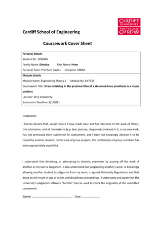
- 5. 2. Stress analyses In these analyses, the following assumptions are made: 1. The proximal tibia is modelled as a cylinder. In reality, the metaphysis is almost conical with an elliptical cross-section and narrows at the metaphyseal-diaphyseal junction. The diaphysis is prismoid in cross-section. 2. Bone is made up of outer cortical bone and inner cancellous bone 3. The prosthesis is firmly bonded to the bone via a cement mantle and behaves as a composite, thus in a state of iso-strain 4. The cement mantle (polymethylmethacrylate – PMMA) has a constant thickness of 1mm 5. The prosthesis experiences a compressive axial load (F) of three times body weight (i.e.: for a 70kg subject; 3 x 70 x 9.81 = 2060N), based on modelled maximum tibial plateau contact values in the terminal stance phase of the gait cycle (Wehner, Claes, & Simon, 2009) 6. This axial force is taken as acting through the centre of the tibial plate and stem. Thus no bending moments are experienced 7. Interface, radial, hoop and shear stresses are ignored Figure 1 demonstrates a cross-section of the modelled proximal tibia with the cemented tibial stem in situ including the diameters of each constituent used henceforth. 4
- 6. Stem (0.013m) Cement Mantle (0.015m) Cancellous Bone (0.024m) Cortical Bone (0.03m) Figure 1: Diagrammatic representation of cross-section of proximal tibia with cemented stem in situ (outer diameters in brackets) 5
- 7. The proportion of the total axial load (F) experienced by each constituent can be determined by that constituent’s relative axial rigidity (ϵx) based on the cross-sectional area (A) and Young’s modulus of elasticity (E), as demonstrated below (Huiskes, 1984) (Huiskes, 1984) (Huiskes, 1991): The cross-sectional area of a hollow circle is given by the following equation (rx is the outer diameter; ry is the inner diameter): Thus, the proportion of the axial load (Lx) experienced by each constituent is given by: 6
- 8. a. Proximal tibia without prosthesis Before analysing the situation with a prosthesis in situ, the distribution of load, and thus stress, between cortical and cancellous bone shall be analysed. Table 1 shows the Young’s moduli, cross- sectional areas, relative axial rigidities, proportion of load and stress experienced by cortical and cancellous bone with an axial load (F) of 2060N. Thus in the natural situation, the cortical bone takes the majority of the axial load. Young’s Modulus, Cross-sectional Relative axial Load, L /N Stress, σ /MPa E /GPa Area, A /m2 rigidity, ϵ Cortex 12 0.000254 0.985 2030 79.92 Cancellous 0.1 0.000452 0.015 30 0.66 Table 1: Analysis without prosthesis 7
- 9. b. Influence of stem material The following analyses shall demonstrate the change in stress distribution amongst the constituents of this composite model with a cemented, stemmed tibial prosthesis in situ. The influence of the material used for the prosthesis shall also be demonstrated. The most common materials used in orthopaedic prostheses are cobalt-chrome (Co-Cr) and titanium alloys (Ti-6Al- 4V; referred to as Ti henceforth). The stress distribution between the constituents is demonstrated for Co-Cr and Ti stems in Tables 2 and 3 respectively. Young’s Cross- Relative axial Load, L/N Stress, σ/MPa Modulus, sectional rigidity, ϵ E/GPa Area, A/m2 Cortex 12 0.000254 0.0943 194.25 7.65 Cancellous 0.1 0.000276 0.0009 1.75 0.06 Cement 2.3 0.000044 0.0031 6.44 1.46 (PMMA) Stem (Co-Cr) 220 0.000133 0.9017 1857.56 139.67 Table 2: Analysis with Co-Cr prosthesis Young’s Cross- Relative axial Load, L/N Stress, σ/MPa Modulus, sectional rigidity, ϵ E/GPa Area, A/m2 Cortex 12 0.000254 0.1668 343.48 13.52 Cancellous 0.1 0.000276 0.0015 3.10 0.11 Cement 2.3 0.000044 0.0055 11.38 2.59 (PMMA) Stem (Ti) 114 0.000133 0.8262 1702.04 127.97 Table 3: Analysis with Ti prosthesis 8
- 10. c. Influence of stem diameter Reducing the stem’s diameter will result in a reduced relative axial rigidity and therefore lessen the stress shielding effect. The stress experienced by the stem will also increase and consideration must be made in ensuring the stem is adequately strong to endure in vivo loading without failure. Table 4 below shows an analysis using a Ti stem of diameter 0.008m. Young’s Cross- Relative axial Load, L/N Stress, σ/MPa Modulus, sectional rigidity, ϵ E/GPa Area, A/m2 Cortex 12 0.000254 0.3436 707.88 27.82 Cancellous 0.1 0.000374 0.0042 8.67 0.23 Cement 2.3 0.000028 0.0073 15.08 5.33 (PMMA) Stem (Ti) 114 0.000050 0.6448 1328.37 264.27 Table 4: Analysis with reduced diameter Ti prosthesis (0.008m) 9
- 11. d. Use of a hollow tibial stemmed prosthesis If the stem is hollow, the axial rigidity of the stem (EA) will be reduced and will reduce further as the inner diameter approaches the outer diameter. Thus, the stem will theoretically take less of the overall axial load resulting in less stress shielding of the proximal tibial bone. This is demonstrated in Table 5 below with the stem being made of Ti with an outer diameter of 0.013m and an inner diameter of 0.01m. The cross-sectional area of the hollow stem is: Young’s Cross- Relative axial Load, L/N Stress, σ/MPa Modulus, sectional rigidity, ϵ E/GPa Area, A/m2 Cortex 12 0.000254 0.3266 672.78 26.49 Cancellous 0.1 0.000276 0.0030 6.09 0.22 Cement 2.3 0.000044 0.0108 22.34 5.08 (PMMA) Stem (Ti) 114 0.000054 0.6596 1358.79 251.63 Table 5: Analysis with hollow Ti stem 10
- 12. e. Analysis of an “ideal” material for a stemmed tibial prosthesis Another approach to developing an ideal stemmed tibial prosthesis is to determine the Young’s modulus of a theoretical material that would result in the cortical bone taking 80% of the overall load (i.e.: a relative axial rigidity ϵcortex of 0.80). This analysis shall be performed for a Ti stem with an outer diameter of 0.013m. Table 6 below shows results of the relative loads and stress distribution using a stem of 0.013m diameter with a Young’s modulus of 4.76GPa. Young’s Cross- Relative axial Load, L/N Stress, σ/MPa Modulus, sectional rigidity, ϵ E/GPa Area, A/m2 Cortex 12 0.000254 0.8 1648.00 64.88 Cancellous 0.1 0.000276 0.007244 14.92 0.54 Cement 2.3 0.000044 0.026562 54.72 12.44 (PMMA) Theoretical 4.76 0.000133 0.166163 342.30 25.74 Stem Table 6: Analysis to allow 80% load through cortical bone 11
- 13. 3. Discussion In the natural situation, the cortical bone takes the majority of axial load transferred from the tibial plateau. The introduction of a stemmed tibial prosthesis results in the proximal tibial bone (cortex and cancellous) becoming stress shielded as the relative rigidity of the stemmed component is much greater than that of the bone. The stem therefore takes a greater proportion of axial load. A comparison of the results obtained from the analyses performed above are summarised in Figure 2. 350 300 250 Stress (MPa) 200 150 100 Stem 50 Cortex 0 Figure 2: Chart comparing stress experienced in cortex and stem for different stem analyses 12
- 14. Factors that can be modified or manipulated to reduce the stress shielding effect of the stemmed tibial prosthesis include: 1. Reduced stiffness of the material used for the stem (i.e.: lower Young’s modulus) 2. Reduced diameter of the stem 3. Making the stem hollow – this results in a reduced cross-sectional area of the stem which reduces the relative axial rigidity but also increases the stress in the stem compared to a solid stem of the same diameter The results obtained with this simplified analysis show a reduction of stress in the cortex from 79.92MPa in the native tibia to 7.65MPa with a Co-Cr stem, 13.52MPa with a Ti stem, 26.49MPa with a hollow Ti stem and 64.88MPa using a solid stem made of a theoretical material with a low Young’s modulus (4.76GPa). Examples of materials with a low Young’s modulus in this range include polystyrene (3.5GPa), nylon (2-4GPa), acrylics (3.2GPa), polyvinylchloride (3.4GPa) polyethylene (0.18-1.6GPa). Such materials would not be strong enough to accommodate the expected loads transferred and would easily undergo deformation and failure in vivo. Thus, there is a trade-off in attempting to reduce the relative axial rigidity of the stem. The strength of the stem will also reduce and eventually a point will be reached where the stem’s primary functions (maintaining correct alignment, providing solid fixation, by-passing deficient proximal tibia) will be compromised resulting in early failure. Describing the proportion of load shared by the various constituents in this model using this simplistic analysis gives an estimate to the in vivo situation. Proximally at the joint itself, the axial force is transferred to the tibial plate. As shown in Figure 3 below and described by R. Huiskes (Huiskes, 1984) (Huiskes, 1984), the majority of this force is transferred to the stem with a smaller proportion (dependent on the relative axial rigidity) being transferred to the surrounding bone beneath the plate (compared to the situation where there is no plate such as in an non-collared 13
- 15. femoral stem – here there is a proximal load transfer zone between the stem and bone). Through the length of the stem, the proportion of load borne by the stem stays proportional to its relative axial rigidity. The length of the proximal and distal load transfer zones is dependent on λn which refers to the axial fixation exponent and depends on relative axial rigidities and characteristics of the cement layer. The stem tip is an area of high stress concentration and the load is transferred across to the surrounding bone which will experience the full load (F) i.e.: not experience stress shielding. Figure 3: Load transfer characteristics of a straight stem cemented in bone as depicted on p. 398 (Huiskes, 1991). 14
- 16. As per Wolff’s law, bone remodelling is driven, in part, by mechanical loading (stress). The stress shielding experienced around the tibial stem results in osteopenia due to an imbalance between osteoblastic and osteoclastic activity, resulting in net bone resorption. Clinically, this effect can be investigated using dual energy x-ray absorpitometry (DEXA) which calculates the bone mineral density (BMD). Lonner et al found a significantly reduced BMD of the proximal tibia in cemented stems (relative to the patient’s unoperated contra-lateral limb) compared to non-stemmed prostheses at an average follow-up of 94 months indicating significant stress shielding (Lonner, Klotz, Levitz, & Lotke, 2001). Interestingly, Abu-Rajab et al found no difference in relative BMD when comparing cemented versus cementless stemmed tibial prostheses at 2 years follow-up (Abu-Rajab, Watson, Walker, Roberts, Gallacher, & Meek, 2006) indicating that the use of cement may not influence the amount of stress shielding. Sathappan et al found no significant difference in BMD at an average of 87.7 months post-operative when comparing 23 standard with 18 stemmed tibial prostheses. They hypothesised that this may be due to the senior author’s preference for only cementing the tibial tray and allowing a press-fit cementless fixation of the stem itself, thus reducing the stress shielding effect over the length of the press-fit stem (Sathappan, Pang, Manoj, Ashwin, & Satku, 2009). Stress/ strain gauge analyses can be performed in vitro to analyse the stress shielding effect, such as that performed by Bourne and Finlay on cadaveric tibiae, which showed significant proximal tibial stress shielding over the length of the stem (Bourne & Finlay, 1986). In a cadaveric strain gauge analysis, Jazrawi et al found that larger diameter and longer press fit tibial stems significantly improved stability with improved resistance to lift off of the tibial tray and to shear stresses. There was a statistically non-significant trend towards increased proximal stress shielding with long cemented stems, though stability was greater in this group (Jazrawi, Bai, Kummer, Hiebert, & Stuchin, 2001). A more accurate method of determining stress distribution is 15
- 17. using finite element analysis (FEA). This is a computerised method that entails the three dimensional modelling of the object to be studied with nodes that form a mesh frame. Specific material mechanical properties can be assigned to the appropriate regions (bone, implant, cement) and the loading conditions can be specified. The resulting calculations will reveal a stress or strain distribution over the three dimensional model. Completo et al (Completo, Talaia, Fonseca, & Simoes, 2009) performed a FEA comparison of various stem designs and found that Co-Cr long stems (0.11m) had the greatest proximal stress shielding effect (82% of the stress in an intact tibia). With the long Ti stem (0.11m), there was proximal stress shielding of 79% which reduced to 0% around the mid-stem region. They found a 700% increase in stress at the stem tip. The short Ti stem (0.05m) did not experience any proximal stress shielding but did have a 450% increase in stress at the stem tip. A further analysis of a long Ti stem (0.095m) with a 0.015m polyethylene (PE) tip revealed no change in the proximal stress shielding, but a significant reduction in stress concentration at the stem tip to 150%. Increased stress concentrations at the tip of the stem may explain the phenomenon of end-of- stem pain and may theoretically increase the risk of a peri-prosthetic fracture (Barrack, Stanley, Burt, & Hopkins, 2004) (Completo, Talaia, Fonseca, & Simoes, 2009). Other methods for reducing stress shielding include using a hollow stem. In a FEA study of cemented hip prostheses, Gross and Abel found an 18% increase in proximal femur bone stress (compared to a reference 0.01m solid stem) when using a 0.01m hollow stem with an inner diameter of 0.009m (Gross & Abel, 2001). This effect reduced as the inner diameter of the stem was reduced. 16
- 18. The analysis performed here is a simplistic approximation of the in vivo situation, which is made more complicated by the following variables that are not accounted for: 1. Three dimensional geometry 2. Non-uniform cement mantle and non-uniform bonding 3. Forces not considered – bending moments, shear stresses, hoop stresses, torsional stresses 4. Dynamic forces during gait 5. Contribution of ligament/ tendon loading Though a “perfect prosthesis” is far from reality, it certainly seems that FEA is the method of choice for designing and experimentally testing the effects of stress shielding in attempt to develop a suitable compromise. 17
- 19. 4. Conclusion Stemmed tibial prostheses are generally only used in revision TKR scenarios where there is significant bone loss. This is a difficult situation because in attempting to achieve a good, stable fixation of the implant, a long stem must be used to provide distal support (as the proximal tibia is deficient and must be by-passed, especially if it is grafted). This leads to stress-shielding of the proximal tibia, which is already deficient. This bone will not undergo positive bone remodelling and will resorb gradually. Biomechanically, this stress shielding effect can be quantified using static stress analyses (as above), in vitro stress / strain gauge analyses and, more accurately, with FEA. Whilst this effect can be reduced by using materials that are less stiff, reducing the diameter of the stem, using a shorter stem (thus shorter length of stress-shielded bone), using hollow stems and possibly by only cementing proximally beneath the tibial tray, a trade off will be reached where the strength of the prosthesis and its fixation may become compromised leading to earlier failure and possibly increased bony deficit in the process. 18
- 20. 5. References Abu-Rajab, R. B., Watson, W. S., Walker, B., Roberts, J., Gallacher, S. J., & Meek, R. M. (2006). Peri- prosthetic bone mineral density after total knee arthroplasty. Cemented versus cementless fixation. J Bone Surg Br , 88 (5), 606-613. Barrack, R. L., Stanley, T., Burt, M., & Hopkins, S. (2004). The effect of stem design on end-of-stem pain in revision total knee arthroplasty. J Arthroplasty , 19 (7), 119-124. Bourne, R. B., & Crawford, H. A. (1998). Principles of revision total knee arthroplasty. Orthop Clin North Am , 29 (2), 331-337. Bourne, R. B., & Finlay, J. B. (1986). The influence of tibial component intramedullary stems and implant-cortex contact on the strain distribution of the proximal tibia following total knee arthroplasty. An in vivo study. Clin Orthop Relat Res , 208, 95-99. Completo, A., Talaia, P., Fonseca, F., & Simoes, J. A. (2009). Relationship of design features of stemmed tibial knee prosthesis with stress shielding and end-of-stem pain. Materials & Design , 30 (4), 1391-1397. Gross, S., & Abel, E. W. (2001). A finite element analysis of hollow stemmed hip prostheses as a means of reducing stress shielding of the femur. J Biomech , 34 (8), 995-1003. Huiskes, R. (1991). Biomechanics of artificial-joint fixation. In V. C. Mow, & W. C. Hayes, Basic Orthopaedic Biomechanics (1st ed., pp. 375-442). New York: Raven Press Ltd. Huiskes, R. (1984). Design, fixation, and stress analysis of permanent orthopaedic implants: The hip joint. In P. Ducheyne, & G. W. Hastings (Eds.), Functional behavior of orthopaedic biomaterials (1st ed., Vol. II: Applications, pp. 121-162). Boca Raton: CRC Press Inc. 19
- 21. Huiskes, R. (1984). Principles and methods of solid biomechanics. In P. Ducheyne, & G. W. Hastings (Eds.), Functional behavior of orthopedic biomaterials (1st ed., Vol. I, pp. 51-97). Boca Raton: CRC Press Inc. Jazrawi, L. M., Bai, B., Kummer, F. J., Hiebert, R., & Stuchin, S. A. (2001). The effect of stem modularity and mode of fixation on tibial component stability in revision total knee arthroplasty. J Arthroplasty , 16 (6), 759-767. Lonner, J. H., Klotz, M., Levitz, C., & Lotke, P. A. (2001). Changes in bone density after cemented total knee arthroplasty. Influence of stem design. J Arthroplasty , 16 (1), 107-111. Mabry, T. M., & Hanssen, A. D. (2007). The role of stems and augments for bone loss in revision knee arthroplasty. J of Arthroplasty , 22 (4), 56-60. Maquet, P., & Furlong, R. (1986). The law of bone remodelling. Berlin: Springer-Verlag. Sathappan, S. S., Pang, H., Manoj, A., Ashwin, T., & Satku, K. (2009). Does stress shielding occur with the use of long-stem prosthesis in total knee arthroplasty? Knee Surg Sports Traumatol Arthrosc , 17, 179-183. Wehner, T., Claes, L., & Simon, U. (2009). Internal loads in the human tibia during gait. Clin Biomech , 24 (3), 299-302. Wolff, J. (1892). Das gesetz der transformation der knochen. Berlin: Hirschwald. 20
- 22. 6. Appendices a. Appendix 1 – Nomenclature Symbol Quantity SI Unit L Axial load N E Young’s modulus of elasticity GPa A Cross-sectional area m2 ϵ Relative axial rigidity σ Stress MPa b. Appendix 2 – Abbreviations Abbreviation Full term TKR Total knee replacement FEA Finite element analysis Co-Cr Cobalt-chrome alloy Ti Titanium alloy (Ti-6Al-4V) PE Polyethylene PMMA Polymethylmethacrylate DEXA Dual Energy X-ray Absorpitometry BMD Bone Mineral Density 21