Lu2520442048
•
0 recomendaciones•205 vistas

IJERA (International journal of Engineering Research and Applications) is International online, ... peer reviewed journal. For more detail or submit your article, please visit www.ijera.com

Recomendados
Recomendados
Más contenido relacionado
La actualidad más candente
La actualidad más candente (13)
Destacado
Destacado (20)
Similar a Lu2520442048
Similar a Lu2520442048 (20)
Último
Último (20)
Lu2520442048
- 1. Ramanatha Dash, F.Anand Raju / International Journal of Engineering Research and Applications (IJERA) ISSN: 2248-9622 www.ijera.com Vol. 2, Issue 5, September- October 2012, pp.2044-2048 Buckling Behaviour Of Compression Loaded Composite Cylindrical Shells With Reinforced Cutouts Ramanatha Dash *, F.Anand Raju ** * PG Student, CAD/CAM, Siddharth Institute of Engineering & Technology (SIETK), Puttur - 517583 ** Department of Mechanical Engineering, SIETK College, Puttur, Chittoor Dist, Andhra Pradesh, INDIA. ABSTRACT In the recent times, Composite thin concentrations that can cause local buckling or cylindrical shells are most widely used structural premature material failures. In addition it is forms in Aerospace and Missile applications. In important to understand performance enhancements designing efficient and optimized shell structure, that can be obtained by using light weight fibre- they become increasingly sensitive to buckling. It reinforced composite materials. Fuethermore these is well known that the experimental display is structures experience compression loads during mainly attributed to geometrical imperfection vehicle operation and as a result, their buckling like damage in the structure, or ovality or local response and material failure characteristics must be thining of material etc. in missile and Airframe , understood and accurately predicted in order to the composite cylindrical shell structure is devlop efficient,safe design. generally provided with cutouts for accessing internal components during integration. The Many numerical and experimental studies cutouts invariably reduce the strength of the of the buckling behaviour of cylindrical shells have composite cylindrical shell and more specifically been conducted since the early 1900s.It took nearly the buckling load. It has been a design practice to 100 years to reach the point where improve strength by addition of reinforcement robust,measurement technologies were available that around cutouts. The cutout not only introduces could be used to conduct test-analysis correlations stress concentration but also significantly reduce that include the effect of initial geometric,material, buckling load. Which will results to eliminate the and manufacturing perfections and the effect of load Interlaminar and intralaminar failure by change introduction and support conditions.in addition ,the in material properties through dimensional use of advanced composite materials allows the computational analysis was carried out using designer to tailor the stiffness properties of the ANSYS as the preprocessing software and FE as structure to obtain a structurally efficient design. the solver and post processor. Thin walled cylindrical shells are found in many aerospace structural applications because of their Keywords: Acoustic, reinforcement, FEA high load carrying capacity and low structural weight.Many of these aerospace shell structures 1. INTRODUCTION: have cutouts or openings that serve as The composite is a combination of two or doors,windows, or access ports and thesr cutouts or more materials combine on a microscopic scale to openings often require some type of reinforcing give superior properties than original materials structure to control local structural deformations and include strength,fatigue life, stiffness ,temperature stress near the cutout.many studies have been dependent behaviour,corrosion resistance,thermal conducted which shows that a cutout in an isotropic insulation,wear resistance,thermal shell structure can have a significant effect on the conductivity,attractiveness,acoustical insulation and response of the shell.Towards this objectives, weight. The composites find its application in numerically predicted results that shows the effect of Aerospace,Defence,Automobiles,Machine tool, change in material properties of graphite/Epoxy Marine, Construction industry,chemical industry and composite shell with reinforcement configuration on biomedical equipments etc. In general structural the response of these shell structures are presented. discontiuities in the form of cutouts are inevitable in Results include the variation of Buckling factor, the design and construction particularly in the Deformation, Interlaminar shear stresses change in Aerospace industry.Thin-walled shell structures are Et/El, Gxy/El, and Gyz/El. a fundamental component found in Initially straight, then the direction of Aircraft,spacecraft, and launch vehicles. In most buckling will be very sensitive to any lateral force applications,these structural components contain applied to the middle of the card. If you push gently cutouts or openings that serve as doors,windows, or to the left on the middle of the card and then squeeze access ports, or used to reduce weight.often some it, it will buckle to the left. If you push gently to the type of reinforcement is used around a cutout to right and then squeeze, it will buckle to the right. eliminate local deformations and stress Once the card has begun to buckle in one direction it 2044 | P a g e
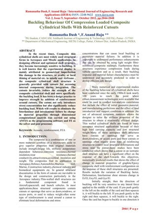
- 2. Ramanatha Dash, F.Anand Raju / International Journal of Engineering Research and Applications (IJERA) ISSN: 2248-9622 www.ijera.com Vol. 2, Issue 5, September- October 2012, pp.2044-2048 is difficult to force it in the other direction. In short, 2D-DRAWINGS a small lateral force applied to the card as an "input Fig 1, Fig 2 , Fig 3 & fig 4 shown below the signal" can control the direction of the large lateral finite element model of a composite shell with displacement produced as an "output signal" when centrally located square cutouts dimensions of a the card is buckled by a force applied from the top as 1*1mm. a "clock signal" 2.BUCKLING OF CYLINDRICAL SHELL: This buckling arrangement can be used to define logic operations. If one or more input forces are applied laterally to the midsection of the shell, then the midsection will be pushed either somewhat to the left or somewhat to the right, depending on the sum of the applied forces. When the large clocking force is applied, the initial direction of deformation will be continued, and with greater force. This can be viewed as a threshold device, for the output state is controlled by the sum of the input forces. Once buckled in one direction or the other, the shell will remain in that state and will be resistant to a change to the other stable state (in which it is buckled in the Fig1:.Front view of composite shell other direction). The cylindrical shell is uniformly Fig2: Composite shell with hole compressed in the axial directions,buckling symmetrical with respect to the axis of cylinder. The critical value of compressive force Ncr per unit length of the edge of the shell can be obtained by using the energy method. 2.1 FINITE ELEMENT MODEL: Fig3.Composite shell with reinforced hole Fig. shows the structural analysis of shells. 2045 | P a g e
- 3. Ramanatha Dash, F.Anand Raju / International Journal of Engineering Research and Applications (IJERA) ISSN: 2248-9622 www.ijera.com Vol. 2, Issue 5, September- October 2012, pp.2044-2048 Fig4.Top view of composite shell 2.2 DIMENSIONS OF A MODEL: Length of the shell =16 mm Fig Shell99 element geometry Radius of the shell =8mm Xij = Element x-axis if ESYS is applied. Thickness of shell =0.04mm X=Element x-axis if ESYS is supplied. No. of plies =8 LN= layer Number Dimension of cutout =1mm*1mm NL=Total number of Layers. 3. BOUNDARY CONDITIONS: 4.0 MESHING: The one end of the shell constrained all The results are studied to understand the Degree of freedom( Bottom ) and other end of the influence of cutouts on buckling strength of shell of shell is applied compressive load of 2000N(Top). same material and also the extent of improvement by providing reinforcement around cutouts. 3.1 SPECIFY MATERIAL PROPERTIES: (GRAPHITE/EPOXY) 4.1 WITHOUT REINFORCEMENT Longitudinal modulus,El = Composite shell without hole Composite shell with 127.46Gpa one hole Transverse modulus, Et = 11.3Gpa In-plane shear modulus,Gxy = 6Gpa In-plane shear modulus,Gyz = 3.514Gpa Major Possions ratio,v =0.30 3.2 SHELL99 ELEMENT DESCRIPTION: SHELL99 may be used for layered applications of a structural shell model. While SHELL99 does not havsome of the nonlinear capabilities of SHELL91, it usually has a smaller element formulation time. SHELL99 allows up to 250 layers. If more than 250 layers are required, a user-input constitutive matrix is available. The element has six degrees of freedom at each node: translations in the nodal x, y, and z directions and rotations about the nodal x, y, and z- axes. 2046 | P a g e
- 4. Ramanatha Dash, F.Anand Raju / International Journal of Engineering Research and Applications (IJERA) ISSN: 2248-9622 www.ijera.com Vol. 2, Issue 5, September- October 2012, pp.2044-2048 Composite shell with reinforcement of one, two Composite with two holes Composite shell with holes respectively four holes 4. RESULTS: CHANGE IN RATIO OF ET/EL TABLES Without With With Et/El hole 1hole 2holes with4holes 0.02 7.181 7.186 7.287 7.212 0.04 7.298 7.302 7.398 7.325 0.06 7.413 7.416 7.508 7.437 0.08 7.575 7.578 7.664 7.595 0.10 7.639 7.641 7.725 7.657 Table4.1 Variation of buckling factor with change in ratio of Et/El Deformation without hole Deformation with one hole Fig shows the interlaminar shear stress of shell with 7.8 one hole, the max, min interlaminar shear stress is 7.7 14.625,-9.208MPa respectively. maximum 7.6 interlaminar shear stress is observed at free edge of 7.5 the hole of composite shell. 7.4 7.3 7.2 7.1 7 6.9 0.02 0.04 0.06 0.08 0.1 Buckling factor Vs Change in ratio of Et/El Interlaminar shear stress of without hole, with one hole 4.2 WITH REINFORCEMENT OF COMPOSITE SHELL Deformation Vs Change in ratio of Gxy/El 6. CONCLUSION: Results from a numerical study of the response of thin-wallcompression-loaded laminated composite cylindrical shells with reinforced and unreinforced square cutouts have been presented. The results identify some of the effects of cutout-reinforcement, size, and 2047 | P a g e
- 5. Ramanatha Dash, F.Anand Raju / International Journal of Engineering Research and Applications (IJERA) ISSN: 2248-9622 www.ijera.com Vol. 2, Issue 5, September- October 2012, pp.2044-2048 thickness on the linear response of the shells. The composite Materials and Structures” subspace algorithm is used to determine buckling 8. Hilburger, M. W., Britt, V. O., and factor, under buckling load the interlaminar shear Nemeth, M. P., “Buckling Behavior of stress obtained from ANSYS releace-10 FEA Compression-Loaded Quasi-Isotropic software. In general, the addition of Curved Panels with a Circular Cutout," reinforcement around a cutout in a compression- International Journal of Solids and loaded shell can have a significant effect on the Structures, Vol. 38, 2001, pp. 1495-1522. shell response. Results have been presented 9. Hashin Z. Failure criteria for unidirectional indicate that the reinforcement can affect the fibre composites. J Appl Mech 1980; 47: local deformations and stresses near the 329–34 cutout and retard or suppress the onset of 10. Almroth, B. O. and Holmes, A. M. C., local buckling in the shell near the cutout. "Buckling of Shells with Cutouts, 1. The maximum interlaminar shear stress is Experiment and Analysis," International observed at bottom of shell without cutout. Journal of Solids and Structures, Vol. 8, 2. The maximum interlaminar shear stress is 1972, pp. 1057-1071. observed at free edge of cutout in case of without reinforcement. AUTHORS BIOGRAPHY: 3. The maximum interlaminar shear stress is observed at away from cutout of shell with RAMANTHA DASH was born in reinforcement. India,Orissa in 1975. He received his 4. Interlaminar failures are reduced by AMIE(Mechanical) The Institution of increasing the Gxy/El as compared with Engineers,India increasing the Gyz/El and Et/El. from June 2001 to till date working 5. Deformations are greatly reduced by adding as a Production Engineer in GODREJ AGROVET reinforcement. LTD, Present he is doing M.Tech (CAD/CAM)from Critical loading also increased considerably by SIETK College, Affliated from JNTUA Ananthapur, adding reinforcement PUTTUR , Chittoor DIST, Andhra Pradesh. His research areas are Modelling &Analysing on REFERENCES composite materials. 1. Lur'e, A. I., “Statics of Thin-walled Elastic Shells,'' State Publishing House F.ANAND RAJU was born in of Technical and Theoretical Literature, India,A.P in 1976. He received his Moscow, 1947; translation, AEC-tr-3798, Diploma in GMR Polytechnic Atomic Energy Commission, 1959. college,srisailam on September 2. Lekkerkerker, J. G., “On the Stress 1995,He completed his Distribution in Cylindrical Shells B.Tech(Mechanical) in 2000 from Weakened by a Circular Hole,'' SVU college of Engineering,Tirupati in Ph.D. Dissertation, Technological May2002.He did M.Tech (Production Engineering) University, Delft, The Netherlands, 1965. from S.V University,tirupati in 2002.He having 10 3. Brogan, F. A. and Almroth, B. O., years Teaching Experience,At Present he is working “Buckling of Cylinders with Cutouts,'' as a HOD of Mechanical Engineering in SIETK AIAA Journal, Vol. 8, No. 2, February College,Puttur,Chittoor Dist,A.P,India 1970, pp. 236-240. 4. Tennyson, R. C., “The Effects of Unreinforced Circular Cutouts on the Buckling of Circular Cylindrical Shells,'' Journal of Engineering for Industry, Transactions of the American Society of Mechanical Engineers, Vol. 90, November 1968, pp. 541-546. 5. Starnes, J. H., “The Effect of a Circular Hole on the Buckling of Cylindrical Shells,'' Ph. D. Dissertation, California Institute of Technology, Pasadena, CA, 1970. 6. Cervantes, J. A. and Palazotto, A. N., "Cutout Reinforcement of Stiffened Cylindrical Shells," Journal of Aircraft, Vol. 16, March 1979, pp. 203-208. 7 Madhujit Mukhopadhyay “Mechanics of 2048 | P a g e