IJERD (www.ijerd.com) International Journal of Engineering Research and Development
•
1 recomendación•349 vistas


Recomendados
Más contenido relacionado
La actualidad más candente
La actualidad más candente (19)
Destacado
Destacado (20)
Similar a IJERD (www.ijerd.com) International Journal of Engineering Research and Development
Similar a IJERD (www.ijerd.com) International Journal of Engineering Research and Development (20)
Más de IJERD Editor
Más de IJERD Editor (20)
Último
Último (20)
IJERD (www.ijerd.com) International Journal of Engineering Research and Development
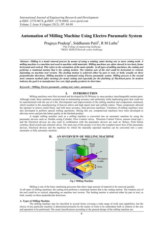
- 1. International Journal of Engineering Research and Development e-ISSN: 2278-067X, p-ISSN: 2278-800X, www.ijerd.com Volume 2, Issue 9 (August 2012), PP. 04-09 Automation of Milling Machine Using Electro Pneumatic System Pragnya Pradeep1, Siddharam Patil2, R M Lathe3 1 Pda College of engineering Gulbarga 2 HKES- BOSCH Rexroth centre Gulbarga Abstract––Milling is a metal removal process by means of using a rotating cutter having one or more cutting teeth. A milling machine is a machine tool used to machine solid materials. Milling machines are often classed in two basic forms horizontal and vertical. This refers to the orientation of the main spindle. At all types of milling machines, the cutting tool performs a rotational motion that is the cutting motion. The rotation axis of the tool could be horizontal or vertical, depending on machine tool version. The feeding motion is achieved either by part or tool, or both; usually on three perpendicular directions. Milling machine is automated using Electro pneumatic system. Milling process is the second most common method (after turning) for metal cutting and especially for the finishing of Machined parts. In modern industry the goal is to manufacture low cost, high quality products in short time. Keywords––Milling, Electro pneumatic, cutting tool, cutter, automated. I. INTRODUCTION Milling machines were first invented and developed by Eli Whitney to mass produce interchangeable musket parts. Although crude, these machines assisted man in maintaining accuracy and uniformity while duplicating parts that could not be manufactured with the use of a file. Development and improvements of the milling machine and components continued, which resulted in the manufacturing of heavier arbors and high speed steel and carbide cutters. These components allowed the operator to remove metal faster, and with more accuracy, than previous machines. Variations of milling machines were also developed to perform special milling operations. During this era, computerized machines have been developed to alleviate errors and provide better quality in the finished product. A simple milling machine such as a milling machine is converted into an automatic machine by using the pneumatic devices such as: Double acting Cylinder, Flow Control valves, Direction Control Valves, sensors (reed type ) and the Electrical devices are also used in combination with the pneumatic devices are such as: Relays, Push button switches, Reed switch and solenoid valves. The main aim of this project is to have the complete know how of the pneumatic devices, Electrical devices and the machines by which the manually operated machine can be converted into a semi- automatic or fully automatic machine. II. AN OVERVIEW OF MILLING MACHINE Fig.1 Milling Machine Milling is one of the basic machining processes that allow large amount of material to be removed quickly. At all types of milling machines, the cutting tool performs a rotational motion that is the cutting motion. The rotation axis of the tool could be or vertical, depending on machine tool version. The feeding motion is achieved either by part or tool, or both, usually on three perpendicular directions. A. Types of Milling Machine The milling machine may be classified in several forms covering a wide range of work and capabilities, but the choice of any particular machine is determined primarily by the nature of work to be undertaken both in relation to the size and operation to be performed. The usual classifications according to the general design of the milling machine are: 4
- 2. Automation of Milling Machine Using Electro Pneumatic System 1. Horizontal milling machine (a) Hand milling machine. (b) Plain milling machine. (c) Universal milling machine. (d) Vertical milling machine. 2. Manufacturing of fixed bed. (a) Simplex milling machine. (b) Duplex milling machine. (c) Triplex milling machine. 3. Planer type. 4. Special type. (a) Rotary table milling machine. (b) Drum milling machine. (c) Planetary milling machine. B. Parts of Vertical Milling Machine Base: The base of the machine is gray iron casting accurately machined. It carries the column at its one end. Column: The column is the main supporting frame mounted vertically on the base. The column is box shaped, heavily ribbed inside and houses all the driving mechanism for the spindle and table feed. Knee: The knee is a rigid grey iron casting that slides up and down on the vertical ways of the column face.Table: The table rests on ways on the saddle and travels longitudinally. The top of the table is accurately finished and T-slots are provided for clamping the work and other fixture on it. Spindle: The spindle of the machine is located in the upper part of the column and receives power from the motor through belts, gears, clutches and transmits it to the cutter. III. GENERAL CONCEPTS ON DESIGN AND DEVELOPMENT OF PNEUMATIC SYSTEMS A. Development of Pneumatic System The solution to a control problem is worked out according to a system with documentation playing an important role in communicating the final result. The circuit diagrams are drawn using standard symbols and labeling. Comprehensive documentation is required including most of the following Function diagram Circuit diagram Description of the operation of the system Technical data of the components. Supplementary documentation comprising Parts list of all components in the system Maintenance and fault-finding information Spare parts list There are two primary methods for constructing circuit diagrams: The so-called intuitive methods The methodical design of a circuit diagram in accordance with prescribed rules and instructions. Fig. 2 Functional Diagram Whereas much experience and intuition is required in the first case and above all, a great deal of time where complicated circuits are concerned; designing circuit diagrams of the second category requires methodical working and a certain amount of basic theoretical knowledge. Regardless of which method is used in developing the circuit diagram, the aim is to end up with a properly functioning and reliably operating control. Whereas previously emphasis was placed on the least expensive hardware 5
- 3. Automation of Milling Machine Using Electro Pneumatic System solution, more importance is now attached to operational reliability and ease of maintenance by a clear layout and documentation5. This inevitably leads to increased usage of methodical design processes. In such cases, the control is always constructed in accordance with the given procedure and is less dependent upon personal influences from the designer. In many cases, however, more components will be required for the methodical solution than in a circuit devised by the intuitive method. This additional material requirement will usually be rapidly compensated for by time-saving at the project stage and also later in terms of maintenance. Generally, it must be ensured that the time spent in project design and particularly in simplifying the circuit, is in reasonable proportion to the overall effort. Regardless of which method and which technique is used to produce a circuit diagram, the basic requirements are sound fundamental knowledge of the devices concerned and knowledge of the switching characteristics of the components used. In majority of the pneumatic applications more than one cylinder is used. The movement of these cylinders is coordinated as per the required sequence. The activation of the limit switches of different cylinders will provide set or reset signal to the final control valves for further controlling the movement of various cylinders. The limit switches have to be arranged in the proper location with the help of motion diagram. In order to develop control circuitry for multi cylinder applications, it is necessary to draw the motion diagram to understand the sequence of actuation of various signal input switches-limit switches and sensors. Multi cylinder applications with three cylinders A, B and C:The status of the cylinder displacement and actuation of set and reset signals at double piloted directional control value is shown by functional diagram. IV. OPERATIONAL AND ANALYSIS A. Cost Analysis of Manual and Automated Production Machine The machine taken for comparison is a milling machine. Depending upon the size of the machine the cost varies. Taking a minimum size of the machine the analysis is done.For manually operated milling machine the cost of minimum operated milling machine the cost of minimum size machine is approximately around80000/-. For automatically operated milling machine the cost of minimum size machine (after conversion) is approximately around 200000/-. Production time: Let us consider a milling machine which is used for milling a 5cm length in a mild steel piece. Manually operated milling: The time needed for machining manually operated milling machine is about 2mins. The total time needed including the loading and unloading is about 2 minutes. Therefore in 1 hour 30 jobs are made. There is one day (5 hours) 150 work pieces are completed. (Total machining time taken in a day is 5 hour). B Automated Milling The time needed for machining work piece on an automated milling machine is about 1 minute. In one hour 60 work piece are produced. Therefore in one day (5 hours) 300 work pieces are completed. To know the productivity of both the machines it can be understood from the graph. Fig. 3 Graph Showing Productivity Of Two Machines (Milling) AUTOMATED M/C MANUAL OPERATED M/C 1 HOURS-60 UNITS 1 HOURS-30 UNITS 5 HOURS-300 UNITS 5 HOURS-150 UNITS As seen from the graph the rate of production is very high in case of automated milling machine as compared with the manually operated machine. Hence, the productivity is high on the automatic machine. Break Even Analysis: In decision making breakeven analysis assumes an important place it helps its decision maker in the choice of the optimal price, cost and output levels of each products. Whatever may be objective of the firm profit maximization is the basic objective. The firm is interested in finding out the sales volume which will bring it to the maximum profit or for that matter the minimum loss. It is therefore interested in preparing chart to find out the areas of profit and loss in its operational process. The chart is called “Breakeven chart”. 6
- 4. Automation of Milling Machine Using Electro Pneumatic System Fig. 4 Break Even Chart The BEP is defined as that level of output where total revenue is equal to total cost. The point is a point of no profit, no loss. This point shows where loss stops and the profit starts. Increase in the sales beyond this point would result in profit. Decrease in sales below this point a result in loss of course the firm is interested in operating beyond the breakeven point (BEP). The firm will be most happy once it crosses. The BEP the firm incurs two types of cost 1. Fixed cost 2. Variable cost. The rental of a machine, building furniture etc is fixed cost. Cost of labor, raw material, fuel, etc are variable cost. A break even chart is a graphical representation of the relationship between the cost and revenue at a given time. It is a graphic device employed to determine the breakdown point (BEP) and profit potential under varying conditions of outputs and costs. While preparing break even chart we will assume that the firm incurs some fixed cost and some variable cost. This will give us the total cost function which may be either linear or non-linear. If the average variable cost is assumed to be constant over the range of output the cost function would be as shown in figure. Cost, variable cost and rate of production A business can work out how what volume of sales it needs to achieve to covers it costs. This is known as the breakeven point. The key to break even is to work out the contribution made from the sale of each unit. The amount of money each unit sold contributes to pay for the fixed and indirect cost of the business14. Manually operated machine (milling): Fixed Cost of machine (FC) : Rs. 80,000/- Variable Cost (VC) : Rs. 200,000/- Rate of production : 54750 units / year Sales (considering the : Rs. 273750/- Year Cost of machining Rs 5 per unit) (Machining time is taken 5 Hours per day) Scale: X AXIS 1CM=10000 Y AXIS 1CM=40000 Fig. 5 Manual Operated Machines’ Bep 7
- 5. Automation of Milling Machine Using Electro Pneumatic System Scale: X AXIS 1CM=4000 Y AXIS 1CM=10000 Fig. 6 Automated Machine’s BEP Automated machine milling: Fixed Cost of machine (FC) : Rs. 80,000/- Variable Cost (VC) : Rs.200,000/- Rate of production : Rs.109,500 units / year Sales (considering the : Rs. 547,500/- Cost of machining is Rs 5/- per unit) (Machining time is taken 5 Hours per day) From the BEP we can conclude that even though the initial investment is high but the returns of the investment is very quick as compared to the manual operated machines and also the profits are more in case of the automated machines when compared with the manual operated machine with in the same period of time. From the BEP chart of both the machines we come to a conclusion that why the automated machines are the first choice. Conventional Machine (Milling): 150 units are produced in one day, No. of days required to produce 29000 units (From the BEP of conventional machine BEP chart) Approximately 193 days are required. Automated Machines (Milling): 300 units are produced in One day, No. of days required to produce approximately 128000 units. (From the BEP of Automated machine BEP chart) Approximately 427 days are required. From the statistics, it shows that even though the initial investment is high, but the BEP would be reached approximately 427 days. In case of conventional machine the initial investment is low as compared to the automated machine, but to obtain the breakeven point it takes more number of days approximately 193 days and the profit is less. If there is a need of a production machine (Milling) for mass production, opting to a automated machine is must or else the existing conventional machines can be converted into automated machines, so the goal can be achieved i.e. Less time more profit. Hence it can be concluded that automated machines are better than the manual operated machines both in productivity and accuracy areas. V. CONCLUSION The manual controlled machine is converted into automatic machine by which maximum operating time will be saved. Thus the output will be more. The human intervention is minimized. As far as this project is concerned the machine is not fully automatic. It may be called as semi automatic because the loading of the sheet metal is done manually. But this machine can be made fully automatic by using more number of cylinders by which the machine is loaded automatically. So that the machine may run for longer time and unloaded without stopping the machine. Thus there will be a increase in the output. The number of workers is also minimized by which number of machines can be handled by a single operator. To conclude, this project is made keeping in mind that any manually operated machine can be converted to automatic machines by using these devices. For these purpose one should have the full knowhow of the devices which are being used. By doing so the existing old machines can be modified and made automatic by which the initial cost, to procure new automatic machines may be minimized. Thus there is a lot of scope in this area (automation). Further in this project the wiring is very much complicated, if any troubleshoot occurs then the fault cannot be easily found, for this the interface with the PLC can be used, by which the wiring is minimized and the fault can be easily detected without waste of time. Hence there is still wide scope in the automation area where lots of improvement can be made with the help of the latest technology. 8
- 6. Automation of Milling Machine Using Electro Pneumatic System REFERENCES [1]. Phillip F. Ostwald, Jairo Munoz, Manufacturing Processes and systems 9 th Ed., Wiley-India, 2008 [2]. S. R. Majumdar, Pneumatic Systems , Tata McGraw-Hill , 1996 [3]. W. Bolton,Mechatronics,4 Ed.,Pearson Prentice hall, 2008 [4]. Bosch-Rexroth, Manuals of Pneumatics. [5]. P. Croser, F.Ebel, Pneumatics, Festo, 10, 2002 [6]. Robotics and Automation by R.K Rajput [7]. www.omega.com , air-preparation [8]. www.wikipedia , chapter7, aircompressor-airfilters-lubricator [9]. www.en.wikipedia,relay [10]. www.britannica.com,automation,advantages&disadvantages [11]. www.jrank.org,pages,677,automation&application [12]. www.netviewforz,os,automation,guide,objectives [13]. www.enwikipedia,ladderdiargam [14]. www.enwikipedia,breakeven [15]. www.answer.com,industrialautomation,scope 9