Configuring a cisco router as a frame relay switch
•Descargar como DOCX, PDF•
0 recomendaciones•1,252 vistas

How to configure a cisco router as a frame relay switch?

Recomendados
Recomendados
Más contenido relacionado
Más de IT Tech
Más de IT Tech (20)
Último
Último (20)
Configuring a cisco router as a frame relay switch
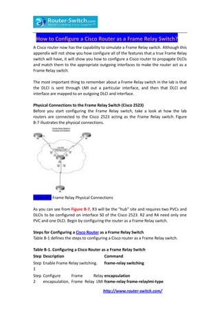
- 1. How to Configure a Cisco Router as a Frame Relay Switch? A Cisco router now has the capability to simulate a Frame Relay switch. Although this appendix will not show you how configure all of the features that a true Frame Relay switch will have, it will show you how to configure a Cisco router to propagate DLCIs and match them to the appropriate outgoing interfaces to make the router act as a Frame Relay switch. The most important thing to remember about a Frame Relay switch in the lab is that the DLCI is sent through LMI out a particular interface, and then that DLCI and interface are mapped to an outgoing DLCI and interface. Physical Connections to the Frame Relay Switch (Cisco 2523) Before you start configuring the Frame Relay switch, take a look at how the lab routers are connected to the Cisco 2523 acting as the Frame Relay switch. Figure B-7 illustrates the physical connections. Figure B-7 Frame Relay Physical Connections As you can see from Figure B-7, R3 will be the "hub" site and requires two PVCs and DLCIs to be configured on interface S0 of the Cisco 2523. R2 and R4 need only one PVC and one DLCI. Begin by configuring the router as a Frame Relay switch. Steps for Configuring a Cisco Router as a Frame Relay Switch Table B-1 defines the steps to configuring a Cisco router as a Frame Relay switch. Table B-1. Configuring a Cisco Router as a Frame Relay Switch Step Description Command Step Enable Frame Relay switching. frame-relay switching 1 Step Configure Frame Relay encapsulation 2 encapsulation, Frame Relay LMI frame-relay frame-relaylmi-type http://www.router-switch.com/
- 2. Step Description Command type, Frame Relay DCE interface ansi frame-relay intf-type dce clock rate mode, and clock rate on 64000 individual interfaces. Step Configure DLCI to interface frame-relay 3 mappings on individual route {local-dlci} interface {outgoing interfaces. interface and number} {outgoing-dlci} The first thing is to connect to the Cisco 2523's console port. There is no configuration on the router at this point. You should be in setup mode or at the Router> prompt. If you are in setup mode, just exit this mode (Ctrl-c). When you are into the router, give it a host name of Frame-Switch. Router>en Router#config t Enter configuration commands, one per line. End with CNTL/Z. Router(config)#hostname Frame-Switch Do not worry about passwords and Telnet connectivity. This router will be a standalone Frame Relay switch. If you need to access it, you will connect to the console port. Begin with the first step documented in Table B-1, and enable Frame Relay switching on the router. Example B-1 illustrates this configuration step. Example B-1. Enable Frame Relay Switching Frame-Switch(config)#frame-relay switching Frame-Switch(config)# After the Frame Relay switching process has been started, configure the individual interfaces for the Frame Relay switch. This includes changing the encapsulation type to frame-relay and changing the LMI type to ANSI. Because all interfaces on the Frame Relay switch are DCEs (refer to the Figure B-7), they will need to be changed to the Frame Relay type DCE and must have the clock rate command issued as well. Example B-2 demonstrates these commands for interface Serial0. Example B-2. Frame-Relay Commands for Serial0 Frame-Switch(config)#int serial0 Frame-Switch(config-if)#encapsulation frame-relay Frame-Switch(config-if)#frame-relay lmi-type ansi Frame-Switch(config-if)#frame-relay intf-type dce http://www.router-switch.com/
- 3. Frame-Switch(config-if)#clock rate 64000 Now that all the Frame Relay commands have been set, you need to map the local DLCI of this interface to the outgoing DLCI and port. Because the Serial0 interface has two PVCs, it needs two mappings. Example B-3 shows the commands. Example B-3. DLCI-to-Interface Mappings for Serial0 Frame-Switch(config-if)#frame-relay route 100 interface serial 2 101 Frame-Switch(config-if)#frame-relay route 200 interface serial 1 201 Frame-Switch(config-if)#no shutdown From Figure B-7, you know that Serial 0 has two PVCs, one to R2 and one to R4. The first highlighted portion of lines 1 and 2 in Example B-3 point out the local DLCI that will be advertised out Serial 0. Therefore, R3 will see DLCI 100 and DLCI 200 because R3 is connected to the Frame Relay switch on Serial0. The second portion of highlighting in lines 1 and 2 marks the outgoing interface to which each DLCI is mapped. Therefore, anything coming from R3 on DLCI 100 will be sent to Serial2, and anything coming from R3 on DLCI 200 will be sent to Serial1. The last portion of highlighting in lines 1 and 2 indicates the DLCI assigned to the outgoing port. So, anything coming from R3 on DLCI 100 will go out Serial2 to DLCI 101, and anything coming from R3 on DLCI 200 will go out Serial1 to DLCI 201. Don't forget to remove the interfaces from shutdown mode. The next thing you need to do is perform a similar mapping statement on interfaces Serial1 and Serial2, except that the numbers will be reversed. See Example B-4. Example B-4. Frame Relay Commands and DLCI-to-Interface Mappings for Serial1 Frame-Switch(config)#interface serial1 Frame-Switch(config-if)#encapsulation frame-relay Frame-Switch(config-if)#frame-relay lmi-type ansi Frame-Switch(config-if)#frame-relay intf-type dce Frame-Switch(config-if)#clock rate 64000 Frame-Switch(config-if)#frame-relay route 201 interface serial 0 200 Frame-Switch(config-if)#no shutdown The highlighted portion of the configuration shows the local DLCI (201), the outgoing interface (Serial0), and the outgoing DLCI (200). Next, do the same for interface Serial2. See Example B-5. Example B-5. Frame-Relay Commands and DLCI-to-Interface Mappings on Serial2 http://www.router-switch.com/
- 4. Frame-Switch(config)#interface serial2 Frame-Switch(config-if)#encapsulation frame-relay Frame-Switch(config-if)#frame-relay lmi-type ansi Frame-Switch(config-if)#frame intf-type dce Frame-Switch(config-if)#clock rate 64000 Frame-Switch(config-if)#frame-relay route 101 interface serial 0 100 Frame-Switch(config-if)#no shut Frame-Switch(config-if)# The highlighted portion of the configuration shows the local DLCI (101), the outgoing interface (Serial0), and the outgoing DLCI (100). At this point, you have a functional Frame Relay switch. You will be able to verify the connections in Chapter 7, "Router Interface Configuration," but for now, take a look at the configuration and do a show frame-relay route to verify that the configuration matches the lab diagram. Example B-6 shows the running-config file. Notice where the commands are located in the configuration file. Example B-6. Output from show running-config Frame-Switch#show running-config Building configuration... Current configuration: ! version 11.2 no service password-encryption no service udp-small-servers no service tcp-small-servers ! hostname Frame-Switch ! ! frame-relay switching ! interface Serial0 noip address encapsulation frame-relay clockrate 64000 frame-relaylmi-type ansi frame-relayintf-type dce frame-relay route 100 interface serial2 101 frame-relay route 200 interface Serial1 201 ! http://www.router-switch.com/
- 5. interface Serial1 noip address encapsulation frame-relay clockrate 64000 frame-relaylmi-type ansi frame-relayintf-type dce frame-relay route 201 interface Serial0 200 ! interface Serial2 noip address encapsulation frame-relay clockrate 64000 frame-relaylmi-type ansi frame-relayintf-type dce frame-relay route 101 interface Serial0 100 ! interface Serial3 noip address shutdown ! interface Serial4 noip address shutdown ! interface Serial5 noip address shutdown ! interface Serial6 noip address shutdown ! interface Serial7 noip address shutdown ! interface Serial8 noip address shutdown ! interface Serial9 noip address shutdown http://www.router-switch.com/
- 6. ! interface TokenRing0 noip address shutdown ! interface BRI0 noip address shutdown ! noip classless ! ! line con 0 exec-timeout 0 0 line aux 0 linevty 0 4 login ! end Frame-Switch# The highlighted portions illustrate all the Frame Relay configuration tasks that you completed. Notice that none of the interfaces has IP addresses, nor do any of the interfaces need them. You are only mapping DLCIs to interfaces. This is a Layer 2 function, not a Layer 3 function, therefore, no IP address are needed. The show frame-relay route command is a useful command in determining that your configuration is correct. Example B-7 shows the output from this command. Example B-7. Output from show frame-relay route Command Frame-Switch#show frame-relay route Input Intf Input Dlci Output Intf Output Dlci Status Serial0 100 Serial2 101 inactive Serial0 200 Serial1 201 inactive Serial1 201 Serial0 200 inactive Serial2 101 Serial0 100 inactive Frame-Switch# From this output, you can see that the Input Dlci matches the correct interfaces from the lab diagram in Figure B-7. You also can see that Output Intf and Output Dlci match to the correct interfaces and DLCIs as well. From here, you can assume that everything is configured correctly. The status will be inactive until you configure the Frame Relay interfaces on R2, R3, and R4 and remove them from shutdown http://www.router-switch.com/
- 7. mode. More Related Cisco Network Tips: How to Configure Cisco Routers as Frame Relay Switch (FRS)? http://www.router-switch.com/