What classes of SMD components is this category used for?
•
0 recomendaciones•578 vistas

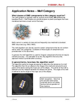
The melf category is typically used for surface mount Melfs (Metal Electrode Leadless Face ). Melf Diodes are cylindrical glass or plastic packages that have metallized terminals at each end of the body. Melfs

Recomendados
Más contenido relacionado
Más de Shenzhen Southern Machinery Sales And Service Co., Ltd
Más de Shenzhen Southern Machinery Sales And Service Co., Ltd (20)
What classes of SMD components is this category used for?
- 1. J. Herman 1 8/30/05 Application Notes – Melf Category What classes of SMD components is this category used for? The melf category is typically used for surface mount Melfs (Metal Electrode Leadless Face ). Melf Diodes are cylindrical glass or plastic packages that have metallized terminals at each end of the body. Melfs come in a variety of sizes and are frequently size-matched to standard SMD chip sizes (e.g. 0603, 0805). The melf algorithm can also be used for certain components that do not conform well to other UIC categories. Examples of these types of components are provided later in this document. In general, the melf algorithm is used for irregular components that do not require extreme accuracy. It is advisable to try the chip algorithm first since this approach tends to provide better accuracy. In general terms, how does the algorithm work? The algorithm performs image processing to determine the presence of a melf. The algorithm then fits an ellipse to the image of the melf and extracts the end points of the device along the major axis of the ellipse. The center of the melf is defined to be the midpoint between the ellipse end points. The angle of the melf is defined to be the angle of the major axis of the ellipse. Melf recognition. Note that this process takes place internally and is not visible during normal operation of the machine. 51030001, Rev C Melf centering, Standard Accuracy
- 2. J. Herman 2 8/30/05 Does the melf algorithm have a High Accuracy mode? How does it work? A new high accuracy melf algorithm was introduced in UPS+ 6.1.x. The algorithm was designed specifically for Melf devices because of the typical poor image quality associated with them. The rough position is found, then a bounding box of minimized area is placed around the found features. The position and rotation of the bounding box determines the reported position and rotation of the device. I’m running UPS+ 6.1 and I’ve created a new melf definition. Why isn’t there an Inspection Type selection on the Vision tab? The accuracy mode is normally controlled through the Inspection Type field of the component definition (Vision tab). In UPS+ 6.1.x, this field is not exposed when you create a new melf. The Inspection Type field for melfs will be included in the component definition as of UPS+ 6.2 (See below). In UPS+ 6.1, use the following workaround to turn on high-accuracy melf processing: • Create a new chip definition (the Inspection Type is always exposed for a new chip). • From the Vision tab of the component definition, change the Centering Type to melf and set the Inspection Type to High Accuracy. UPS+ 6.2 Users: Here is a machine image of a melf being centered in High Accuracy mode. At vision diagnostic level 5, the graphics display for high accuracy melf processing shows outlines as opposed to the green thresholding displayed with standard accuracy. No workaround is required in UPS+ 6.2: To run with High accuracy, create a new melf definition and change the Inspection Type to High Accuracy in the Vision tab of the component definition. New melf Vision tab for UPS+ 6.2 Melf centering, High Accuracy
- 3. J. Herman 3 8/30/05 Should I choose High Speed or High Accuracy? Here are the advantages (+) and disadvantages (-) of the Inspection Type settings: High Speed + Faster vision processing – Looser dimensional tolerances + Dimensional tolerances are fixed High Accuracy + Improved accuracy, robustness – Slight degradation in vision processing speed – Dimensional tolerances are programmable in UPS+ 6.2 In typical applications, melfs are not the dominant component on the circuit board. In this type of scenario, High Accuracy is a good choice since it provides a more accurate correction and supports programmable tolerances. If speed is a concern and the image quality is good (high contrast, lack of background noise), High Speed can be chosen. Note: High Speed and High Accuracy inspection types should not be confused with the Accuracy selection in the Heads tab of the component definition. This selection refers to the speed at which the machine runs when placing the component. How dimensionally tolerant is the algorithm? The dimensional tolerance of the melf algorithm depends on the Inspection Type chosen in the Vision tab: High Speed • The length tolerance is set at ±35% of the programmed length of the melf. • There is no width tolerance check. High Accuracy • UPS+ 6.1: The tolerance is set exactly as in the High Speed case. • UPS+ 6.2: The length and width tolerances are taken from the tolerance fields of the component definition. High Accuracy melf – dimensional tolerance in UPS+ 6.2 By default, when you create a melf definition, default dimensional tolerances are set according to the following rules: Let D = The programmed length or width of the melf Small melf case: D < 0.015” (rare) The tolerance for this dimension is set to ±20% Larger melfs: D > 0.015” The tolerance is at most 35% and is capped at ±0.015”.
- 4. J. Herman 4 8/30/05 Examples: Melf Type Length (0.001“) Width (0.001“) Length Tolerance (%) Width Tolerance (%) 0201 20 10 ±35% ±7-mils ±20% (W < 15-mils) 0402 40 20 ±35% ±14-mils ±35% ±7-mils 1206 120 60 12.5% ±15-mils* 25% ±15-mils* * Default tolerance % driven by ±0.015” cap. When you program a melf using the High Accuracy Inspection Type, the database dimensional tolerances are used for size checking. The melf dimensional tolerances can be changed in the same manner as chips. To access the tolerances, select the Next… button on the Body tab of the melf definition: The tolerances can be changed in the range of 1 – 100%. NOTE: Care should be taken in programming large tolerances as this can lead to the possibility of a wrong-sized part being placed on the board. How small a melf can the machine handle? The answer to this question depends on the camera used to center the melf. The vision system requires a minimum of 12 pixels x 6 pixels to accurately center a leadless component. The table below lists several camera types and the minimum melf size supported based on the minimum pixel requirement. Camera Minimum Melf Length (12 pixels) Minimum Melf Width (6 pixels) Magellan 2.3 mil/pixel 0.028” 0.014” FlexJet 1.1 mil/pixel 0.014” 0.007” HSC 0.8 mil/pixel NFOV 0.010” 0.005”
- 5. J. Herman 5 8/30/05 What types of nozzles do I use for melfs? Melfs require nozzles that conform to their cylindrical shape. There are several melf nozzles available for each UIC head type. Contact your UIC Applications or Field Engineer for nozzle recommendations for specific components Are there other programming considerations with melf nozzles? Yes. Since melf nozzles are not axially symmetric, you must define the Body Length and Body Width to match the 0° shape of the nozzle. For example, the 0° shape of a melf nozzle tip is shaped to pick a melf with its long axis oriented along the x-axis of the machine. So in this case, you program the melf with a Body Length greater than the Body Width: In addition, it is important that you turn off APU for melf components. Since the melf nozzle is designed to conform to the shape of the device, APU is not needed. To turn off APU for components using melf nozzles, uncheck the APU checkbox in the Heads tab of the component definition: Example of a melf nozzle: FlexJet 1340 nozzle.
- 6. J. Herman 6 8/30/05 Turn off APU for all heads picking components using a melf nozzle. Do I have to teach melf tape feeders? We recommend using melf nozzles to pick melf components. Since the nozzle is shaped to fit the particular melf being picked, teaching the feeder (or at least verifying the pick position) is a good idea. Can the vision system tell me how large the melf is? For UPS+ 6.1 and higher, the answer is yes. Follow this general procedure: 1. Pick up a melf in Enhanced Component Setup. The programmed size should be reasonably close. 2. Inspect the melf. If the melf happens to pass inspection or fails inspection due to the size being out of tolerance, the Retrieve Observed button is enabled in the ECS options section. 3. Select the Retrieve Observed button. The perceived size of the melf from the vision system is returned to the component definition.
- 7. J. Herman 7 8/30/05 The melf algorithm seems very flexible. Are there any risks associated with it? There are some risks associated with the melf algorithm. In standard accuracy mode, the melf algorithm can be extremely forgiving and can be used to locate many devices that otherwise would not be located using the chip algorithm. This flexibility can also lead to poor centering performance with images that contain background noise (e.g. overhanging reflective nozzles, contaminated nozzles). For both standard and high accuracy melf processing, the algorithms are intended to locate components anywhere in the field of view where the spindle is completely obscured. Overhanging reflective nozzles such as those found on HSC machines will affect the accuracy of the algorithm. If you are using the melf algorithm to center melf devices, the specially designed nozzle will not be visible in the image. The overhanging nozzle risk is more of a factor in scenarios where the melf algorithm is used on devices that are not actually melfs. In both modes, depending on the component and nozzle sizes, there is the possibility of finding an empty nozzle. The risk of this is highest in Standard Accuracy mode where the inspection tolerances are loose. What are the typical vision failure modes for melf centering? “Major/minor dimension out of range” One of the most prevalent failure modes for melf inspection is “major/minor dimension out of range”. In some cases, the melf is simply dimensionally misprogrammed. If this is the case and the failure is repeatable, use the Retrieve Observed option in Enhanced Component Setup to capture the perceived melf size from the vision system. Note that the perceived size depends on several factors including light type and intensity, component geometry (rounded edges/corners), and metallization. In other cases, the dimensional failure can be caused by contamination on the nozzle. In the image below, a component is being centered using the high accuracy melf algorithm. Contamination on the nozzle is causing the algorithm to fail with a dimensional error. Contamination Things to try… • Clean the nozzle • Do not use excessive light levels • For non-contamination scenarios, use ECS Retrieve Observed to ensure that the programmed size is close to the perceived size
- 8. J. Herman 8 8/30/05 Dirty nozzle skew Standard accuracy melf processing is susceptible to skewed centering as a result of nozzle contamination. Consider the following image: Nozzle being found as a melf As mentioned earlier, one of the risks of the melf algorithm is recognizing a bare nozzle as a component. Keep in mind that the risk of a nozzle being recognized as a component depends on the programmed size of the component compared to the size of the nozzle, and the tolerance of the algorithm. The standard accuracy melf algorithm is particularly susceptible to this error due to its fixed and loose dimensional tolerances. The high accuracy melf algorithm is also susceptible as the image below illustrates (the red box indicates the programmed size of the component): The good news is that in UPS+ 6.2, dimensional tolerances are programmable for the high accuracy melf algorithm. Contamination Contamination on the shoulder of the nozzle is leading to a skewed correction. Things to try… • Clean the nozzle • Do not run with excessively large search areas • Do not use excessive light levels • Consider using High Accuracy mode HSC nozzle being centered with the high accuracy melf algorithm. Things to try… • To help filter out empty nozzles being centered as a component, use the high accuracy mode. • Reduce your dimensional tolerances until the nozzle fails inspection.
- 9. J. Herman 9 8/30/05 What other types of components can be centered the melf algorithm? Our preliminary experience with the high accuracy melf algorithm has shown it to be an effective tool with components that do not fit nicely with other component categories. Examples below include a coil with irregular shaped leads and an LED with a non-rectangular outline. User Notes: Coil: FJ 2.6-mpp, melf centering type, High Accuracy LED: FJ 2.6-mpp, melf centering type, High Accuracy