SlideShare a Scribd company logo
1 of 15
Download to read offline
CONVENTIONAL POWDERED METAL COMPONENTS


ABSTRACT

Powder Metallurgy (PM) has advanced considerably during the last seventy years. This
paper describes the conventional press & sinter process used for manufacturing highly
sophisticated net-shape metal components. It highlights process advantages and the
effects derived from material or process choices. Those choices must be understood
when designing PM components since they significantly effect the physical and/or
mechanical properties of the finished component.


WHAT IS PM?

Powder Metallurgy or PM is a highly developed method of manufacturing precision
metal parts. Over the last seventy years, the technology has matured from making self-
lubricating bearings for autos to complex carrier gear sets in automobile transmissions
and high strength powder –forged connecting rods in engines. When we use the term
PM within the industry, it also refers to related technologies such as metal injection
molding, isostatic pressing and powder forging.

PM manufacturing technology consists of three steps; mixing elemental or alloy
powders, compacting those powders in a die at room temperature and then sintering or
heating the shape in a controlled atmosphere furnace to bond the particles together
metallurgically. Generally, scrap rates for the process are less than 3 per cent.

Because the process has so little waste and the part, is often finished when taken from
the furnace, the process is very cost effective when compared to manufacturing
processes that must contend with flash, machining chips, and sprues and gates. The
speed of the presses is such that simple or complex parts can be made to close
tolerances, often eliminating machining. Production runs range in number from a few
hundred to thousands of parts per hour. Conventional PM parts are limited to parts
which can be formed uniaxially.

 Frequently, the technology is used for material systems that are hard to machine such
as tungsten or molybdenum or hard to cast due to detrimental solidification behavior of
the material systems chosen.

The utility of the process can also be found by combining previously separate shapes
into a one-piece PM part, avoiding additional assembly or joining steps in the
component’s design. In some cases, PM parts can be joined by bonding or other
joining techniques to give greater utility to the designed component. Today’s presses


                                           1
enable parts to range between simple, single level shapes to complex, eight level
shapes.

The basic versatility of PM is demonstrated by the use of components in the automotive,
aerospace, business machine, electronics and appliance markets. Thousands of
different, reliable cost-saving designs now serve these industries. The average U. S.
full-size passenger car contains more than 16.4 kilograms (36 pounds) of PM parts.

PM’s flexibility is becoming more pronounced with the advent of its use as a forming
technique to manufacture components with very novel material combinations. The
designer can adjust the chemistry and other PM characteristics, such as density, to
provide a custom result, uniquely suited for the application. Materials can include
ceramics, nanophase materials, semi-metals and functionally gradient materials.


THE ADVANTAGES OF THE PM PROCESS

As we get more detailed in this discussion, it will become more apparent how the PM
process delivers its many advantages. Perhaps PM’s strongest benefit is its ability to
eliminate or minimize machining. Tolerances, which I will compare later, are the key
issue here. Like many component design processes, the earlier a competent PM parts
designer is brought into the design process, the more likely a design can be optimized
to meet the needs of the component’s function, which should be followed by form.

Following on the minimization of machining, and since the component is shaped in a
closed die, there is little or no trim or other process related scrap. Strict process control
and the reproducibility inherent in the process result in consistent quality and little
rejection due to off specification components.

These days, close dimensional tolerances, are essential to the reliability and
performance of an assembly. PM’s ability to control tolerances is one of the secrets to
its successful adoption in the conversion of many components from competing forming
technologies.

There is essentially no limit to the variety of alloy systems that can be used to produce a
shaped component. This gives the designer considerable latitude in matching function
and application requirements with a material system to meet those needs such as
strength, corrosion resistance or other particular metallurgical or mechanical properties.

PM parts have a surface finish of between 32 –48 microinches (Ra). Produced from a
die with surfaces of 20 –32 microinches.

PM parts can be enhanced using heat-treating, coining, burnishing or other secondary
operations that can result in property improvement.


                                              2
As we mentioned above, one of the first modern uses of PM components was in self-
lubricating bearings. By controlling the density and particle size, very specific pore
characteristics can be designed into an application. If the porosity is interconnected, the
component can be used in very fine, high temperature filter applications.

Complex shapes can be made easily and efficiently. The ingenuity of the designer and
the ability of the part to be ejected from the compaction die are the only limits to the
choices.

Most PM dies are made of high strength, durable alloys such as tungsten carbide or
high-speed steel, which permits high volumes of parts to be produced before wear of
the tooling becomes a consideration. Once a part is being produced in a “steady-state”
fashion on a set of tools, the results are consistent from part -to -part.

Since the dies and tooling are so durable, high volumes of parts can be economically
produced at high speeds, subject to the limits of the press capacity.

The largest market for PM components is the automotive sector. Nearly 70 % of all PM
parts are used in this industry. The applications are frequently found in the drive train
and transmission where the demands for performance and reliability are great. One
major application is connecting rods. Millions of rods have been produced over the last
twelve years, without a failure.

Following on that comment, it goes without saying that the most cost conscious of
buyers can be found in the auto industry. If PM weren’t economical, the auto industry
would use a different technology.

Most powder is produced from scrap metals and as such helps limit environmental
impact through recycling. The net shape characteristic of the component and the
limited use of energy for heating imply that a minimum amount of energy is used to
meet the needs of the application. Minimizing machining lowers the likelihood of water
pollution due to cutting fluids and oils.


THE BASIC PM PROCESS STEPS

As mentioned above, the three basic steps for PM manufacturing are mixing,
compacting and sintering.

PM powders can be produced by taking elemental, partially alloyed or prealloyed metal
powders and mixing them with lubricants such as graphite or waxes to produce a
homogeneous mixture of ingredients. Since the density and consistency of fill of the die
is important to maintain uniform part production, the importance of this step of the
process can not be minimized. The additives can also be introduced to aid
machinability, wear resistance or lubricity of the base alloy composition.


                                             3
. A controlled amount of mixed powder is automatically gravity-fed into a precision die
and is compacted. Usually this is done at room temperature at compaction pressures as
low as 138 MPA (10 tons per square inch) to as high as 827 MPa (60 tons per square
inch) depending on the density requirements of the part and powder being pressed.
Normally the compaction pressures are 345 to 690 MPa (25 – 50 tons per square inch).
The compacted or “green” part has the size and shape of the finished part when ejected
and has sufficient green strength to be handled and transported to the sintering furnace.

In the sintering step, the green compact is placed on a mesh belt, and slowly moves
through a controlled atmosphere furnace where the parts are heated to a temperature
below the melting point of the base metal, held at the sintering temperature and then
cooled. The sintering step transforms compacted mechanical bonds between the
powder particles into metallurgical bonds by a solid state transformation process


PM MATERIALS

Metal Powders are precisely engineered materials that meet a wide range of
performance requirements. These engineered materials offer wide latitude to develop
materials with properties tailored to the application through metal alloying. These
engineering properties are affected by several factors that include material type, powder
fabrication process and the component manufacturing process.

Basically four methods are used to produce powder: atomization, chemical, thermal and
electrolytic. Choosing a method is determined by the economics, raw material and the
desired particle shape, size and size distribution. The particle shape, size and size
distribution profoundly affects the way the powder behaves during die filling, compaction
and sintering. The range of shapes can be irregular, flake, dendritic and sponge
(porous). Figure I displays the morphology of these shapes for various powders.


                                            4
(Typical metal powder particle shapes: atomized Cu, water atomized Fe, sponge Fe, electrolytic Cu - upper left to lower right)
                                                            Figure I

There are three types of powders. The first type is an admixed powder, so called
because elemental powders such as copper, nickel and graphite are added to a base
element powder such as iron or copper. These powders are used in circumstances
where high purity is essential to material properties. Use of these elemental powders
gives a manufacturer a lot of choice in tailoring the mixture to design requirements by
mixing with other powders before pressing and sintering. However, elemental powders
exhibit lower yield strength than prealloyed powders, allowing them to deform more
readily during compaction, thereby improving density and green strength. They do not
however, display the same degree of homogeneity of prealloyed powder during normal
sintering.

Partially alloyed powder is composed of two or more elements where the alloying
additives are diffusion bonded to the base powder during the powder manufacturing
process. This is done to enhance the compressibility of the base powder. These
powders tend to be non-homogeneous, and therefore have diverse microstructures, but
controllable phases. The chemistry can be closely controlled which enhances
dimensional control. These materials also tend to have excellent fracture toughness.

The last category, prealloyed powder, is typically atomized from alloyed furnace melts.
Each particle has the same nominal composition as the next. Prealloyed powders yield
homogeneous phase constituents throughout the microstructure. Prealloying is used to
achieve alloys that are difficult to achieve by mixing elemental powders, such as
stainless steel.

In some cases, there are other additives in the powder mixtures, added for purposes
such as lubrication, organic powders that vaporize during sintering to produce specific
microporosity for filter applications and organic binders that allow the feedstock to be
molded like the materials used in plastic injection molding.

In addition to the metallurgical and chemical properties derived from the materials, there
are a number of other properties that are important to a PM material. They include
particle size distribution, particle shape, flow rate, bulk density, compressibility, green
strength and the spring-back characteristics of the powder. Each of these properties
has an effect on the workability, for lack of a better word, and the final characteristics
and performance of a component.


                                                                 5
THE PRESSING CYCLE

The adjacent figure (FIGURE II) offers a schematic analysis of the compacting process
in a traditional PM press.


                                          Figure II

The pressing cycle begins with the die receiving a charge of the mixed powder,
delivered to the cavity by a feeder shoe that slides across the top of the tool set. The
volume fed into the die is controlled by the relative position of the lower punch in the die.
Once filled, the feed shoe withdraws and the next part of the cycle occurs as the upper
and lower punches compress the powder into the die shape. When this step is
completed, the upper punch withdraws and simultaneously, the lower punch rises,
ejecting the pressed compact, and once clear, the feeder shoe pushes the compact
away from the die cavity and another cycle of powder charging begins.


                                              6
Powder characteristics have considerable impact on the final outcome of this portion of
the process, particle shape effects bulk flow rate, bulk flow effects final density and the
amount of powder delivered to the tooling, and compressibility effects the final density of
the component. Consistent delivery of a specific amount of powder and exact
repeatability of the relative motion of the punches in the die set is essential to consistent
component properties.

The behavior of powder during compaction significantly affects the properties. During
the early stage of compaction, the particles reorient to a denser particle packing level
with less microporosity, thus increasing surface contact between particles. As the
compaction increases, plastic deformation of the particles occurs before the final stage
of compaction when cold welding and interlocking of the particles occurs, imparting
sufficient strength to the green part for ejection and further handling. The goal during
the compaction cycle is to impart uniform density throughout. The mechanics of
compaction are largely governed by friction between the die and the powder and
between the powder particles. Hence, tooling is a critical element in the fabrication
process. The suitability of a component for PM manufacture depends essentially on the
issues of whether suitable, compaction tooling can be designed and built. There is no
known theoretical limit to the size of a PM component. The final density and the
available press size are the practical limits. As a practical guide, the projected area
(area perpendicular to the pressing direction) usually is between 4 and 16,000 mm2
(.006 and 25 square inches), with length between 0.8 to 150 mm (.03 and 6 inches),
although 75 mm (3 inches) is the practical maximum. There are parts weighing 11.4
kilograms (25 pounds) in production today.

Figure III identifies the elements of a tool set which usually consists of a die body or
mold, upper and lower punches and in some cases, one or more core rods.


                                         Figure III


                                              7
The initial cost of PM tooling depends upon the level of sophistication of the component
to be produced. The tooling must be robust enough to last from several hundred
thousand cycles to over a million cycles without wear and damage. The tools are
subjected to high compaction pressures, often as high as 690 MPa (50 tsi) for some
steel components, as well as the abrasive characteristics of the powders.

The die set must be able to withstand radial pressure during compaction and hold
tolerance in the horizontal direction of the component. The die set also tends to
experience the most wear, especially along the walls due to the ejection motion of the
green part. Its design must consider distribution of the gravity fed powder and the part
size. Wider parts are possible if perpendicular dimensions are reduced so that the
maximum projected area is not exceeded.

Punches transmit pressure to the powder in the die cavity. Punches must be able to
resist expanding under repeated compaction cycles. The punches must possess high
compressive yield strength, toughness and fatigue strength.

Core rods are used to shape through holes in the component. Like the dies, core rods
should be made from cemented carbides. Cemented carbides impart high hardness
and superior wear resistance to tool sets. During the compacting phase, core rods are
subjected alternately to high compressive and high tensile stresses, especially if they
are thin or have complicated profiles.

PM components are typically classified into one of four classes according to their
complexity. The complexity refers to the motion necessary to form a component. Class
one refers to simple one level parts with a low length/diameter ratio. Class two
components have a higher l/d ratio and require that the punches more from both
directions to make sure that density is as uniform as possible throughout the
component. Class three components are two level parts that must be pressed from two
directions and Class four components are multi-level components that require pressing
from two directions. Complex components formed using multiple punches and core
rods can have five or more levels depending upon the complexity of the press. Today’s
presses enable parts to range between simple, single level shapes to complex, eight
level shapes.


SINTERING

The traditional furnace found in the PM industry is a mesh belt furnace with three
operating zones; a pre-heat or de-lube zone, a hot zone and a cooling zone.

The furnaces usually operate between 1120 to 1150 degrees centigrade (2050 and
2100 degree F) for ferrous parts and 790 to 845 degrees centigrade (1450- 1550
degrees F.) for bronze materials. The trip through the furnace for a single part takes
about 2 to 3 hours, depending upon the size of the part. Some components are


                                            8
sintered at a temperature 300 degrees Fahrenheit higher, a process called high
temperature sintering, an effort made to enhance mechanical properties. Another
variation on the process is called sinter-hardening, accomplished by using a controlled
cooling rate in the cooling section of the belt furnace, transforming the steel matrix of a
ferrous part to martensite, thereby eliminating the need for a secondary hardening step.


SECONDARY OPERATIONS

With the exception of repressing, impregnation and infiltration, a sintered PM
component can be finished or treated, if necessary, just like any other metal component.
PM components can be plated or coated for corrosion resistance and can also accept a
black oxide coating to act as a paint base. Deburring can be performed to relieve sharp
edges and ferrous parts can be burnished to control size and surface finish. Ferrous
PM components can be successfully welded using just about any welding technique,
given allowances for density, alloy composition, proper joint design and elimination of
contaminants. Furnace brazing is often used to join other materials.

PM components can be heat treated to improve strength and hardness and can be
steam treated to make the surface hard and more wear resistant and well as
contributing to improved corrosion resistance and the sealing of porosity.

Repressing or coining is performed on PM components to densify or modify the surface
shape and provide stricter dimensional control. This can also be achieved by sizing a
component.

Oil impregnation, used on PM self-lubricating bearing components since the late 1920’s,
involves either soaking or vacuum processing. The components can absorb between
12 and 30 % oil by volume. Resin impregnation is performed on PM components to
improve machinability or to prepare the surface for plating by making the surface liquid
or gas tight and the surface “pore free”.

Infiltration is a secondary process step used to either improve strength or seal parts and
make them gas or liquid tight. Optional, like resin impregnation, it can also be used to
enhance machinability and improve ductility and prepare parts for plating. It is not used
to prevent PM defects.


DESIGN DETAILS

As mentioned above, holes are produced by core rods, which can be round, D-shaped,
or include keyways or splines. They can also be used to provide lightening holes to
reduce the projected pressing area.


                                             9
Wall thickness is always a careful consideration. Since die fill is important to get
uniform density, long thin walls are a challenge and are seldom less than 1.52 mm (.060
inches) or have a length to thickness ratio exceeding 8 to 1. Thin walls result in fragile
tools.

Flat components pose a distortion problem during sintering. As such, flat parts are not
the best application for PM. Often, repressing is required to improve flatness.

Most PM components do not require draft on the sides of parts.

Generally, fillet radii are most desirable. Tooling with generous fillets tends to last
longer and result in higher component manufacturing speeds and greater tool integrity.

Chamfer is a feature employed to prevent burring on part edges.

Countersinks are formed by a punch around a hole to accommodate a screw or a bolt
head.

Flanges are produced by machining a shelf or step into the die.

Bosses are forming cavities often located in punch tools. There are a few rules about
depth of cavity exceeding part heights, generally restricted to less than 15%.

A hub feature on a part should include a generous radius between the hub and the
flange section and to maximize the space between hub outside diameter and gear or
sprocket root diameters.

Studs with drafted sides can be made like bosses, however, always consider the
fragility of the green compact prior to sintering.

Grooves can be pressed into either end of a part from projections on the punch face.
Deep, narrow slots require fragile tooling and should be avoided.

Undercuts on the horizontal plane (perpendicular to the pressing direction) cannot be
formed, except when machined as a secondary operation, as they inhibit part ejection.
If there is a juncture undercut, the alternative is to press a semicircular groove at the
horizontal portion of the juncture.


TOLERANCES

In general, the dimensional tolerances that can be held in the PM process compare
favorably with other metal forming processes. The tighter the tolerances, the greater
the cost. Economically, tolerances no closer than necessary should be specified. The
limits on tolerances depend on orientation of the dimension to the pressing direction,


                                            10
size, component complexity type of material, process variations and secondary
operations.

Radial dimensions are controlled by the dimension of the tools, while the axial
dimensions are controlled by the motions of the press and the accuracy of the fill, thus
requiring more latitude. Dimensional tolerances are proportional to the size of the part
in the radial direction. Complex parts require increased tool complexity and thus more
relative tool movement and the press movements contribute to component tolerances.

Run-out tolerances on components with a hole, such as a gear, is affected not only by
die accuracy, but also by the required running clearances of the tool set and the
condition of the compaction press.

Flatness is a function of component thickness and surface area. Thinner parts will tend
to distort during sintering and shapes with unequal thickness may have density
variations which will make flatness difficult to maintain.

Powder formulation can affect components with variations in density, chemistry and
reaction to the furnace atmosphere during sintering.

Tool wear is an obvious source of variation in tolerancing components.

Coining or sizing can improve tolerances. The following table (I) offers typical
tolerances for a ferrous PM component measuring up to 100 mm (4 inches) in diameter
and 25 mm (1inch) thick.
                                        Table I
                          Pressed and Sintered Tolerances
                                    Practical                  Possible
                                mm            (in.)        mm              (in.)
Length (+/-)                   0.190        .0075         0.130            .005
Inside diameter (+/-)          0.100          .004        0.050            .002
Outside Diameter (+/-)         0.100          .004        0.050            .002
Concentricity                  0.150          .006        0.100            .004
Flatness on ends               0.130          .005        0.100            .004
Parallelism of ends            0.130          .005        0.100            .004


Engineering Properties
The first three properties of density, porosity and permeability are inter-related. Porosity
is the converse of density which is often expressed as relative density, the ratio of a
part’s density to that of its pore-free equivalent. The most common approach is to
express the density in grams per cubic centimeter. Porosity is present as a network of
interconnected pores that extend to the surface like a sponge or as a number of closed
holes within the part. In the first case, porosity is important to the function of the design.
In the latter case, less porosity is better. The porosity is a controllable function of the


                                              11
raw material and processing techniques. Permeability can be designed into a PM
component to vary between a highly restricted to open flow.

Like wrought metals, PM components and materials use ultimate tensile and yield
strength to indicate the strength of an alloy. This property is heavily dependent upon
density. Impact energy is also affected by density. In some PM material systems, such
as stainless steels, the yield strength may exceed the strength of wrought materials.

Ductility is relatively low in PM materials due to the presence of pores in the material.
This property can be improved by hot or cold repressing and resintering.

Hardness of PM parts cannot be directly compared using standard hardness testing
equipment scales. It is measured as apparent hardness, which takes into account the
combination of particle hardness and porosity. Standard testing equipment often
displaces particle or sees excessive compression of the surface.
Corrosion resistance is hampered by the porous nature of PM components, but
stainless steel parts have relatively good corrosion resistance. Other non-ferrous alloys
have corrosion resistance similar to wrought components.

Excellent surface finish is inherent is PM components. The overall smoothness and
surface reflectivity depends upon density, tool finish and any secondary operations.
Profilometer readings on PM components are taken with a chisel stylus to account for
pores of varying sizes. PM finishes compare well with wrought or cast components

Like conventional wrought steels, PM components are hardenable.

Table II is a comparative sample of PM properties with a wrought material (4340).
             C      NI       CU      Mn             CR        T.S.        Y.S         Elong   Hardness
                                                              MPa (ksi)   MPa (ksi)   %

4340 *       .4     1.65 –           .6 - .8        .7 - .9   1240        1160        17      39
@1000   F           2.00                                      (180)       (168)               HRC

FN – 0208    .6 -   1.0 –    0.0 -                            1340        1240        .5      42
(180 HT)
7.4 g/cm
        3    .9     3.0      2.5                              (195)       (180)               HRC


FC – 0205    .3 -            1.5 –                            690         620         .5      36
(-90HT)
7.0 g/ cm
         3   .6              3.9                              (100)       (90)                HRC
ss-316L      0-.3   10 -14           0-2            16 -18    280         140         18.5    20 HRB
6.6 g/cm3                                                     (41)        (20)
* Metals Handbook – 4340 tempered @ 1,000°F - ASM International, Volume 1, ninth
edition, p 426.


                                               12
ADDITIONAL PM “SHAPE” TECHNOLOGY

In addition to conventional “press and sinter” PM technology, there are a number of
allied metalforming techniques that offer design engineers options and choices when
designing components. Some of these techniques would be characterized as non-
conventional PM applications.

If a designer is trying to develop an application that has three axes of design freedom
and employs metal powders, the design choice for relatively small parts and large
volumes is metal injection molding. The process is analogous to plastic or ceramic
injection molding and can produce metal components with exceptional dimensional
tolerance capabilities, unique metallurgical properties and require no machining. In
general, parts are small, less than 500 grams, but this is changing with the introduction
of new binder materials and the deployment of larger presses and more efficient
furnaces for debinding and sintering. The part shown in Figure IV is an instrumental


                                        Figure IV

sensor control valve for chemical and oil flow control. It was made from a 50-50 nickel –
iron alloy that enables a magnetic flux to be applied through the body of the assembly.
It replaced a four-part assembly.

While we have not discussed the magnetic characteristics and capabilities of PM, this
component is an axial flux stator. This example, figure V, of PM’s capabilities replaced


                                            13
Figure V

a laminated electrical steel assembly and enables the magnetic flux to move in three
dimensions, not just two.

Another unique shape for our industry is this titanium softball bat outer shell (Figure VI).


                                         Figure VI

This application was formed using cold isostatic pressing and is an excellent example of
what can be achieved with a little ingenuity. The shell is subsequently hot isostatically
pressed. The only secondary operations are surface conditioning and cutting to length.
The shell has an ultimate tensile strength of 150,000 psi and 12 % elongation. Hot
isostatic pressing is becoming more prevalent with higher volume applications on the
near horizon due to faster cycling of HIP equipment. Very large, three thousand pound
near net shape compacts are possible using HIP. In addition, to their size, HIPing is


                                             14
being used with material systems such as titanium –aluminides. Again demonstrating
the ability of PM to enable cost effective fabrication of unusual alloy combinations.

Spray forming is a process used to produce semi-finished mill products in the form of
billets, tubes and sheet or plate. This is a sequential stage process consisting of liquid
metal atomization, and droplet consolidation to produce a near net shape. The products
typically have a close to fully dense and fine equiaxed grain structure. The mechanical
properties meet or exceed those of ingot processed alloys.

Metal matrix composites, the most popular being aluminum-silicon carbide particulate
reinforced materials, are frequently being used in aerospace, sporting goods products
and electronic thermal management component manufacture. The process employed is
usually cold isostatic pressing followed by hot extrusion or forging to full density.

The last PM forming technique I would like to discuss briefly is powder forging of metal
powder. Generally, the practice is to manufacture a “green” compact called a preform,
sinter it, and then restrike/forge the preform to the required final density. This process
results in a product with wrought properties.

FINAL COMMENTS

The real advantage of PM is to cost effectively produce large volume, highly toleranced,
metal components. The ongoing debate has always centered on properties, such as
strength and size. As you can see from the above comments, PM is rapidly overcoming
these modest objections as material selection and material characteristics are being
engineered to specific applications and requirements. Flexibility and knowledge of
process variables is the key for both the end-user and the component manufacturer.
Non-conventional PM applications are effectively dealing with size constraints and metal
injection molding can deal with any part geometry you can imagine.

We, as an industry, see challenging new horizons that only require a little inspiration,
ingenuity and persistence.


                                            15

More Related Content

What's hot

Improving Structural Integrity with Boron-Based Additives for 3D printed 420 ...
Improving Structural Integrity with Boron-Based Additives for 3D printed 420 ...Improving Structural Integrity with Boron-Based Additives for 3D printed 420 ...
Improving Structural Integrity with Boron-Based Additives for 3D printed 420 ...Dalton Stetsko
 
An Overview on Different Processing Parameters in Particulate Reinforced Meta...
An Overview on Different Processing Parameters in Particulate Reinforced Meta...An Overview on Different Processing Parameters in Particulate Reinforced Meta...
An Overview on Different Processing Parameters in Particulate Reinforced Meta...IJERA Editor
 
IRJET- Production of Powder Compact with the Help of Universal Testing Ma...
IRJET-  	  Production of Powder Compact with the Help of Universal Testing Ma...IRJET-  	  Production of Powder Compact with the Help of Universal Testing Ma...
IRJET- Production of Powder Compact with the Help of Universal Testing Ma...IRJET Journal
 
A04011 03 0112
A04011 03 0112A04011 03 0112
A04011 03 0112IJMER
 
IRJET- Mechanical and Tribological Characterisation of Sintered Iron and Alu...
IRJET-	 Mechanical and Tribological Characterisation of Sintered Iron and Alu...IRJET-	 Mechanical and Tribological Characterisation of Sintered Iron and Alu...
IRJET- Mechanical and Tribological Characterisation of Sintered Iron and Alu...IRJET Journal
 
Sheet Moulding Compounds
Sheet Moulding Compounds Sheet Moulding Compounds
Sheet Moulding Compounds ShravanPathak4
 
Powder metallurgy (2) (1)
Powder metallurgy (2) (1)Powder metallurgy (2) (1)
Powder metallurgy (2) (1)Ahmed Awad
 
Powder metallurgy final
Powder metallurgy finalPowder metallurgy final
Powder metallurgy finalKevin Pereira
 
Powder metallurgy process
Powder metallurgy process Powder metallurgy process
Powder metallurgy process Bhagyashri Dhage
 
Polymer matrix composites [pmc]
Polymer matrix composites [pmc]Polymer matrix composites [pmc]
Polymer matrix composites [pmc]Hafis Puzhakkal
 
Joining Of Advanced Composites
Joining Of Advanced CompositesJoining Of Advanced Composites
Joining Of Advanced Compositesthummalapalliv1
 
Powder metallurgy
Powder metallurgyPowder metallurgy
Powder metallurgyZTE Nepal
 
Application & manufacturing process of polymer matrix composites
Application & manufacturing process of polymer matrix compositesApplication & manufacturing process of polymer matrix composites
Application & manufacturing process of polymer matrix compositesAshraf Ali
 
Ug pmc processing
Ug pmc processingUg pmc processing
Ug pmc processingSethu Ram
 
CFD INVESTIGATION OF MECHANICAL SEAL FOR IMPROVE THERMAL PROPERTY BY USING D...
CFD INVESTIGATION OF MECHANICAL SEAL FOR IMPROVE  THERMAL PROPERTY BY USING D...CFD INVESTIGATION OF MECHANICAL SEAL FOR IMPROVE  THERMAL PROPERTY BY USING D...
CFD INVESTIGATION OF MECHANICAL SEAL FOR IMPROVE THERMAL PROPERTY BY USING D...Er Sandeep Duran
 
High-Performance Polyamides
High-Performance PolyamidesHigh-Performance Polyamides
High-Performance PolyamidesMichael Kaisser
 
A Review of FDM Based Parts to Act as Rapid Tooling
A Review of FDM Based Parts to Act as Rapid ToolingA Review of FDM Based Parts to Act as Rapid Tooling
A Review of FDM Based Parts to Act as Rapid ToolingIJMER
 
Composite structure manufacturing
Composite structure manufacturingComposite structure manufacturing
Composite structure manufacturingMohamed Adawy
 

What's hot (20)

Improving Structural Integrity with Boron-Based Additives for 3D printed 420 ...
Improving Structural Integrity with Boron-Based Additives for 3D printed 420 ...Improving Structural Integrity with Boron-Based Additives for 3D printed 420 ...
Improving Structural Integrity with Boron-Based Additives for 3D printed 420 ...
 
An Overview on Different Processing Parameters in Particulate Reinforced Meta...
An Overview on Different Processing Parameters in Particulate Reinforced Meta...An Overview on Different Processing Parameters in Particulate Reinforced Meta...
An Overview on Different Processing Parameters in Particulate Reinforced Meta...
 
IRJET- Production of Powder Compact with the Help of Universal Testing Ma...
IRJET-  	  Production of Powder Compact with the Help of Universal Testing Ma...IRJET-  	  Production of Powder Compact with the Help of Universal Testing Ma...
IRJET- Production of Powder Compact with the Help of Universal Testing Ma...
 
A04011 03 0112
A04011 03 0112A04011 03 0112
A04011 03 0112
 
IRJET- Mechanical and Tribological Characterisation of Sintered Iron and Alu...
IRJET-	 Mechanical and Tribological Characterisation of Sintered Iron and Alu...IRJET-	 Mechanical and Tribological Characterisation of Sintered Iron and Alu...
IRJET- Mechanical and Tribological Characterisation of Sintered Iron and Alu...
 
Sheet Moulding Compounds
Sheet Moulding Compounds Sheet Moulding Compounds
Sheet Moulding Compounds
 
Metal powders
Metal powdersMetal powders
Metal powders
 
Powder metallurgy (2) (1)
Powder metallurgy (2) (1)Powder metallurgy (2) (1)
Powder metallurgy (2) (1)
 
Powder metallurgy final
Powder metallurgy finalPowder metallurgy final
Powder metallurgy final
 
Powder metallurgy process
Powder metallurgy process Powder metallurgy process
Powder metallurgy process
 
Polymer matrix composites [pmc]
Polymer matrix composites [pmc]Polymer matrix composites [pmc]
Polymer matrix composites [pmc]
 
15 k.raji 129-137
15 k.raji 129-13715 k.raji 129-137
15 k.raji 129-137
 
Joining Of Advanced Composites
Joining Of Advanced CompositesJoining Of Advanced Composites
Joining Of Advanced Composites
 
Powder metallurgy
Powder metallurgyPowder metallurgy
Powder metallurgy
 
Application & manufacturing process of polymer matrix composites
Application & manufacturing process of polymer matrix compositesApplication & manufacturing process of polymer matrix composites
Application & manufacturing process of polymer matrix composites
 
Ug pmc processing
Ug pmc processingUg pmc processing
Ug pmc processing
 
CFD INVESTIGATION OF MECHANICAL SEAL FOR IMPROVE THERMAL PROPERTY BY USING D...
CFD INVESTIGATION OF MECHANICAL SEAL FOR IMPROVE  THERMAL PROPERTY BY USING D...CFD INVESTIGATION OF MECHANICAL SEAL FOR IMPROVE  THERMAL PROPERTY BY USING D...
CFD INVESTIGATION OF MECHANICAL SEAL FOR IMPROVE THERMAL PROPERTY BY USING D...
 
High-Performance Polyamides
High-Performance PolyamidesHigh-Performance Polyamides
High-Performance Polyamides
 
A Review of FDM Based Parts to Act as Rapid Tooling
A Review of FDM Based Parts to Act as Rapid ToolingA Review of FDM Based Parts to Act as Rapid Tooling
A Review of FDM Based Parts to Act as Rapid Tooling
 
Composite structure manufacturing
Composite structure manufacturingComposite structure manufacturing
Composite structure manufacturing
 

Similar to Conventional

Powder metallurgy prsentation
Powder metallurgy prsentationPowder metallurgy prsentation
Powder metallurgy prsentationPankaj tailor
 
Unit 4 Powder-metallurgy .pptx
Unit 4 Powder-metallurgy .pptxUnit 4 Powder-metallurgy .pptx
Unit 4 Powder-metallurgy .pptxravikumark42
 
A STUDY AND DESIGN ANALYSIS FOR INJECTION MOULD FOR PLASTIC BEARING
A STUDY AND DESIGN ANALYSIS FOR INJECTION MOULD FOR PLASTIC BEARINGA STUDY AND DESIGN ANALYSIS FOR INJECTION MOULD FOR PLASTIC BEARING
A STUDY AND DESIGN ANALYSIS FOR INJECTION MOULD FOR PLASTIC BEARINGIRJET Journal
 
Powder metallurgy
Powder metallurgyPowder metallurgy
Powder metallurgyThilebanB
 
Replacing Metals with Plastic has finally become a Viable and Cost-Effective
Replacing Metals with Plastic has finally become a Viable and Cost-EffectiveReplacing Metals with Plastic has finally become a Viable and Cost-Effective
Replacing Metals with Plastic has finally become a Viable and Cost-EffectiveJyoti Mishra
 
Introduction to powder metallurgy methods
Introduction to powder metallurgy methodsIntroduction to powder metallurgy methods
Introduction to powder metallurgy methodsSerdarYILDIRIM9
 
Review on Influence of Cooling Technique on Tool Wear in Turning of Titanium ...
Review on Influence of Cooling Technique on Tool Wear in Turning of Titanium ...Review on Influence of Cooling Technique on Tool Wear in Turning of Titanium ...
Review on Influence of Cooling Technique on Tool Wear in Turning of Titanium ...IRJET Journal
 
ABHAY SURY4A M Technical Seminar PPT.ppt
ABHAY SURY4A M Technical Seminar PPT.pptABHAY SURY4A M Technical Seminar PPT.ppt
ABHAY SURY4A M Technical Seminar PPT.pptssuser9b29db
 
Paper id 71201917
Paper id 71201917Paper id 71201917
Paper id 71201917IJRAT
 
powder metallurgy.pptx
powder metallurgy.pptxpowder metallurgy.pptx
powder metallurgy.pptxMalluKomar
 
5-powdermetallurgy-130304041022-phpapp02.pptx
5-powdermetallurgy-130304041022-phpapp02.pptx5-powdermetallurgy-130304041022-phpapp02.pptx
5-powdermetallurgy-130304041022-phpapp02.pptxMalluKomar
 
Metal Additive Manufacturing: Processes, Applications in Aerospace, and Antic...
Metal Additive Manufacturing: Processes, Applications in Aerospace, and Antic...Metal Additive Manufacturing: Processes, Applications in Aerospace, and Antic...
Metal Additive Manufacturing: Processes, Applications in Aerospace, and Antic...IRJET Journal
 
Near net shape (MIM)
Near net shape (MIM)Near net shape (MIM)
Near net shape (MIM)Ankit Krin
 
IRJET- Experimental Investigation of Wear Rate using Alternating Material for...
IRJET- Experimental Investigation of Wear Rate using Alternating Material for...IRJET- Experimental Investigation of Wear Rate using Alternating Material for...
IRJET- Experimental Investigation of Wear Rate using Alternating Material for...IRJET Journal
 

Similar to Conventional (20)

Powder metallurgy
Powder metallurgyPowder metallurgy
Powder metallurgy
 
Powder metallurgy prsentation
Powder metallurgy prsentationPowder metallurgy prsentation
Powder metallurgy prsentation
 
Unit 4 Powder-metallurgy .pptx
Unit 4 Powder-metallurgy .pptxUnit 4 Powder-metallurgy .pptx
Unit 4 Powder-metallurgy .pptx
 
A STUDY AND DESIGN ANALYSIS FOR INJECTION MOULD FOR PLASTIC BEARING
A STUDY AND DESIGN ANALYSIS FOR INJECTION MOULD FOR PLASTIC BEARINGA STUDY AND DESIGN ANALYSIS FOR INJECTION MOULD FOR PLASTIC BEARING
A STUDY AND DESIGN ANALYSIS FOR INJECTION MOULD FOR PLASTIC BEARING
 
Powder metallurgy
Powder metallurgyPowder metallurgy
Powder metallurgy
 
Replacing Metals with Plastic has finally become a Viable and Cost-Effective
Replacing Metals with Plastic has finally become a Viable and Cost-EffectiveReplacing Metals with Plastic has finally become a Viable and Cost-Effective
Replacing Metals with Plastic has finally become a Viable and Cost-Effective
 
Introduction to powder metallurgy methods
Introduction to powder metallurgy methodsIntroduction to powder metallurgy methods
Introduction to powder metallurgy methods
 
Review on Influence of Cooling Technique on Tool Wear in Turning of Titanium ...
Review on Influence of Cooling Technique on Tool Wear in Turning of Titanium ...Review on Influence of Cooling Technique on Tool Wear in Turning of Titanium ...
Review on Influence of Cooling Technique on Tool Wear in Turning of Titanium ...
 
Ch16
Ch16Ch16
Ch16
 
ABHAY SURY4A M Technical Seminar PPT.ppt
ABHAY SURY4A M Technical Seminar PPT.pptABHAY SURY4A M Technical Seminar PPT.ppt
ABHAY SURY4A M Technical Seminar PPT.ppt
 
U1 p3 powder metallurgy
U1 p3 powder metallurgyU1 p3 powder metallurgy
U1 p3 powder metallurgy
 
Fr3310111015
Fr3310111015Fr3310111015
Fr3310111015
 
Fr3310111015
Fr3310111015Fr3310111015
Fr3310111015
 
Paper id 71201917
Paper id 71201917Paper id 71201917
Paper id 71201917
 
powder metallurgy.pptx
powder metallurgy.pptxpowder metallurgy.pptx
powder metallurgy.pptx
 
5-powdermetallurgy-130304041022-phpapp02.pptx
5-powdermetallurgy-130304041022-phpapp02.pptx5-powdermetallurgy-130304041022-phpapp02.pptx
5-powdermetallurgy-130304041022-phpapp02.pptx
 
Metal Additive Manufacturing: Processes, Applications in Aerospace, and Antic...
Metal Additive Manufacturing: Processes, Applications in Aerospace, and Antic...Metal Additive Manufacturing: Processes, Applications in Aerospace, and Antic...
Metal Additive Manufacturing: Processes, Applications in Aerospace, and Antic...
 
Near net shape (MIM)
Near net shape (MIM)Near net shape (MIM)
Near net shape (MIM)
 
IRJET- Experimental Investigation of Wear Rate using Alternating Material for...
IRJET- Experimental Investigation of Wear Rate using Alternating Material for...IRJET- Experimental Investigation of Wear Rate using Alternating Material for...
IRJET- Experimental Investigation of Wear Rate using Alternating Material for...
 
Improving the life of lm13 using stainless spray ii coating for engine applic...
Improving the life of lm13 using stainless spray ii coating for engine applic...Improving the life of lm13 using stainless spray ii coating for engine applic...
Improving the life of lm13 using stainless spray ii coating for engine applic...
 

Recently uploaded

57 Bidens Annihilation Nation Policy.pdf
57 Bidens Annihilation Nation Policy.pdf57 Bidens Annihilation Nation Policy.pdf
57 Bidens Annihilation Nation Policy.pdfGerald Furnkranz
 
Rohan Jaitley: Central Gov't Standing Counsel for Justice
Rohan Jaitley: Central Gov't Standing Counsel for JusticeRohan Jaitley: Central Gov't Standing Counsel for Justice
Rohan Jaitley: Central Gov't Standing Counsel for JusticeAbdulGhani778830
 
complaint-ECI-PM-media-1-Chandru.pdfra;;prfk
complaint-ECI-PM-media-1-Chandru.pdfra;;prfkcomplaint-ECI-PM-media-1-Chandru.pdfra;;prfk
complaint-ECI-PM-media-1-Chandru.pdfra;;prfkbhavenpr
 
Quiz for Heritage Indian including all the rounds
Quiz for Heritage Indian including all the roundsQuiz for Heritage Indian including all the rounds
Quiz for Heritage Indian including all the roundsnaxymaxyy
 
Opportunities, challenges, and power of media and information
Opportunities, challenges, and power of media and informationOpportunities, challenges, and power of media and information
Opportunities, challenges, and power of media and informationReyMonsales
 
Manipur-Book-Final-2-compressed.pdfsal'rpk
Manipur-Book-Final-2-compressed.pdfsal'rpkManipur-Book-Final-2-compressed.pdfsal'rpk
Manipur-Book-Final-2-compressed.pdfsal'rpkbhavenpr
 
VIP Girls Available Call or WhatsApp 9711199012
VIP Girls Available Call or WhatsApp 9711199012VIP Girls Available Call or WhatsApp 9711199012
VIP Girls Available Call or WhatsApp 9711199012ankitnayak356677
 
Top 10 Wealthiest People In The World.pdf
Top 10 Wealthiest People In The World.pdfTop 10 Wealthiest People In The World.pdf
Top 10 Wealthiest People In The World.pdfauroraaudrey4826
 
IndiaWest: Your Trusted Source for Today's Global News
IndiaWest: Your Trusted Source for Today's Global NewsIndiaWest: Your Trusted Source for Today's Global News
IndiaWest: Your Trusted Source for Today's Global NewsIndiaWest2
 
Brief biography of Julius Robert Oppenheimer
Brief biography of Julius Robert OppenheimerBrief biography of Julius Robert Oppenheimer
Brief biography of Julius Robert OppenheimerOmarCabrera39
 
AP Election Survey 2024: TDP-Janasena-BJP Alliance Set To Sweep Victory
AP Election Survey 2024: TDP-Janasena-BJP Alliance Set To Sweep VictoryAP Election Survey 2024: TDP-Janasena-BJP Alliance Set To Sweep Victory
AP Election Survey 2024: TDP-Janasena-BJP Alliance Set To Sweep Victoryanjanibaddipudi1
 
Referendum Party 2024 Election Manifesto
Referendum Party 2024 Election ManifestoReferendum Party 2024 Election Manifesto
Referendum Party 2024 Election ManifestoSABC News
 
Global Terrorism and its types and prevention ppt.
Global Terrorism and its types and prevention ppt.Global Terrorism and its types and prevention ppt.
Global Terrorism and its types and prevention ppt.NaveedKhaskheli1
 

Recently uploaded (13)

57 Bidens Annihilation Nation Policy.pdf
57 Bidens Annihilation Nation Policy.pdf57 Bidens Annihilation Nation Policy.pdf
57 Bidens Annihilation Nation Policy.pdf
 
Rohan Jaitley: Central Gov't Standing Counsel for Justice
Rohan Jaitley: Central Gov't Standing Counsel for JusticeRohan Jaitley: Central Gov't Standing Counsel for Justice
Rohan Jaitley: Central Gov't Standing Counsel for Justice
 
complaint-ECI-PM-media-1-Chandru.pdfra;;prfk
complaint-ECI-PM-media-1-Chandru.pdfra;;prfkcomplaint-ECI-PM-media-1-Chandru.pdfra;;prfk
complaint-ECI-PM-media-1-Chandru.pdfra;;prfk
 
Quiz for Heritage Indian including all the rounds
Quiz for Heritage Indian including all the roundsQuiz for Heritage Indian including all the rounds
Quiz for Heritage Indian including all the rounds
 
Opportunities, challenges, and power of media and information
Opportunities, challenges, and power of media and informationOpportunities, challenges, and power of media and information
Opportunities, challenges, and power of media and information
 
Manipur-Book-Final-2-compressed.pdfsal'rpk
Manipur-Book-Final-2-compressed.pdfsal'rpkManipur-Book-Final-2-compressed.pdfsal'rpk
Manipur-Book-Final-2-compressed.pdfsal'rpk
 
VIP Girls Available Call or WhatsApp 9711199012
VIP Girls Available Call or WhatsApp 9711199012VIP Girls Available Call or WhatsApp 9711199012
VIP Girls Available Call or WhatsApp 9711199012
 
Top 10 Wealthiest People In The World.pdf
Top 10 Wealthiest People In The World.pdfTop 10 Wealthiest People In The World.pdf
Top 10 Wealthiest People In The World.pdf
 
IndiaWest: Your Trusted Source for Today's Global News
IndiaWest: Your Trusted Source for Today's Global NewsIndiaWest: Your Trusted Source for Today's Global News
IndiaWest: Your Trusted Source for Today's Global News
 
Brief biography of Julius Robert Oppenheimer
Brief biography of Julius Robert OppenheimerBrief biography of Julius Robert Oppenheimer
Brief biography of Julius Robert Oppenheimer
 
AP Election Survey 2024: TDP-Janasena-BJP Alliance Set To Sweep Victory
AP Election Survey 2024: TDP-Janasena-BJP Alliance Set To Sweep VictoryAP Election Survey 2024: TDP-Janasena-BJP Alliance Set To Sweep Victory
AP Election Survey 2024: TDP-Janasena-BJP Alliance Set To Sweep Victory
 
Referendum Party 2024 Election Manifesto
Referendum Party 2024 Election ManifestoReferendum Party 2024 Election Manifesto
Referendum Party 2024 Election Manifesto
 
Global Terrorism and its types and prevention ppt.
Global Terrorism and its types and prevention ppt.Global Terrorism and its types and prevention ppt.
Global Terrorism and its types and prevention ppt.
 

Conventional

  • 1. CONVENTIONAL POWDERED METAL COMPONENTS ABSTRACT Powder Metallurgy (PM) has advanced considerably during the last seventy years. This paper describes the conventional press & sinter process used for manufacturing highly sophisticated net-shape metal components. It highlights process advantages and the effects derived from material or process choices. Those choices must be understood when designing PM components since they significantly effect the physical and/or mechanical properties of the finished component. WHAT IS PM? Powder Metallurgy or PM is a highly developed method of manufacturing precision metal parts. Over the last seventy years, the technology has matured from making self- lubricating bearings for autos to complex carrier gear sets in automobile transmissions and high strength powder –forged connecting rods in engines. When we use the term PM within the industry, it also refers to related technologies such as metal injection molding, isostatic pressing and powder forging. PM manufacturing technology consists of three steps; mixing elemental or alloy powders, compacting those powders in a die at room temperature and then sintering or heating the shape in a controlled atmosphere furnace to bond the particles together metallurgically. Generally, scrap rates for the process are less than 3 per cent. Because the process has so little waste and the part, is often finished when taken from the furnace, the process is very cost effective when compared to manufacturing processes that must contend with flash, machining chips, and sprues and gates. The speed of the presses is such that simple or complex parts can be made to close tolerances, often eliminating machining. Production runs range in number from a few hundred to thousands of parts per hour. Conventional PM parts are limited to parts which can be formed uniaxially. Frequently, the technology is used for material systems that are hard to machine such as tungsten or molybdenum or hard to cast due to detrimental solidification behavior of the material systems chosen. The utility of the process can also be found by combining previously separate shapes into a one-piece PM part, avoiding additional assembly or joining steps in the component’s design. In some cases, PM parts can be joined by bonding or other joining techniques to give greater utility to the designed component. Today’s presses 1
  • 2. enable parts to range between simple, single level shapes to complex, eight level shapes. The basic versatility of PM is demonstrated by the use of components in the automotive, aerospace, business machine, electronics and appliance markets. Thousands of different, reliable cost-saving designs now serve these industries. The average U. S. full-size passenger car contains more than 16.4 kilograms (36 pounds) of PM parts. PM’s flexibility is becoming more pronounced with the advent of its use as a forming technique to manufacture components with very novel material combinations. The designer can adjust the chemistry and other PM characteristics, such as density, to provide a custom result, uniquely suited for the application. Materials can include ceramics, nanophase materials, semi-metals and functionally gradient materials. THE ADVANTAGES OF THE PM PROCESS As we get more detailed in this discussion, it will become more apparent how the PM process delivers its many advantages. Perhaps PM’s strongest benefit is its ability to eliminate or minimize machining. Tolerances, which I will compare later, are the key issue here. Like many component design processes, the earlier a competent PM parts designer is brought into the design process, the more likely a design can be optimized to meet the needs of the component’s function, which should be followed by form. Following on the minimization of machining, and since the component is shaped in a closed die, there is little or no trim or other process related scrap. Strict process control and the reproducibility inherent in the process result in consistent quality and little rejection due to off specification components. These days, close dimensional tolerances, are essential to the reliability and performance of an assembly. PM’s ability to control tolerances is one of the secrets to its successful adoption in the conversion of many components from competing forming technologies. There is essentially no limit to the variety of alloy systems that can be used to produce a shaped component. This gives the designer considerable latitude in matching function and application requirements with a material system to meet those needs such as strength, corrosion resistance or other particular metallurgical or mechanical properties. PM parts have a surface finish of between 32 –48 microinches (Ra). Produced from a die with surfaces of 20 –32 microinches. PM parts can be enhanced using heat-treating, coining, burnishing or other secondary operations that can result in property improvement. 2
  • 3. As we mentioned above, one of the first modern uses of PM components was in self- lubricating bearings. By controlling the density and particle size, very specific pore characteristics can be designed into an application. If the porosity is interconnected, the component can be used in very fine, high temperature filter applications. Complex shapes can be made easily and efficiently. The ingenuity of the designer and the ability of the part to be ejected from the compaction die are the only limits to the choices. Most PM dies are made of high strength, durable alloys such as tungsten carbide or high-speed steel, which permits high volumes of parts to be produced before wear of the tooling becomes a consideration. Once a part is being produced in a “steady-state” fashion on a set of tools, the results are consistent from part -to -part. Since the dies and tooling are so durable, high volumes of parts can be economically produced at high speeds, subject to the limits of the press capacity. The largest market for PM components is the automotive sector. Nearly 70 % of all PM parts are used in this industry. The applications are frequently found in the drive train and transmission where the demands for performance and reliability are great. One major application is connecting rods. Millions of rods have been produced over the last twelve years, without a failure. Following on that comment, it goes without saying that the most cost conscious of buyers can be found in the auto industry. If PM weren’t economical, the auto industry would use a different technology. Most powder is produced from scrap metals and as such helps limit environmental impact through recycling. The net shape characteristic of the component and the limited use of energy for heating imply that a minimum amount of energy is used to meet the needs of the application. Minimizing machining lowers the likelihood of water pollution due to cutting fluids and oils. THE BASIC PM PROCESS STEPS As mentioned above, the three basic steps for PM manufacturing are mixing, compacting and sintering. PM powders can be produced by taking elemental, partially alloyed or prealloyed metal powders and mixing them with lubricants such as graphite or waxes to produce a homogeneous mixture of ingredients. Since the density and consistency of fill of the die is important to maintain uniform part production, the importance of this step of the process can not be minimized. The additives can also be introduced to aid machinability, wear resistance or lubricity of the base alloy composition. 3
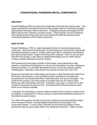
  • 4. . A controlled amount of mixed powder is automatically gravity-fed into a precision die and is compacted. Usually this is done at room temperature at compaction pressures as low as 138 MPA (10 tons per square inch) to as high as 827 MPa (60 tons per square inch) depending on the density requirements of the part and powder being pressed. Normally the compaction pressures are 345 to 690 MPa (25 – 50 tons per square inch). The compacted or “green” part has the size and shape of the finished part when ejected and has sufficient green strength to be handled and transported to the sintering furnace. In the sintering step, the green compact is placed on a mesh belt, and slowly moves through a controlled atmosphere furnace where the parts are heated to a temperature below the melting point of the base metal, held at the sintering temperature and then cooled. The sintering step transforms compacted mechanical bonds between the powder particles into metallurgical bonds by a solid state transformation process PM MATERIALS Metal Powders are precisely engineered materials that meet a wide range of performance requirements. These engineered materials offer wide latitude to develop materials with properties tailored to the application through metal alloying. These engineering properties are affected by several factors that include material type, powder fabrication process and the component manufacturing process. Basically four methods are used to produce powder: atomization, chemical, thermal and electrolytic. Choosing a method is determined by the economics, raw material and the desired particle shape, size and size distribution. The particle shape, size and size distribution profoundly affects the way the powder behaves during die filling, compaction and sintering. The range of shapes can be irregular, flake, dendritic and sponge (porous). Figure I displays the morphology of these shapes for various powders. 4
  • 5. (Typical metal powder particle shapes: atomized Cu, water atomized Fe, sponge Fe, electrolytic Cu - upper left to lower right) Figure I There are three types of powders. The first type is an admixed powder, so called because elemental powders such as copper, nickel and graphite are added to a base element powder such as iron or copper. These powders are used in circumstances where high purity is essential to material properties. Use of these elemental powders gives a manufacturer a lot of choice in tailoring the mixture to design requirements by mixing with other powders before pressing and sintering. However, elemental powders exhibit lower yield strength than prealloyed powders, allowing them to deform more readily during compaction, thereby improving density and green strength. They do not however, display the same degree of homogeneity of prealloyed powder during normal sintering. Partially alloyed powder is composed of two or more elements where the alloying additives are diffusion bonded to the base powder during the powder manufacturing process. This is done to enhance the compressibility of the base powder. These powders tend to be non-homogeneous, and therefore have diverse microstructures, but controllable phases. The chemistry can be closely controlled which enhances dimensional control. These materials also tend to have excellent fracture toughness. The last category, prealloyed powder, is typically atomized from alloyed furnace melts. Each particle has the same nominal composition as the next. Prealloyed powders yield homogeneous phase constituents throughout the microstructure. Prealloying is used to achieve alloys that are difficult to achieve by mixing elemental powders, such as stainless steel. In some cases, there are other additives in the powder mixtures, added for purposes such as lubrication, organic powders that vaporize during sintering to produce specific microporosity for filter applications and organic binders that allow the feedstock to be molded like the materials used in plastic injection molding. In addition to the metallurgical and chemical properties derived from the materials, there are a number of other properties that are important to a PM material. They include particle size distribution, particle shape, flow rate, bulk density, compressibility, green strength and the spring-back characteristics of the powder. Each of these properties has an effect on the workability, for lack of a better word, and the final characteristics and performance of a component. 5
  • 6. THE PRESSING CYCLE The adjacent figure (FIGURE II) offers a schematic analysis of the compacting process in a traditional PM press. Figure II The pressing cycle begins with the die receiving a charge of the mixed powder, delivered to the cavity by a feeder shoe that slides across the top of the tool set. The volume fed into the die is controlled by the relative position of the lower punch in the die. Once filled, the feed shoe withdraws and the next part of the cycle occurs as the upper and lower punches compress the powder into the die shape. When this step is completed, the upper punch withdraws and simultaneously, the lower punch rises, ejecting the pressed compact, and once clear, the feeder shoe pushes the compact away from the die cavity and another cycle of powder charging begins. 6
  • 7. Powder characteristics have considerable impact on the final outcome of this portion of the process, particle shape effects bulk flow rate, bulk flow effects final density and the amount of powder delivered to the tooling, and compressibility effects the final density of the component. Consistent delivery of a specific amount of powder and exact repeatability of the relative motion of the punches in the die set is essential to consistent component properties. The behavior of powder during compaction significantly affects the properties. During the early stage of compaction, the particles reorient to a denser particle packing level with less microporosity, thus increasing surface contact between particles. As the compaction increases, plastic deformation of the particles occurs before the final stage of compaction when cold welding and interlocking of the particles occurs, imparting sufficient strength to the green part for ejection and further handling. The goal during the compaction cycle is to impart uniform density throughout. The mechanics of compaction are largely governed by friction between the die and the powder and between the powder particles. Hence, tooling is a critical element in the fabrication process. The suitability of a component for PM manufacture depends essentially on the issues of whether suitable, compaction tooling can be designed and built. There is no known theoretical limit to the size of a PM component. The final density and the available press size are the practical limits. As a practical guide, the projected area (area perpendicular to the pressing direction) usually is between 4 and 16,000 mm2 (.006 and 25 square inches), with length between 0.8 to 150 mm (.03 and 6 inches), although 75 mm (3 inches) is the practical maximum. There are parts weighing 11.4 kilograms (25 pounds) in production today. Figure III identifies the elements of a tool set which usually consists of a die body or mold, upper and lower punches and in some cases, one or more core rods. Figure III 7
  • 8. The initial cost of PM tooling depends upon the level of sophistication of the component to be produced. The tooling must be robust enough to last from several hundred thousand cycles to over a million cycles without wear and damage. The tools are subjected to high compaction pressures, often as high as 690 MPa (50 tsi) for some steel components, as well as the abrasive characteristics of the powders. The die set must be able to withstand radial pressure during compaction and hold tolerance in the horizontal direction of the component. The die set also tends to experience the most wear, especially along the walls due to the ejection motion of the green part. Its design must consider distribution of the gravity fed powder and the part size. Wider parts are possible if perpendicular dimensions are reduced so that the maximum projected area is not exceeded. Punches transmit pressure to the powder in the die cavity. Punches must be able to resist expanding under repeated compaction cycles. The punches must possess high compressive yield strength, toughness and fatigue strength. Core rods are used to shape through holes in the component. Like the dies, core rods should be made from cemented carbides. Cemented carbides impart high hardness and superior wear resistance to tool sets. During the compacting phase, core rods are subjected alternately to high compressive and high tensile stresses, especially if they are thin or have complicated profiles. PM components are typically classified into one of four classes according to their complexity. The complexity refers to the motion necessary to form a component. Class one refers to simple one level parts with a low length/diameter ratio. Class two components have a higher l/d ratio and require that the punches more from both directions to make sure that density is as uniform as possible throughout the component. Class three components are two level parts that must be pressed from two directions and Class four components are multi-level components that require pressing from two directions. Complex components formed using multiple punches and core rods can have five or more levels depending upon the complexity of the press. Today’s presses enable parts to range between simple, single level shapes to complex, eight level shapes. SINTERING The traditional furnace found in the PM industry is a mesh belt furnace with three operating zones; a pre-heat or de-lube zone, a hot zone and a cooling zone. The furnaces usually operate between 1120 to 1150 degrees centigrade (2050 and 2100 degree F) for ferrous parts and 790 to 845 degrees centigrade (1450- 1550 degrees F.) for bronze materials. The trip through the furnace for a single part takes about 2 to 3 hours, depending upon the size of the part. Some components are 8
  • 9. sintered at a temperature 300 degrees Fahrenheit higher, a process called high temperature sintering, an effort made to enhance mechanical properties. Another variation on the process is called sinter-hardening, accomplished by using a controlled cooling rate in the cooling section of the belt furnace, transforming the steel matrix of a ferrous part to martensite, thereby eliminating the need for a secondary hardening step. SECONDARY OPERATIONS With the exception of repressing, impregnation and infiltration, a sintered PM component can be finished or treated, if necessary, just like any other metal component. PM components can be plated or coated for corrosion resistance and can also accept a black oxide coating to act as a paint base. Deburring can be performed to relieve sharp edges and ferrous parts can be burnished to control size and surface finish. Ferrous PM components can be successfully welded using just about any welding technique, given allowances for density, alloy composition, proper joint design and elimination of contaminants. Furnace brazing is often used to join other materials. PM components can be heat treated to improve strength and hardness and can be steam treated to make the surface hard and more wear resistant and well as contributing to improved corrosion resistance and the sealing of porosity. Repressing or coining is performed on PM components to densify or modify the surface shape and provide stricter dimensional control. This can also be achieved by sizing a component. Oil impregnation, used on PM self-lubricating bearing components since the late 1920’s, involves either soaking or vacuum processing. The components can absorb between 12 and 30 % oil by volume. Resin impregnation is performed on PM components to improve machinability or to prepare the surface for plating by making the surface liquid or gas tight and the surface “pore free”. Infiltration is a secondary process step used to either improve strength or seal parts and make them gas or liquid tight. Optional, like resin impregnation, it can also be used to enhance machinability and improve ductility and prepare parts for plating. It is not used to prevent PM defects. DESIGN DETAILS As mentioned above, holes are produced by core rods, which can be round, D-shaped, or include keyways or splines. They can also be used to provide lightening holes to reduce the projected pressing area. 9
  • 10. Wall thickness is always a careful consideration. Since die fill is important to get uniform density, long thin walls are a challenge and are seldom less than 1.52 mm (.060 inches) or have a length to thickness ratio exceeding 8 to 1. Thin walls result in fragile tools. Flat components pose a distortion problem during sintering. As such, flat parts are not the best application for PM. Often, repressing is required to improve flatness. Most PM components do not require draft on the sides of parts. Generally, fillet radii are most desirable. Tooling with generous fillets tends to last longer and result in higher component manufacturing speeds and greater tool integrity. Chamfer is a feature employed to prevent burring on part edges. Countersinks are formed by a punch around a hole to accommodate a screw or a bolt head. Flanges are produced by machining a shelf or step into the die. Bosses are forming cavities often located in punch tools. There are a few rules about depth of cavity exceeding part heights, generally restricted to less than 15%. A hub feature on a part should include a generous radius between the hub and the flange section and to maximize the space between hub outside diameter and gear or sprocket root diameters. Studs with drafted sides can be made like bosses, however, always consider the fragility of the green compact prior to sintering. Grooves can be pressed into either end of a part from projections on the punch face. Deep, narrow slots require fragile tooling and should be avoided. Undercuts on the horizontal plane (perpendicular to the pressing direction) cannot be formed, except when machined as a secondary operation, as they inhibit part ejection. If there is a juncture undercut, the alternative is to press a semicircular groove at the horizontal portion of the juncture. TOLERANCES In general, the dimensional tolerances that can be held in the PM process compare favorably with other metal forming processes. The tighter the tolerances, the greater the cost. Economically, tolerances no closer than necessary should be specified. The limits on tolerances depend on orientation of the dimension to the pressing direction, 10
  • 11. size, component complexity type of material, process variations and secondary operations. Radial dimensions are controlled by the dimension of the tools, while the axial dimensions are controlled by the motions of the press and the accuracy of the fill, thus requiring more latitude. Dimensional tolerances are proportional to the size of the part in the radial direction. Complex parts require increased tool complexity and thus more relative tool movement and the press movements contribute to component tolerances. Run-out tolerances on components with a hole, such as a gear, is affected not only by die accuracy, but also by the required running clearances of the tool set and the condition of the compaction press. Flatness is a function of component thickness and surface area. Thinner parts will tend to distort during sintering and shapes with unequal thickness may have density variations which will make flatness difficult to maintain. Powder formulation can affect components with variations in density, chemistry and reaction to the furnace atmosphere during sintering. Tool wear is an obvious source of variation in tolerancing components. Coining or sizing can improve tolerances. The following table (I) offers typical tolerances for a ferrous PM component measuring up to 100 mm (4 inches) in diameter and 25 mm (1inch) thick. Table I Pressed and Sintered Tolerances Practical Possible mm (in.) mm (in.) Length (+/-) 0.190 .0075 0.130 .005 Inside diameter (+/-) 0.100 .004 0.050 .002 Outside Diameter (+/-) 0.100 .004 0.050 .002 Concentricity 0.150 .006 0.100 .004 Flatness on ends 0.130 .005 0.100 .004 Parallelism of ends 0.130 .005 0.100 .004 Engineering Properties The first three properties of density, porosity and permeability are inter-related. Porosity is the converse of density which is often expressed as relative density, the ratio of a part’s density to that of its pore-free equivalent. The most common approach is to express the density in grams per cubic centimeter. Porosity is present as a network of interconnected pores that extend to the surface like a sponge or as a number of closed holes within the part. In the first case, porosity is important to the function of the design. In the latter case, less porosity is better. The porosity is a controllable function of the 11
  • 12. raw material and processing techniques. Permeability can be designed into a PM component to vary between a highly restricted to open flow. Like wrought metals, PM components and materials use ultimate tensile and yield strength to indicate the strength of an alloy. This property is heavily dependent upon density. Impact energy is also affected by density. In some PM material systems, such as stainless steels, the yield strength may exceed the strength of wrought materials. Ductility is relatively low in PM materials due to the presence of pores in the material. This property can be improved by hot or cold repressing and resintering. Hardness of PM parts cannot be directly compared using standard hardness testing equipment scales. It is measured as apparent hardness, which takes into account the combination of particle hardness and porosity. Standard testing equipment often displaces particle or sees excessive compression of the surface. Corrosion resistance is hampered by the porous nature of PM components, but stainless steel parts have relatively good corrosion resistance. Other non-ferrous alloys have corrosion resistance similar to wrought components. Excellent surface finish is inherent is PM components. The overall smoothness and surface reflectivity depends upon density, tool finish and any secondary operations. Profilometer readings on PM components are taken with a chisel stylus to account for pores of varying sizes. PM finishes compare well with wrought or cast components Like conventional wrought steels, PM components are hardenable. Table II is a comparative sample of PM properties with a wrought material (4340). C NI CU Mn CR T.S. Y.S Elong Hardness MPa (ksi) MPa (ksi) % 4340 * .4 1.65 – .6 - .8 .7 - .9 1240 1160 17 39 @1000 F 2.00 (180) (168) HRC FN – 0208 .6 - 1.0 – 0.0 - 1340 1240 .5 42 (180 HT) 7.4 g/cm 3 .9 3.0 2.5 (195) (180) HRC FC – 0205 .3 - 1.5 – 690 620 .5 36 (-90HT) 7.0 g/ cm 3 .6 3.9 (100) (90) HRC ss-316L 0-.3 10 -14 0-2 16 -18 280 140 18.5 20 HRB 6.6 g/cm3 (41) (20) * Metals Handbook – 4340 tempered @ 1,000°F - ASM International, Volume 1, ninth edition, p 426. 12
  • 13. ADDITIONAL PM “SHAPE” TECHNOLOGY In addition to conventional “press and sinter” PM technology, there are a number of allied metalforming techniques that offer design engineers options and choices when designing components. Some of these techniques would be characterized as non- conventional PM applications. If a designer is trying to develop an application that has three axes of design freedom and employs metal powders, the design choice for relatively small parts and large volumes is metal injection molding. The process is analogous to plastic or ceramic injection molding and can produce metal components with exceptional dimensional tolerance capabilities, unique metallurgical properties and require no machining. In general, parts are small, less than 500 grams, but this is changing with the introduction of new binder materials and the deployment of larger presses and more efficient furnaces for debinding and sintering. The part shown in Figure IV is an instrumental Figure IV sensor control valve for chemical and oil flow control. It was made from a 50-50 nickel – iron alloy that enables a magnetic flux to be applied through the body of the assembly. It replaced a four-part assembly. While we have not discussed the magnetic characteristics and capabilities of PM, this component is an axial flux stator. This example, figure V, of PM’s capabilities replaced 13
  • 14. Figure V a laminated electrical steel assembly and enables the magnetic flux to move in three dimensions, not just two. Another unique shape for our industry is this titanium softball bat outer shell (Figure VI). Figure VI This application was formed using cold isostatic pressing and is an excellent example of what can be achieved with a little ingenuity. The shell is subsequently hot isostatically pressed. The only secondary operations are surface conditioning and cutting to length. The shell has an ultimate tensile strength of 150,000 psi and 12 % elongation. Hot isostatic pressing is becoming more prevalent with higher volume applications on the near horizon due to faster cycling of HIP equipment. Very large, three thousand pound near net shape compacts are possible using HIP. In addition, to their size, HIPing is 14
  • 15. being used with material systems such as titanium –aluminides. Again demonstrating the ability of PM to enable cost effective fabrication of unusual alloy combinations. Spray forming is a process used to produce semi-finished mill products in the form of billets, tubes and sheet or plate. This is a sequential stage process consisting of liquid metal atomization, and droplet consolidation to produce a near net shape. The products typically have a close to fully dense and fine equiaxed grain structure. The mechanical properties meet or exceed those of ingot processed alloys. Metal matrix composites, the most popular being aluminum-silicon carbide particulate reinforced materials, are frequently being used in aerospace, sporting goods products and electronic thermal management component manufacture. The process employed is usually cold isostatic pressing followed by hot extrusion or forging to full density. The last PM forming technique I would like to discuss briefly is powder forging of metal powder. Generally, the practice is to manufacture a “green” compact called a preform, sinter it, and then restrike/forge the preform to the required final density. This process results in a product with wrought properties. FINAL COMMENTS The real advantage of PM is to cost effectively produce large volume, highly toleranced, metal components. The ongoing debate has always centered on properties, such as strength and size. As you can see from the above comments, PM is rapidly overcoming these modest objections as material selection and material characteristics are being engineered to specific applications and requirements. Flexibility and knowledge of process variables is the key for both the end-user and the component manufacturer. Non-conventional PM applications are effectively dealing with size constraints and metal injection molding can deal with any part geometry you can imagine. We, as an industry, see challenging new horizons that only require a little inspiration, ingenuity and persistence. 15