Milling
•Descargar como DOCX, PDF•
0 recomendaciones•1,635 vistas

Milling is a machining process that uses a rotating multi-toothed cutter to remove material from a workpiece. Milling machines can hold one or more cutters and precisely rotate and index workpieces to cut flat, curved, and threaded surfaces to close tolerances. Milling machines are classified based on their design and include column and knee mills, manufacturing mills, and planer mills. The principal parts of a column and knee mill include the base, column, knee, saddle, overarm, spindle, arbor, and various milling cutters. Milling cutters come in different shapes like plain, side, angle, and end mills to perform operations like slotting and profiling.

Recomendados
Más contenido relacionado
La actualidad más candente
La actualidad más candente (20)
Destacado
Destacado (17)
Similar a Milling
Similar a Milling (20)
Más de Krishna Gali
Más de Krishna Gali (20)
Último
Último (20)
Milling
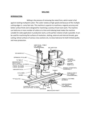
- 1. MILLING INTRODUCTON: Milling is the process of removing the metal from, which metal is fed against rotating multipoint cutter. The cutter rotates at high speed and because of the multiple cutting edges it a very fast rate. This machine is superior to machines a regards accuracy and better surface finish and is designed for machining a variety of tool room work. The machine can hold one or more number of cutters at a time and indexing head makes the machine suitable for wide application in production work, as the perfect rotation of job is possible. It can be used for machining flat surfaces of revolution, slotting, external and internal threads, gear cutting, helical surfaces of various cross-sections etc, to close tolerance for both limited quality and mass production.
- 2. CLASSIFICATION OF MILLING MACHINES: There are many types of milling machines, from the simple hand mills to complex shape , controlled machines, but the choice of any particular machine is determined primarily by the nature of the work t be undertaken both in relation to the size and operation to be performed . The usual classifications according to the general design of the milling machine are: 1. Column and knee type a) Hand milling machine b) Plain milling machine c) Universal milling machine d) Omniversal milling machine e) Vertical milling machine 2. Manufacturing or fixed bed type a) Simplex milling machine b) Duplex milling machine c) Triplex milling machine 3. Planer type machine a) Rotary table milling machine b) Drum milling machine c) Planetary milling machine d) Pantograph, profiling and tracer controlled milling machine.
- 3. PRINCIPLE PARTS OF MILLING MACHINE The principle parts of the column and knee type milling machine are as follows: Base: The base of the machine is a grey iron casting accurately machined on its top and bottom surfaces and serves as a foundation member for all the other parts which rest upon it. It carries the column as its one end. In some machines, the base is hollow and serves as a reservoir for cutting fluid.
- 4. Column: The column is the main supporting frame mounted vertically on the base. The column is box shaped heavily ribbed inside and houses all the driving mechanisms for the spindle and table feed. The front vertical face of the column is accurately machined and is provide with dovetail guide ways for supporting the knee. The top of the column is finished to hold an over arm that extends outward at the front of the machine. Knee: The knee is a rigid grey iron casting that slide up and down on the vertical ways of the column face. The adjusting if height is affected by an elevating screw mounted on the base that also supports the knee. The knee houses the feed mechanism of the table and different controls to operate it. The top face of the knee forms a slide way for the saddle to provide cross travel of the table. Saddle: On the top of knee is placed the saddle, which slides on guide ways exactly at 90 degrees to the column face. A cross feed screw near the top of the knee engages a nut on the bottom of the saddle to move it horizontally, by hand or power, to apply cross feed. The top of the saddle is accurately machined to providing guide ways for the table. Over hanging arm: The overhanging arm that is mounted on top of the column extends beyond the column face and serves as a bearing support for the other end of the arbor. The arm is adjustable so that the bearing support may be provided nearest to cutter more than one bearing supporting may be provided for the arbor.
- 5. Front brace: The front brace is an extra support that is fitted between the knee and the over arm to ensure further rigidity to the arbor and the knee. The front brace is slotted to allow for the adjustment of the knee relative to the over arm. Spindle: The spindle of the machine is located in the upper part of the column and receives power from motor through belt gears and clutches and transmit it to the arbor the front end of the spindle just projects from the column face and is tools and arbor may be inserted the accuracy in metal machining by the cutter depends primarily on the accuracy, strength and rigidity of the spindle. Arbor: An arbor may be considered as an extension of the machine spindle on which milling cutters are securely mounted and rotated. Arbors are made with taper shanks for proper alignment with the machine spindle of the arbor conforms to the over Morse taper or self release taper whose value is 7:24. The arbor may be supported at the furthest end from the overhanging arm or may be of cantilever type which is called stud arbor. Milling cutters: The milling cutters are revolving tools having one or several cutting edges of identical from equally spaced on the circumference of the cutter. The cutting elements are called teeth which intermittently engage the work piece and remove material by relative movement of the work piece and cutter. The milling cutters re classified according to their shapes. Plain milling cutter: The plain milling cutter are cylindrical in shape and have teeth on the circumferential surface only. The milling cutters are intended for the production of flat surfaces parallel to axis of rotation of the spindle. The cutters teeth may be straight or helical according to the size of the cutter. Very wide plain milling cutters are termed as slab cutter. These cutters nicks are uniformly distributed on the entire periphery of the cutter. The object of the nicks is
- 6. to break up the chips and enable the cutter to take a coarse feed. The different varieties of the plain milling machine cutters are 1. Light duty 2. Heavy duty 3. Helical plain milling cutter. Side milling cutter: The side milling cutter has teeth on its periphery and also on one or both of its sides. The side milling cutters are intended for removing metal from side of a work. The side milling cutters are available from 50 to 200 mm in diameter. The different types of side milling cutters are: 1. Staggered teeth side milling cutter 2. Half side milling cutter 3. Inter locking milling cutter Angle milling cutter: The angle milling cutters are made as single or double angle cutters and are used to machine angle other than 90degrees the cutting edges are formed at the conical surfaces around the periphery of the cutter. The different types of angle milling cutters are 1. Single angle milling cutter 2. Double e angle milling cutter End milling cutter: The end mills have cutting teeth on the end as well as on the periphery of the cutter. The periphery teeth may be straight or helical and the helix may be right hand or left hand. The end mills are used for light milling operation like cutting slots, machining accurate holes, producing narrow flat surfaces and for profile milling operations. The different types of end milling cutters are 1. Taper shank end mill cutters 2. Straight shank end mill 3. Shell end mill
- 7. Slotted milling cutter Shell end milling cutter Conventional or Up milling: In up milling each tooth starts the cut in clean metal and has not to break through the possible surfaces scale and thus cutter is not subjected to large forces and vibrations. The cutter force is high at the end of cut and direction is such as to lift work from the fixture. Here the chips accumulate ahead of the cutting region chip thickness is higher and therefore there is greater tendency for chip to weld to cutter has strong rubbing action. Here the cutter teeth move opposite in direction to feed. This is most widely used.
- 8. Conventional milling cutter Climb or Down milling: The down milling is the process of removing metal by a cutter which is located in the same direction of travel of the work piece. Here max. Chip thickness occurs at the end of cut. Surface finish is good here. This method is very efficient and used for large chip removal. Coolant is applied easily in down milling. The cutter tooth starts removing metal immediately on reaching work surface, without sliding. The down milling operation cannot be used on old machines due to backlash error that may be present between the lead screw of the able and the nut. The back lash error causes the work to be pulled below the cutter when the cut begins and leave the work free when the cut is terminated. Down milling cutter
- 9. Indexing: The operation of the rotating the job through a required angle between the success cuts is termed as indexing. This is accomplished with the help of milling machine attachment known as dividing head. It divides the job periphery two equal number of division. Dividing head to rotate a job needs (a) a device to rotate the job (b) a source that can be ensure that a job has been rotated through desired angle. The first requirement -is obtained by index crank and second by index plate. The index plate has no. of holes equally spaced concentrically.
- 10. The following index pates are available: PLATE 1: 15, 16,17,18,19 PLATE 2: 20, 21,22,27,29 PLATE 3: 31, 33,37,39,41 PLATE 4: 43, 47, 49 METHOD OF INDEXING 1. Direct indexing 2. Simple or plain indexing 3. Compound indexing 4. Differential indexing 5. Angular indexing.