SlideShare una empresa de Scribd logo
1 de 16
CHAPTER 1
                                    DC MACHINES


1.1 INTRODUCTION

Energy is needed in different forms:

•   Light bulbs and heaters - electrical energy
•   Fans and rolling miles - mechanical energy
•   Need for energy converters


                                        Figure 1.1

•   DC generator – supply current to the load
•   DC motor – need current from the supply
•   AC electric supply - AC machines (synchronous and asynchronous)
•   DC electric supply - DC machines

•   Advantages of DC Machine
    (i) Adjustable motor speed over wide ranges
    (ii) Constant mechanical output (torque)
    (iii)Rapid acceleration or deceleration
    (iv) Responsive to feedback signals


                                                                       1
Figure 1.2 : DC machine Construction

1.2 GENERATION OF AC SIGNAL

•   Generator needs something to rotate or move itself.
•   It is called the prime mover.
•   The shaft of the prime mover will be coupled to the shaft of the generator so that the
    generator can rotate once the prime mover rotates.
•   In a big system, they normally used 3-phase induction motor.
•   But, in small scale machine, they can use a mechanism to rotate the generator which
    then generated electricity.
                                                                      coil


                                                                      Slip ring:used to
                                                                      generate ac signal
                                                                      Carbon brush: used to
                                                                      collect output voltage (ac
                                                                      signal)
                                     carbon brush
              Figure 1.3: Physical Arrangement of AC Generating Method


                                                                                              2
Figure 1.4 : Emf generated at various instant (angle position)

1.3 GENERATION OF DC SIGNAL

•   The generating of DC signal can be done by replacing the slip ring with commutator
    so that rectification process can happen.
•   Commutator can generate dc signal.
•   This is done through rectification or commutation process; which converts ac signal
    into dc mechanically.
•   Therefore a commutator is called a mechanical rectifier.


     Carbon
                                                                   commutator:used to
      brush                                                        generate dc signal
                                                                   Carbon brush: used to
                                                                   collect output voltage
                                                                   (dc signal)

                                                    commutator

              Figure 1.5 : Physical Arrangement of DC Generating Method


                                                                                            3
Figure 1.6: AC is converted into DC Signal through Commutation Process

1.4 EMF GENERATED ON DC MACHINE

The EMF generated:-
                                               zNP
                                     EMF = 2       φ
                                               c60

where          z = no of conductors in the armature circuit
               c = no. of parallel path
               N = speed in rpm
               Φ = flux/pole (Wb)
               P = no. of pole pair


                      Figure 1.7 : Permanent Magnet Dc Machine


                                                                                 4
Example 1

If the no-load voltage of a separately excited generator is 135 V at 850 rpm, what will be
the voltage if the speed is increased to 1000 rpm? Assume constant field excitation.

Solution
         2 zPNφ
EMF =
           c60
     2 zP
K=
     c60
Therefor ,
E1 = KN 1φ1
E 2 = KN 2φ 2
Constant field excitation:- i1 = i2 , ⇒ φ1 = φ 2
E1    KN 1φ1     N
   =          = 1
E 2 KN 2φ 2 N 2
        E1 N 2 1000rpm(135V )
E2 =          =               = 158.8V
         N1       850rpm


Example 2

A separately excited generator has no-load voltage of 140 V when the field current is
adjusted to 2 A. The speed is 900 rpm. Assume a linear relationship between the field
flux and current. Calculate:
(i)    the generated voltage when the field current is increased to 2.5 A. Assume N1=N2.
(ii)   the terminal voltage when the speed is increased to 1000 rpm with the field
       current set at 2.2 A.

Solution

V1 = 140V , I F 1 = 2 A, N 1 = 900rpm
φαI F

(i)      I F 2 = 2.5 A
         E1      KN 1φ1  I
              =         = F1
         E 2 KN 2φ 2 I F 2
                E1 I F 2 140(2.5)
         E2 =           =         = 175V
                 I F1       2

(ii)     N 2 = 1000rpm, I F 2 = 2.2 A, V2 = ?


                                                                                         5
E1   KN 1φ1  NI
           =        = 1 F1
        E 2 KN 2φ 2 N 2 I F 2
               E1 N 1 I F 2 140(1000)(2.2)
        E2 =               =               = 171.11V
                N 2 I F1        (900)2


1.5 DC MACHINE CONSTRUCTION


                                   rotor/armature
                                                               pole


                          Figure 1.8 : DC Machine Construction

DC motor principles

•   DC motors consist of rotor-mounted windings (armature) at the rotor side and
    stationary windings (field poles) at the stator side.


                                                                                   6
•   In all DC motors, except permanent magnet motors, current must be conducted to the
    armature windings by passing current through carbon brushes that slide over a set of
    copper surfaces called a commutator, which is mounted on the rotor.
•   The commutator bars are soldered to armature coils.
•   The brush/commutator combination makes a sliding switch that energizes particular
    portions of the armature, based on the position of the rotor.
•   This process creates north and south magnetic poles on the rotor that are attracted to
    or repelled by north and south poles on the stator, which are formed by passing direct
    current through the field windings.
•   It's this magnetic attraction and repulsion that causes the rotor to rotate.


                         Figure 1.9 : DC Machine Construction


1.6 MACHINE WINDINGS

•   Machine winding can be divide into 2:-
    (i)   armature winding (rotor side)
    (ii)  field winding (stator side)


                                                                                         7
Machine Winding


                     Field winding                                         Armature Winding


      Separately excited                  **Self excited
     -no direct connection           -direct connection between
     between armature circuit        armature circuit and the
     and the field circuit           field circuit


                  Series                                          Compound
                                     Shunt excitation
                excitation                                        excitation


                     Figure 1.10: Winding Connection in DC Machine

SELF-EXCITED FIELD WINDING

•   In self-excited dc machine, there are three types of excitation method namely:
    (i)     Series Excitation: the field winding is connected in series with the armature
            circuit.
    (ii)    Shunt Excitation: the field winding is connected in parallel with the
            armature circuit.
    (iii)   Compound Excitation: the field winding are connected in series and parallel
            with the armature circuit.

•   The schematic diagrams for the three types of these machines are illustrated in Figure
    1.11.
•   The difference between dc motor and dc generator is in terms of the current
    direction.
•
      In dc generator: armature current, Ia is supplied by the armature.
        In dc motor: armature current, Ia is received by the armature.


                                                                                         8
(a) DC Series machine

                                  Rf                                                                                      Rf
                                                   IL                                                                                     IL
      Ra                                                                               Ra
                                                                                                                                               dc supply


                                                   DC loa d
                       Ia                                      VT                                           Ia
                                                                                                                                               VT
      1.0 k


                                                                                      1.0 k
   1.0m                                                                               1.0m
                                                                                       5.0
                  +


                                                                                                       +
                       Eg                                                                                   EC
                  -


                                                                                                       -
Generator: Eg = VT + Ia(Ra + Rf)                                                       Motor: Ec = VT - Ia(Ra + Rf)


(b)DC Shunt machine

                                                       IL                                                                           If              IL
                                       If
    Ra                                                                                         Ra
                                                         DC loa d
    1.0 k


                                                                                                                                                    dc supply
                                                                                               1.0 k
   1.0 m


                                                                                              1.0 m


                       Ia              Rf                           VT                        5.0
                                                                                                                     Ia             Rf
                                                                                                                 +                                  VT
                  +


                       Eg                                                                                            Ec
                                                                                                                 -
                   -


Generator: Eg = VT + IaRa                                                                     Motor: Ec = VT - IaRa


(c) DC Compound machine

                            Rf2                                                                                  Rf2

                                                              IL                                                               IF              IL
   Ra                                   IF                                              Ra
                                                                                                       Ia
                                                               D Cload


              Ia                             Rf1                          VT                                                        Rf1        dc supply
                                                                                                                                                            1,0m


                                                                                                                                                           1,0
                                                                                                                                                           1,0m
                                                                                                                                                           DCM1
                                                                                                                                                            1,0m
              +


                                                                                                                                                VT
                                                                                                 +


                   Eg                                                                                       Ec
                                                                         D CM1
              -


                                                                         1,0m
                                                                         1,0m


                                                                                                  -


Generator: Eg = VT + Ia(Ra + Rf 2)                                                       Motor: Ec = VT - Ia(Ra + Rf 2)

                                                                                 Figure 1.11
 **           Eg = generated emf
              Ec = counter emf
                                                                                                                                                                   9
1.7 POWER FLOW DIAGRAM


Power flow diagram is normally represented as a fish bone.


 Input Power = Output + Losses
 Losses can be divided into 2:-
    (i)     Copper losses (Armature copper loss , Pca) and (Field copper loss,Pcf)
    (ii)    Iron losses, Pµ (friction, stray, windage,mechanical losses)


 For DC Generator:           Pin = Pout + Total losses
                       where Pout = VTIL

 For DC Motor:               Pin = Pout + Total losses
                       where Pin = VTIL

 Total losses = Pca + Pcf + Pµ


                                                                                     10
POWER FLOW DIAGRAM FOR DC GENERATOR


  DC SERIES
                    Pµ
                                      Pcf

  Pin                                          Pout= VTIL

                            Pca


  DC SHUNT
                    Pµ
                                      Pcf

  Pin                                          Pout= VTIL

                            Pca


  DC COMPOUND
                    Pµ
                                      Pcf1

  Pin                                          Pout= VTIL

                            Pca         Pcf2


                                                            11
POWER FLOW DIAGRAM FOR DC MOTOR


   DC SERIES
                             Pca
                                                         Pµ

                                        Pm                            Pout
    Pin=VTIL

                                        Pcf

   DC SHUNT
                             Pca
                                                         Pµ
                                   Pm
   Pin=VTIL                                                          Pout

                                        Pcf


   DC COMPOUND
                             Pca
                                                         Pcf2

   Pin = VTIL                                        Pm              Pout
                                                                Pµ
                                        Pcf1

1.8 MOTOR TORQUE

For load torque@shaft torque@net torque@output torque:

       60 Pout
To =
        2πN

For mechanical torque:
     60 Pm
Tm =
     2πN

For loss torque:

       60 Pµ
TL =
       2πN


                                                                             12
1.9 EFFICIENCY

Generally efficiency is:

     Pout
η=
     Pin

For dc generator:

     Pout     VTIL
η=        =
     Pin VTIL + Losses

For dc motor:

     Pout Pm − Pµ
η=       =
     Pin   VTIL

Example 3

A short-shunt compound generator delivers 50 A at 500 V to a resistive load. The
armature, series field and shunt field resistances are 0.16, 0.08 and 200 Ω, respectively.
Calculate the generated EMF and armature current, if the rotational losses are 520 W,
determine the efficiency of the generator.

Solution


                      0.08 ohm

                                IF         IL       50 A
     0.16 ohm
                                           load


                                                             D CM1
                                                             1,0m


                       200 ohm
                                                             1,0m


                                                  500V       1,0m
                 -


            Eg
                 +


Pµ = 520W
Pout = VI = 500(50) = 25000W


                                                                                             13
500V
IF =           = 2.5 A
       200Ω
I a = I F + I L = 2.5 + 50 = 52.5 A

E g = VT + I a ( Ra + R f )
E g = 500 + (52.5)(0.08 + 0.16) = 512.6V

Pin = Pout + Ploss
Ploss = Pca + Pcf + Pµ = (52.5 2 )(0.16) + (52.5 2 )(0.08) + (2.5 2 )(200) + 520 = 2431.5W

      Pout       25000
η=         =                x100% = 91.13%
      Pin    25000 + 2431.5


Example 4

A 150 V shunt motor has the following parameters:
Ra = 0.5 Ω, Rf = 150 Ω and rotational loss 250 W. On full load the line
current is 19.5 A and the motor runs at 1400 rpm. Determine:
(i)     the developed power/developed mechanical power
(ii)    the output power
(iii)   the output torque
(iv)    the efficiency at full load


Solution

IL = 19.5A
N = 1400rpm

(i)      Pm = E c I a
         Ia = IL − IF
         I L = 19.5 A
                VT 150
         IF =      =    =1
                R F 150
         I a = 19.5 − 1 = 18.5 A
         E c = VT − I a Ra = 150 − 18.5(0.5) = 140.75V

         Pm = E c I a = (140.75)(18.5) = 2603.88W


                                                                                             14
OR :- Pm = Pin − Pca − Pcf
        Pm = VT I L − I a Ra − I F RF
                        2        2


        Pm = 150(19.5) − (18.5 2 )(0.5) − (12 )(150) = 2603.88W

(ii)    Pout = Pm − Pµ = 2603.88 − 250 = 2353.88W

               60 Pout 60(2353.88)
(iii)   To =          =            = 16.06 Nm
                2πN     2π (1400)

               Pout   P     2353.88
(iv)    η=          = out =         = 80.47%
               Pin VT I L 150(19.5)


                                                                  15
Tutorial 1

1. A 300 V compound motor has armature resistance 0.18 Ω, series field resistance 0.3 Ω
and shunt field resistance 100 Ω. The rotational losses are 200 W. On full load the line
current is 25 A and the motor runs at 1800 rpm. Determine:

(i)     the developed mechanical power
(ii)    the output power
(iii)   the output torque
(iv)    the efficiency at full load


2. A 120 V series motor has 0.2 Ω field resistance. On full load, the line current is 16.5
A. The output power is 1500 W and rotational loss is 150 W. Find the value of armature
resistance.


3. Briefly explain the difference between motor and generator of DC machine.


4. A compound DC motor rated at 415 V, 6 HP, 2000 rpm has armature resistance 0.18
Ω, series field resistance 0.3 Ω and shunt field resistance 100 Ω. The rotational losses
are 200 W. The full load line current is 40 A.

(i)     Find the developed mechanical power.
(ii)    Find the output power.
(iii)   Find the load torque.
(iv)    Find the efficiency of the motor.
(v)     Draw the power flow diagram for this type of motor.


5. A DC series generator delivers 100 kW at 10 kV to a load. The armature resistance is
20 Ω and the field resistance is 50 Ω. Calculate:

(i)     the generated emf, Eg
(ii)    the input power if the stray and friction losses are 400 W.


                                                                                         16

Más contenido relacionado

La actualidad más candente

synchronous generators
synchronous generatorssynchronous generators
synchronous generatorsSouvik Dutta
 
Drives lec 11_12_Braking of DC Motors
Drives lec 11_12_Braking of DC MotorsDrives lec 11_12_Braking of DC Motors
Drives lec 11_12_Braking of DC MotorsMohammad Umar Rehman
 
single-phase-induction-motor.ppt
single-phase-induction-motor.pptsingle-phase-induction-motor.ppt
single-phase-induction-motor.pptsivaramanpsr
 
Bldc motors in railway and metro
Bldc motors in railway and metroBldc motors in railway and metro
Bldc motors in railway and metroDilip Gy
 
Synchronous machines
Synchronous machinesSynchronous machines
Synchronous machinesAnu71
 
Multilevel inverter
Multilevel  inverterMultilevel  inverter
Multilevel inverterSyed Lateef
 
star delta auto starter with forward reverse and motor protection
star delta auto starter with forward reverse and motor protectionstar delta auto starter with forward reverse and motor protection
star delta auto starter with forward reverse and motor protectionBHUPATI PRADHAN
 
Dc motor construction
Dc motor constructionDc motor construction
Dc motor constructionRiyas S
 
Three Phase Synchonours Generator and AVR
Three Phase Synchonours Generator and AVR Three Phase Synchonours Generator and AVR
Three Phase Synchonours Generator and AVR Emre Öztoklu
 
Brushless DC Motors - EEERulez.BlogSpot.in
Brushless DC Motors - EEERulez.BlogSpot.inBrushless DC Motors - EEERulez.BlogSpot.in
Brushless DC Motors - EEERulez.BlogSpot.inRakesh Bhupathi
 
Basic Presentation on Speed control of induction motor
Basic Presentation on Speed control of induction motorBasic Presentation on Speed control of induction motor
Basic Presentation on Speed control of induction motorNileshBambhaniya2
 
Breaking,Types of Electrical Braking system, Regenerative Braking, Plugging ...
Breaking,Types of Electrical Braking system, Regenerative Braking,  Plugging ...Breaking,Types of Electrical Braking system, Regenerative Braking,  Plugging ...
Breaking,Types of Electrical Braking system, Regenerative Braking, Plugging ...Waqas Afzal
 
3phase induction motor
3phase induction motor3phase induction motor
3phase induction motorNaveen Sihag
 

La actualidad más candente (20)

synchronous generators
synchronous generatorssynchronous generators
synchronous generators
 
Drives lec 11_12_Braking of DC Motors
Drives lec 11_12_Braking of DC MotorsDrives lec 11_12_Braking of DC Motors
Drives lec 11_12_Braking of DC Motors
 
single-phase-induction-motor.ppt
single-phase-induction-motor.pptsingle-phase-induction-motor.ppt
single-phase-induction-motor.ppt
 
Bldc motors in railway and metro
Bldc motors in railway and metroBldc motors in railway and metro
Bldc motors in railway and metro
 
Dc motor
Dc motor Dc motor
Dc motor
 
Synchronous machines
Synchronous machinesSynchronous machines
Synchronous machines
 
Multilevel inverter
Multilevel  inverterMultilevel  inverter
Multilevel inverter
 
BLDC Motor
BLDC MotorBLDC Motor
BLDC Motor
 
star delta auto starter with forward reverse and motor protection
star delta auto starter with forward reverse and motor protectionstar delta auto starter with forward reverse and motor protection
star delta auto starter with forward reverse and motor protection
 
Types-of_dc_motor
Types-of_dc_motorTypes-of_dc_motor
Types-of_dc_motor
 
Dc motor construction
Dc motor constructionDc motor construction
Dc motor construction
 
Three Phase Synchonours Generator and AVR
Three Phase Synchonours Generator and AVR Three Phase Synchonours Generator and AVR
Three Phase Synchonours Generator and AVR
 
Dc motor prasad 55
Dc motor prasad 55Dc motor prasad 55
Dc motor prasad 55
 
Brushless DC Motors - EEERulez.BlogSpot.in
Brushless DC Motors - EEERulez.BlogSpot.inBrushless DC Motors - EEERulez.BlogSpot.in
Brushless DC Motors - EEERulez.BlogSpot.in
 
Synchronous generator
Synchronous generatorSynchronous generator
Synchronous generator
 
Basic Presentation on Speed control of induction motor
Basic Presentation on Speed control of induction motorBasic Presentation on Speed control of induction motor
Basic Presentation on Speed control of induction motor
 
Breaking,Types of Electrical Braking system, Regenerative Braking, Plugging ...
Breaking,Types of Electrical Braking system, Regenerative Braking,  Plugging ...Breaking,Types of Electrical Braking system, Regenerative Braking,  Plugging ...
Breaking,Types of Electrical Braking system, Regenerative Braking, Plugging ...
 
Electric Motors
Electric MotorsElectric Motors
Electric Motors
 
Speed control of dc motor
Speed control of dc motorSpeed control of dc motor
Speed control of dc motor
 
3phase induction motor
3phase induction motor3phase induction motor
3phase induction motor
 

Destacado

Ii20102011
Ii20102011Ii20102011
Ii20102011mkazree
 
Chapter5 dek 3143 dae 32303 9 (nota tambahan)
Chapter5 dek 3143 dae 32303 9 (nota tambahan)Chapter5 dek 3143 dae 32303 9 (nota tambahan)
Chapter5 dek 3143 dae 32303 9 (nota tambahan)mkazree
 
Chapter 3 induction machine
Chapter 3 induction machineChapter 3 induction machine
Chapter 3 induction machinemkazree
 
Chapter 2 transformer new
Chapter 2 transformer newChapter 2 transformer new
Chapter 2 transformer newmkazree
 
120102011
120102011120102011
120102011mkazree
 
Chapter 4 synchronous machine
Chapter 4 synchronous machineChapter 4 synchronous machine
Chapter 4 synchronous machinemkazree
 
Tutorial chapter 3 robotic
Tutorial chapter 3 roboticTutorial chapter 3 robotic
Tutorial chapter 3 roboticmkazree
 
Tutorial 2 amplitude modulation
Tutorial 2 amplitude  modulationTutorial 2 amplitude  modulation
Tutorial 2 amplitude modulationmkazree
 
Tutorial chapter 2 robotic
Tutorial chapter 2 roboticTutorial chapter 2 robotic
Tutorial chapter 2 roboticmkazree
 
Lab 6 microcontroller
Lab 6 microcontrollerLab 6 microcontroller
Lab 6 microcontrollermkazree
 
Lab 5 microcontroller
Lab 5 microcontrollerLab 5 microcontroller
Lab 5 microcontrollermkazree
 
Lab 4 microcontroller
Lab 4 microcontrollerLab 4 microcontroller
Lab 4 microcontrollermkazree
 
Lab 2 microcontroller
Lab 2 microcontrollerLab 2 microcontroller
Lab 2 microcontrollermkazree
 
Chp1 68000 microprocessor copy
Chp1 68000 microprocessor   copyChp1 68000 microprocessor   copy
Chp1 68000 microprocessor copymkazree
 
Foster-seely and Ratio Detector (Discriminator )
Foster-seely and Ratio Detector (Discriminator )Foster-seely and Ratio Detector (Discriminator )
Foster-seely and Ratio Detector (Discriminator )mkazree
 
Chp6 assembly language programming for pic copy
Chp6 assembly language programming for pic   copyChp6 assembly language programming for pic   copy
Chp6 assembly language programming for pic copymkazree
 
Lab 1 microcontroller
Lab 1 microcontrollerLab 1 microcontroller
Lab 1 microcontrollermkazree
 
Chapter 5 fm receivers
Chapter 5  fm receiversChapter 5  fm receivers
Chapter 5 fm receiversmkazree
 
Coal Fired Power Plant
Coal Fired Power PlantCoal Fired Power Plant
Coal Fired Power Plantmkazree
 
Communication Engineering - Chapter 6 - Noise
Communication Engineering - Chapter 6 - NoiseCommunication Engineering - Chapter 6 - Noise
Communication Engineering - Chapter 6 - Noisemkazree
 

Destacado (20)

Ii20102011
Ii20102011Ii20102011
Ii20102011
 
Chapter5 dek 3143 dae 32303 9 (nota tambahan)
Chapter5 dek 3143 dae 32303 9 (nota tambahan)Chapter5 dek 3143 dae 32303 9 (nota tambahan)
Chapter5 dek 3143 dae 32303 9 (nota tambahan)
 
Chapter 3 induction machine
Chapter 3 induction machineChapter 3 induction machine
Chapter 3 induction machine
 
Chapter 2 transformer new
Chapter 2 transformer newChapter 2 transformer new
Chapter 2 transformer new
 
120102011
120102011120102011
120102011
 
Chapter 4 synchronous machine
Chapter 4 synchronous machineChapter 4 synchronous machine
Chapter 4 synchronous machine
 
Tutorial chapter 3 robotic
Tutorial chapter 3 roboticTutorial chapter 3 robotic
Tutorial chapter 3 robotic
 
Tutorial 2 amplitude modulation
Tutorial 2 amplitude  modulationTutorial 2 amplitude  modulation
Tutorial 2 amplitude modulation
 
Tutorial chapter 2 robotic
Tutorial chapter 2 roboticTutorial chapter 2 robotic
Tutorial chapter 2 robotic
 
Lab 6 microcontroller
Lab 6 microcontrollerLab 6 microcontroller
Lab 6 microcontroller
 
Lab 5 microcontroller
Lab 5 microcontrollerLab 5 microcontroller
Lab 5 microcontroller
 
Lab 4 microcontroller
Lab 4 microcontrollerLab 4 microcontroller
Lab 4 microcontroller
 
Lab 2 microcontroller
Lab 2 microcontrollerLab 2 microcontroller
Lab 2 microcontroller
 
Chp1 68000 microprocessor copy
Chp1 68000 microprocessor   copyChp1 68000 microprocessor   copy
Chp1 68000 microprocessor copy
 
Foster-seely and Ratio Detector (Discriminator )
Foster-seely and Ratio Detector (Discriminator )Foster-seely and Ratio Detector (Discriminator )
Foster-seely and Ratio Detector (Discriminator )
 
Chp6 assembly language programming for pic copy
Chp6 assembly language programming for pic   copyChp6 assembly language programming for pic   copy
Chp6 assembly language programming for pic copy
 
Lab 1 microcontroller
Lab 1 microcontrollerLab 1 microcontroller
Lab 1 microcontroller
 
Chapter 5 fm receivers
Chapter 5  fm receiversChapter 5  fm receivers
Chapter 5 fm receivers
 
Coal Fired Power Plant
Coal Fired Power PlantCoal Fired Power Plant
Coal Fired Power Plant
 
Communication Engineering - Chapter 6 - Noise
Communication Engineering - Chapter 6 - NoiseCommunication Engineering - Chapter 6 - Noise
Communication Engineering - Chapter 6 - Noise
 

Similar a Chapter 1 dc machines new

DC Machines with explanation in detail of everything
DC Machines with explanation in detail of everythingDC Machines with explanation in detail of everything
DC Machines with explanation in detail of everythingOmer292805
 
dc-generators-unit-1.ppt
dc-generators-unit-1.pptdc-generators-unit-1.ppt
dc-generators-unit-1.pptQwer401863
 
chapter 3- DC motor.pptx
chapter 3- DC motor.pptxchapter 3- DC motor.pptx
chapter 3- DC motor.pptxAjayKumar4724
 
Electrical Machines.pdf
Electrical Machines.pdfElectrical Machines.pdf
Electrical Machines.pdfDarrienXavier
 
Chapter 4 synchronous machine
Chapter 4 synchronous machineChapter 4 synchronous machine
Chapter 4 synchronous machinemkazree
 
Rotating machines part 3
Rotating machines part 3Rotating machines part 3
Rotating machines part 3Loki Maha
 
DC_Machines_week_4.ppt
DC_Machines_week_4.pptDC_Machines_week_4.ppt
DC_Machines_week_4.pptkiran93845
 
DC-GENERATOR-UNIT-II.ppt
DC-GENERATOR-UNIT-II.pptDC-GENERATOR-UNIT-II.ppt
DC-GENERATOR-UNIT-II.pptprajwaleswa2004
 
Unit7-DC_Motors.ppt
Unit7-DC_Motors.pptUnit7-DC_Motors.ppt
Unit7-DC_Motors.pptAbeyuAssefa
 
Unit7-DC_Motors.ppt
Unit7-DC_Motors.pptUnit7-DC_Motors.ppt
Unit7-DC_Motors.pptArpanKumar79
 

Similar a Chapter 1 dc machines new (20)

DC Machines with explanation in detail of everything
DC Machines with explanation in detail of everythingDC Machines with explanation in detail of everything
DC Machines with explanation in detail of everything
 
dc-generators-unit-1.ppt
dc-generators-unit-1.pptdc-generators-unit-1.ppt
dc-generators-unit-1.ppt
 
physcis.pptx
physcis.pptxphyscis.pptx
physcis.pptx
 
chapter 3- DC motor.pptx
chapter 3- DC motor.pptxchapter 3- DC motor.pptx
chapter 3- DC motor.pptx
 
Electrical Machines.pdf
Electrical Machines.pdfElectrical Machines.pdf
Electrical Machines.pdf
 
Chapter 4 synchronous machine
Chapter 4 synchronous machineChapter 4 synchronous machine
Chapter 4 synchronous machine
 
DC MOTOR.pdf
DC MOTOR.pdfDC MOTOR.pdf
DC MOTOR.pdf
 
Electrical machines lecture notes
Electrical machines lecture notesElectrical machines lecture notes
Electrical machines lecture notes
 
Rotating machines part 3
Rotating machines part 3Rotating machines part 3
Rotating machines part 3
 
Dc machine practical
Dc machine practical Dc machine practical
Dc machine practical
 
DC_Machines.ppt
DC_Machines.pptDC_Machines.ppt
DC_Machines.ppt
 
DC_Machines_week_4.ppt
DC_Machines_week_4.pptDC_Machines_week_4.ppt
DC_Machines_week_4.ppt
 
DC-GENERATOR-UNIT-II.ppt
DC-GENERATOR-UNIT-II.pptDC-GENERATOR-UNIT-II.ppt
DC-GENERATOR-UNIT-II.ppt
 
Unit7 dc motors
Unit7 dc motorsUnit7 dc motors
Unit7 dc motors
 
Unit7-DC_Motors.ppt
Unit7-DC_Motors.pptUnit7-DC_Motors.ppt
Unit7-DC_Motors.ppt
 
Unit7-DC_Motors.ppt
Unit7-DC_Motors.pptUnit7-DC_Motors.ppt
Unit7-DC_Motors.ppt
 
Unit7-DC_Motors.ppt
Unit7-DC_Motors.pptUnit7-DC_Motors.ppt
Unit7-DC_Motors.ppt
 
Unit7-DC_Motors.ppt
Unit7-DC_Motors.pptUnit7-DC_Motors.ppt
Unit7-DC_Motors.ppt
 
Unit7-DC_Motors.ppt
Unit7-DC_Motors.pptUnit7-DC_Motors.ppt
Unit7-DC_Motors.ppt
 
4186720.ppt
4186720.ppt4186720.ppt
4186720.ppt
 

Más de mkazree

Contoh kertas kerja program
Contoh kertas kerja programContoh kertas kerja program
Contoh kertas kerja programmkazree
 
The Electronic Hobby Kit
The Electronic Hobby KitThe Electronic Hobby Kit
The Electronic Hobby Kitmkazree
 
Dek3223 chapter 2 robotic
Dek3223 chapter 2 roboticDek3223 chapter 2 robotic
Dek3223 chapter 2 roboticmkazree
 
Chapter 3 am receivers
Chapter 3 am receiversChapter 3 am receivers
Chapter 3 am receiversmkazree
 
Dek3223 chapter 3 industrial robotic
Dek3223 chapter 3 industrial roboticDek3223 chapter 3 industrial robotic
Dek3223 chapter 3 industrial roboticmkazree
 
Chapter 3 am receivers
Chapter 3 am receiversChapter 3 am receivers
Chapter 3 am receiversmkazree
 
Comm introduction
Comm introductionComm introduction
Comm introductionmkazree
 
Chapter2 cont
Chapter2 contChapter2 cont
Chapter2 contmkazree
 
Chapter 2 amplitude_modulation
Chapter 2 amplitude_modulationChapter 2 amplitude_modulation
Chapter 2 amplitude_modulationmkazree
 
Chp7 pic 16 f84 interfacing - copy
Chp7 pic 16 f84 interfacing - copyChp7 pic 16 f84 interfacing - copy
Chp7 pic 16 f84 interfacing - copymkazree
 
Chp5 pic microcontroller instruction set copy
Chp5 pic microcontroller instruction set   copyChp5 pic microcontroller instruction set   copy
Chp5 pic microcontroller instruction set copymkazree
 
Chp4 introduction to the pic microcontroller copy
Chp4 introduction to the pic microcontroller   copyChp4 introduction to the pic microcontroller   copy
Chp4 introduction to the pic microcontroller copymkazree
 
Chp3 designing bus system, memory & io copy
Chp3 designing bus system, memory & io   copyChp3 designing bus system, memory & io   copy
Chp3 designing bus system, memory & io copymkazree
 
Chp2 introduction to the 68000 microprocessor copy
Chp2 introduction to the 68000 microprocessor   copyChp2 introduction to the 68000 microprocessor   copy
Chp2 introduction to the 68000 microprocessor copymkazree
 
Meeting w6 chapter 2 part 3
Meeting w6   chapter 2 part 3Meeting w6   chapter 2 part 3
Meeting w6 chapter 2 part 3mkazree
 

Más de mkazree (15)

Contoh kertas kerja program
Contoh kertas kerja programContoh kertas kerja program
Contoh kertas kerja program
 
The Electronic Hobby Kit
The Electronic Hobby KitThe Electronic Hobby Kit
The Electronic Hobby Kit
 
Dek3223 chapter 2 robotic
Dek3223 chapter 2 roboticDek3223 chapter 2 robotic
Dek3223 chapter 2 robotic
 
Chapter 3 am receivers
Chapter 3 am receiversChapter 3 am receivers
Chapter 3 am receivers
 
Dek3223 chapter 3 industrial robotic
Dek3223 chapter 3 industrial roboticDek3223 chapter 3 industrial robotic
Dek3223 chapter 3 industrial robotic
 
Chapter 3 am receivers
Chapter 3 am receiversChapter 3 am receivers
Chapter 3 am receivers
 
Comm introduction
Comm introductionComm introduction
Comm introduction
 
Chapter2 cont
Chapter2 contChapter2 cont
Chapter2 cont
 
Chapter 2 amplitude_modulation
Chapter 2 amplitude_modulationChapter 2 amplitude_modulation
Chapter 2 amplitude_modulation
 
Chp7 pic 16 f84 interfacing - copy
Chp7 pic 16 f84 interfacing - copyChp7 pic 16 f84 interfacing - copy
Chp7 pic 16 f84 interfacing - copy
 
Chp5 pic microcontroller instruction set copy
Chp5 pic microcontroller instruction set   copyChp5 pic microcontroller instruction set   copy
Chp5 pic microcontroller instruction set copy
 
Chp4 introduction to the pic microcontroller copy
Chp4 introduction to the pic microcontroller   copyChp4 introduction to the pic microcontroller   copy
Chp4 introduction to the pic microcontroller copy
 
Chp3 designing bus system, memory & io copy
Chp3 designing bus system, memory & io   copyChp3 designing bus system, memory & io   copy
Chp3 designing bus system, memory & io copy
 
Chp2 introduction to the 68000 microprocessor copy
Chp2 introduction to the 68000 microprocessor   copyChp2 introduction to the 68000 microprocessor   copy
Chp2 introduction to the 68000 microprocessor copy
 
Meeting w6 chapter 2 part 3
Meeting w6   chapter 2 part 3Meeting w6   chapter 2 part 3
Meeting w6 chapter 2 part 3
 

Último

Darshan Hiranandani [News About Next CEO].pdf
Darshan Hiranandani [News About Next CEO].pdfDarshan Hiranandani [News About Next CEO].pdf
Darshan Hiranandani [News About Next CEO].pdfShashank Mehta
 
business environment micro environment macro environment.pptx
business environment micro environment macro environment.pptxbusiness environment micro environment macro environment.pptx
business environment micro environment macro environment.pptxShruti Mittal
 
Horngren’s Financial & Managerial Accounting, 7th edition by Miller-Nobles so...
Horngren’s Financial & Managerial Accounting, 7th edition by Miller-Nobles so...Horngren’s Financial & Managerial Accounting, 7th edition by Miller-Nobles so...
Horngren’s Financial & Managerial Accounting, 7th edition by Miller-Nobles so...ssuserf63bd7
 
Memorándum de Entendimiento (MoU) entre Codelco y SQM
Memorándum de Entendimiento (MoU) entre Codelco y SQMMemorándum de Entendimiento (MoU) entre Codelco y SQM
Memorándum de Entendimiento (MoU) entre Codelco y SQMVoces Mineras
 
Healthcare Feb. & Mar. Healthcare Newsletter
Healthcare Feb. & Mar. Healthcare NewsletterHealthcare Feb. & Mar. Healthcare Newsletter
Healthcare Feb. & Mar. Healthcare NewsletterJamesConcepcion7
 
Cyber Security Training in Office Environment
Cyber Security Training in Office EnvironmentCyber Security Training in Office Environment
Cyber Security Training in Office Environmentelijahj01012
 
APRIL2024_UKRAINE_xml_0000000000000 .pdf
APRIL2024_UKRAINE_xml_0000000000000 .pdfAPRIL2024_UKRAINE_xml_0000000000000 .pdf
APRIL2024_UKRAINE_xml_0000000000000 .pdfRbc Rbcua
 
20220816-EthicsGrade_Scorecard-JP_Morgan_Chase-Q2-63_57.pdf
20220816-EthicsGrade_Scorecard-JP_Morgan_Chase-Q2-63_57.pdf20220816-EthicsGrade_Scorecard-JP_Morgan_Chase-Q2-63_57.pdf
20220816-EthicsGrade_Scorecard-JP_Morgan_Chase-Q2-63_57.pdfChris Skinner
 
1911 Gold Corporate Presentation Apr 2024.pdf
1911 Gold Corporate Presentation Apr 2024.pdf1911 Gold Corporate Presentation Apr 2024.pdf
1911 Gold Corporate Presentation Apr 2024.pdfShaun Heinrichs
 
20200128 Ethical by Design - Whitepaper.pdf
20200128 Ethical by Design - Whitepaper.pdf20200128 Ethical by Design - Whitepaper.pdf
20200128 Ethical by Design - Whitepaper.pdfChris Skinner
 
Technical Leaders - Working with the Management Team
Technical Leaders - Working with the Management TeamTechnical Leaders - Working with the Management Team
Technical Leaders - Working with the Management TeamArik Fletcher
 
Fordham -How effective decision-making is within the IT department - Analysis...
Fordham -How effective decision-making is within the IT department - Analysis...Fordham -How effective decision-making is within the IT department - Analysis...
Fordham -How effective decision-making is within the IT department - Analysis...Peter Ward
 
Planetary and Vedic Yagyas Bring Positive Impacts in Life
Planetary and Vedic Yagyas Bring Positive Impacts in LifePlanetary and Vedic Yagyas Bring Positive Impacts in Life
Planetary and Vedic Yagyas Bring Positive Impacts in LifeBhavana Pujan Kendra
 
Excvation Safety for safety officers reference
Excvation Safety for safety officers referenceExcvation Safety for safety officers reference
Excvation Safety for safety officers referencessuser2c065e
 
GUIDELINES ON USEFUL FORMS IN FREIGHT FORWARDING (F) Danny Diep Toh MBA.pdf
GUIDELINES ON USEFUL FORMS IN FREIGHT FORWARDING (F) Danny Diep Toh MBA.pdfGUIDELINES ON USEFUL FORMS IN FREIGHT FORWARDING (F) Danny Diep Toh MBA.pdf
GUIDELINES ON USEFUL FORMS IN FREIGHT FORWARDING (F) Danny Diep Toh MBA.pdfDanny Diep To
 
EUDR Info Meeting Ethiopian coffee exporters
EUDR Info Meeting Ethiopian coffee exportersEUDR Info Meeting Ethiopian coffee exporters
EUDR Info Meeting Ethiopian coffee exportersPeter Horsten
 
How To Simplify Your Scheduling with AI Calendarfly The Hassle-Free Online Bo...
How To Simplify Your Scheduling with AI Calendarfly The Hassle-Free Online Bo...How To Simplify Your Scheduling with AI Calendarfly The Hassle-Free Online Bo...
How To Simplify Your Scheduling with AI Calendarfly The Hassle-Free Online Bo...SOFTTECHHUB
 
Intermediate Accounting, Volume 2, 13th Canadian Edition by Donald E. Kieso t...
Intermediate Accounting, Volume 2, 13th Canadian Edition by Donald E. Kieso t...Intermediate Accounting, Volume 2, 13th Canadian Edition by Donald E. Kieso t...
Intermediate Accounting, Volume 2, 13th Canadian Edition by Donald E. Kieso t...ssuserf63bd7
 
Introducing the Analogic framework for business planning applications
Introducing the Analogic framework for business planning applicationsIntroducing the Analogic framework for business planning applications
Introducing the Analogic framework for business planning applicationsKnowledgeSeed
 
BAILMENT & PLEDGE business law notes.pptx
BAILMENT & PLEDGE business law notes.pptxBAILMENT & PLEDGE business law notes.pptx
BAILMENT & PLEDGE business law notes.pptxran17april2001
 

Último (20)

Darshan Hiranandani [News About Next CEO].pdf
Darshan Hiranandani [News About Next CEO].pdfDarshan Hiranandani [News About Next CEO].pdf
Darshan Hiranandani [News About Next CEO].pdf
 
business environment micro environment macro environment.pptx
business environment micro environment macro environment.pptxbusiness environment micro environment macro environment.pptx
business environment micro environment macro environment.pptx
 
Horngren’s Financial & Managerial Accounting, 7th edition by Miller-Nobles so...
Horngren’s Financial & Managerial Accounting, 7th edition by Miller-Nobles so...Horngren’s Financial & Managerial Accounting, 7th edition by Miller-Nobles so...
Horngren’s Financial & Managerial Accounting, 7th edition by Miller-Nobles so...
 
Memorándum de Entendimiento (MoU) entre Codelco y SQM
Memorándum de Entendimiento (MoU) entre Codelco y SQMMemorándum de Entendimiento (MoU) entre Codelco y SQM
Memorándum de Entendimiento (MoU) entre Codelco y SQM
 
Healthcare Feb. & Mar. Healthcare Newsletter
Healthcare Feb. & Mar. Healthcare NewsletterHealthcare Feb. & Mar. Healthcare Newsletter
Healthcare Feb. & Mar. Healthcare Newsletter
 
Cyber Security Training in Office Environment
Cyber Security Training in Office EnvironmentCyber Security Training in Office Environment
Cyber Security Training in Office Environment
 
APRIL2024_UKRAINE_xml_0000000000000 .pdf
APRIL2024_UKRAINE_xml_0000000000000 .pdfAPRIL2024_UKRAINE_xml_0000000000000 .pdf
APRIL2024_UKRAINE_xml_0000000000000 .pdf
 
20220816-EthicsGrade_Scorecard-JP_Morgan_Chase-Q2-63_57.pdf
20220816-EthicsGrade_Scorecard-JP_Morgan_Chase-Q2-63_57.pdf20220816-EthicsGrade_Scorecard-JP_Morgan_Chase-Q2-63_57.pdf
20220816-EthicsGrade_Scorecard-JP_Morgan_Chase-Q2-63_57.pdf
 
1911 Gold Corporate Presentation Apr 2024.pdf
1911 Gold Corporate Presentation Apr 2024.pdf1911 Gold Corporate Presentation Apr 2024.pdf
1911 Gold Corporate Presentation Apr 2024.pdf
 
20200128 Ethical by Design - Whitepaper.pdf
20200128 Ethical by Design - Whitepaper.pdf20200128 Ethical by Design - Whitepaper.pdf
20200128 Ethical by Design - Whitepaper.pdf
 
Technical Leaders - Working with the Management Team
Technical Leaders - Working with the Management TeamTechnical Leaders - Working with the Management Team
Technical Leaders - Working with the Management Team
 
Fordham -How effective decision-making is within the IT department - Analysis...
Fordham -How effective decision-making is within the IT department - Analysis...Fordham -How effective decision-making is within the IT department - Analysis...
Fordham -How effective decision-making is within the IT department - Analysis...
 
Planetary and Vedic Yagyas Bring Positive Impacts in Life
Planetary and Vedic Yagyas Bring Positive Impacts in LifePlanetary and Vedic Yagyas Bring Positive Impacts in Life
Planetary and Vedic Yagyas Bring Positive Impacts in Life
 
Excvation Safety for safety officers reference
Excvation Safety for safety officers referenceExcvation Safety for safety officers reference
Excvation Safety for safety officers reference
 
GUIDELINES ON USEFUL FORMS IN FREIGHT FORWARDING (F) Danny Diep Toh MBA.pdf
GUIDELINES ON USEFUL FORMS IN FREIGHT FORWARDING (F) Danny Diep Toh MBA.pdfGUIDELINES ON USEFUL FORMS IN FREIGHT FORWARDING (F) Danny Diep Toh MBA.pdf
GUIDELINES ON USEFUL FORMS IN FREIGHT FORWARDING (F) Danny Diep Toh MBA.pdf
 
EUDR Info Meeting Ethiopian coffee exporters
EUDR Info Meeting Ethiopian coffee exportersEUDR Info Meeting Ethiopian coffee exporters
EUDR Info Meeting Ethiopian coffee exporters
 
How To Simplify Your Scheduling with AI Calendarfly The Hassle-Free Online Bo...
How To Simplify Your Scheduling with AI Calendarfly The Hassle-Free Online Bo...How To Simplify Your Scheduling with AI Calendarfly The Hassle-Free Online Bo...
How To Simplify Your Scheduling with AI Calendarfly The Hassle-Free Online Bo...
 
Intermediate Accounting, Volume 2, 13th Canadian Edition by Donald E. Kieso t...
Intermediate Accounting, Volume 2, 13th Canadian Edition by Donald E. Kieso t...Intermediate Accounting, Volume 2, 13th Canadian Edition by Donald E. Kieso t...
Intermediate Accounting, Volume 2, 13th Canadian Edition by Donald E. Kieso t...
 
Introducing the Analogic framework for business planning applications
Introducing the Analogic framework for business planning applicationsIntroducing the Analogic framework for business planning applications
Introducing the Analogic framework for business planning applications
 
BAILMENT & PLEDGE business law notes.pptx
BAILMENT & PLEDGE business law notes.pptxBAILMENT & PLEDGE business law notes.pptx
BAILMENT & PLEDGE business law notes.pptx
 

Chapter 1 dc machines new

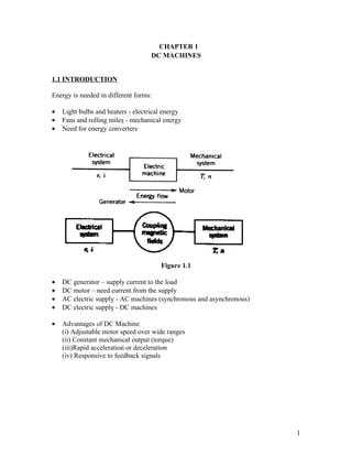
  • 1. CHAPTER 1 DC MACHINES 1.1 INTRODUCTION Energy is needed in different forms: • Light bulbs and heaters - electrical energy • Fans and rolling miles - mechanical energy • Need for energy converters Figure 1.1 • DC generator – supply current to the load • DC motor – need current from the supply • AC electric supply - AC machines (synchronous and asynchronous) • DC electric supply - DC machines • Advantages of DC Machine (i) Adjustable motor speed over wide ranges (ii) Constant mechanical output (torque) (iii)Rapid acceleration or deceleration (iv) Responsive to feedback signals 1
  • 2. Figure 1.2 : DC machine Construction 1.2 GENERATION OF AC SIGNAL • Generator needs something to rotate or move itself. • It is called the prime mover. • The shaft of the prime mover will be coupled to the shaft of the generator so that the generator can rotate once the prime mover rotates. • In a big system, they normally used 3-phase induction motor. • But, in small scale machine, they can use a mechanism to rotate the generator which then generated electricity. coil Slip ring:used to generate ac signal Carbon brush: used to collect output voltage (ac signal) carbon brush Figure 1.3: Physical Arrangement of AC Generating Method 2
  • 3. Figure 1.4 : Emf generated at various instant (angle position) 1.3 GENERATION OF DC SIGNAL • The generating of DC signal can be done by replacing the slip ring with commutator so that rectification process can happen. • Commutator can generate dc signal. • This is done through rectification or commutation process; which converts ac signal into dc mechanically. • Therefore a commutator is called a mechanical rectifier. Carbon commutator:used to brush generate dc signal Carbon brush: used to collect output voltage (dc signal) commutator Figure 1.5 : Physical Arrangement of DC Generating Method 3
  • 4. Figure 1.6: AC is converted into DC Signal through Commutation Process 1.4 EMF GENERATED ON DC MACHINE The EMF generated:- zNP EMF = 2 φ c60 where z = no of conductors in the armature circuit c = no. of parallel path N = speed in rpm Φ = flux/pole (Wb) P = no. of pole pair Figure 1.7 : Permanent Magnet Dc Machine 4
  • 5. Example 1 If the no-load voltage of a separately excited generator is 135 V at 850 rpm, what will be the voltage if the speed is increased to 1000 rpm? Assume constant field excitation. Solution 2 zPNφ EMF = c60 2 zP K= c60 Therefor , E1 = KN 1φ1 E 2 = KN 2φ 2 Constant field excitation:- i1 = i2 , ⇒ φ1 = φ 2 E1 KN 1φ1 N = = 1 E 2 KN 2φ 2 N 2 E1 N 2 1000rpm(135V ) E2 = = = 158.8V N1 850rpm Example 2 A separately excited generator has no-load voltage of 140 V when the field current is adjusted to 2 A. The speed is 900 rpm. Assume a linear relationship between the field flux and current. Calculate: (i) the generated voltage when the field current is increased to 2.5 A. Assume N1=N2. (ii) the terminal voltage when the speed is increased to 1000 rpm with the field current set at 2.2 A. Solution V1 = 140V , I F 1 = 2 A, N 1 = 900rpm φαI F (i) I F 2 = 2.5 A E1 KN 1φ1 I = = F1 E 2 KN 2φ 2 I F 2 E1 I F 2 140(2.5) E2 = = = 175V I F1 2 (ii) N 2 = 1000rpm, I F 2 = 2.2 A, V2 = ? 5
  • 6. E1 KN 1φ1 NI = = 1 F1 E 2 KN 2φ 2 N 2 I F 2 E1 N 1 I F 2 140(1000)(2.2) E2 = = = 171.11V N 2 I F1 (900)2 1.5 DC MACHINE CONSTRUCTION rotor/armature pole Figure 1.8 : DC Machine Construction DC motor principles • DC motors consist of rotor-mounted windings (armature) at the rotor side and stationary windings (field poles) at the stator side. 6
  • 7. In all DC motors, except permanent magnet motors, current must be conducted to the armature windings by passing current through carbon brushes that slide over a set of copper surfaces called a commutator, which is mounted on the rotor. • The commutator bars are soldered to armature coils. • The brush/commutator combination makes a sliding switch that energizes particular portions of the armature, based on the position of the rotor. • This process creates north and south magnetic poles on the rotor that are attracted to or repelled by north and south poles on the stator, which are formed by passing direct current through the field windings. • It's this magnetic attraction and repulsion that causes the rotor to rotate. Figure 1.9 : DC Machine Construction 1.6 MACHINE WINDINGS • Machine winding can be divide into 2:- (i) armature winding (rotor side) (ii) field winding (stator side) 7
  • 8. Machine Winding Field winding Armature Winding Separately excited **Self excited -no direct connection -direct connection between between armature circuit armature circuit and the and the field circuit field circuit Series Compound Shunt excitation excitation excitation Figure 1.10: Winding Connection in DC Machine SELF-EXCITED FIELD WINDING • In self-excited dc machine, there are three types of excitation method namely: (i) Series Excitation: the field winding is connected in series with the armature circuit. (ii) Shunt Excitation: the field winding is connected in parallel with the armature circuit. (iii) Compound Excitation: the field winding are connected in series and parallel with the armature circuit. • The schematic diagrams for the three types of these machines are illustrated in Figure 1.11. • The difference between dc motor and dc generator is in terms of the current direction. • In dc generator: armature current, Ia is supplied by the armature. In dc motor: armature current, Ia is received by the armature. 8
  • 9. (a) DC Series machine Rf Rf IL IL Ra Ra dc supply DC loa d Ia VT Ia VT 1.0 k 1.0 k 1.0m 1.0m 5.0 + + Eg EC - - Generator: Eg = VT + Ia(Ra + Rf) Motor: Ec = VT - Ia(Ra + Rf) (b)DC Shunt machine IL If IL If Ra Ra DC loa d 1.0 k dc supply 1.0 k 1.0 m 1.0 m Ia Rf VT 5.0 Ia Rf + VT + Eg Ec - - Generator: Eg = VT + IaRa Motor: Ec = VT - IaRa (c) DC Compound machine Rf2 Rf2 IL IF IL Ra IF Ra Ia D Cload Ia Rf1 VT Rf1 dc supply 1,0m 1,0 1,0m DCM1 1,0m + VT + Eg Ec D CM1 - 1,0m 1,0m - Generator: Eg = VT + Ia(Ra + Rf 2) Motor: Ec = VT - Ia(Ra + Rf 2) Figure 1.11 ** Eg = generated emf Ec = counter emf 9
  • 10. 1.7 POWER FLOW DIAGRAM Power flow diagram is normally represented as a fish bone. Input Power = Output + Losses Losses can be divided into 2:- (i) Copper losses (Armature copper loss , Pca) and (Field copper loss,Pcf) (ii) Iron losses, Pµ (friction, stray, windage,mechanical losses) For DC Generator: Pin = Pout + Total losses where Pout = VTIL For DC Motor: Pin = Pout + Total losses where Pin = VTIL Total losses = Pca + Pcf + Pµ 10
  • 11. POWER FLOW DIAGRAM FOR DC GENERATOR DC SERIES Pµ Pcf Pin Pout= VTIL Pca DC SHUNT Pµ Pcf Pin Pout= VTIL Pca DC COMPOUND Pµ Pcf1 Pin Pout= VTIL Pca Pcf2 11
  • 12. POWER FLOW DIAGRAM FOR DC MOTOR DC SERIES Pca Pµ Pm Pout Pin=VTIL Pcf DC SHUNT Pca Pµ Pm Pin=VTIL Pout Pcf DC COMPOUND Pca Pcf2 Pin = VTIL Pm Pout Pµ Pcf1 1.8 MOTOR TORQUE For load torque@shaft torque@net torque@output torque: 60 Pout To = 2πN For mechanical torque: 60 Pm Tm = 2πN For loss torque: 60 Pµ TL = 2πN 12
  • 13. 1.9 EFFICIENCY Generally efficiency is: Pout η= Pin For dc generator: Pout VTIL η= = Pin VTIL + Losses For dc motor: Pout Pm − Pµ η= = Pin VTIL Example 3 A short-shunt compound generator delivers 50 A at 500 V to a resistive load. The armature, series field and shunt field resistances are 0.16, 0.08 and 200 Ω, respectively. Calculate the generated EMF and armature current, if the rotational losses are 520 W, determine the efficiency of the generator. Solution 0.08 ohm IF IL 50 A 0.16 ohm load D CM1 1,0m 200 ohm 1,0m 500V 1,0m - Eg + Pµ = 520W Pout = VI = 500(50) = 25000W 13
  • 14. 500V IF = = 2.5 A 200Ω I a = I F + I L = 2.5 + 50 = 52.5 A E g = VT + I a ( Ra + R f ) E g = 500 + (52.5)(0.08 + 0.16) = 512.6V Pin = Pout + Ploss Ploss = Pca + Pcf + Pµ = (52.5 2 )(0.16) + (52.5 2 )(0.08) + (2.5 2 )(200) + 520 = 2431.5W Pout 25000 η= = x100% = 91.13% Pin 25000 + 2431.5 Example 4 A 150 V shunt motor has the following parameters: Ra = 0.5 Ω, Rf = 150 Ω and rotational loss 250 W. On full load the line current is 19.5 A and the motor runs at 1400 rpm. Determine: (i) the developed power/developed mechanical power (ii) the output power (iii) the output torque (iv) the efficiency at full load Solution IL = 19.5A N = 1400rpm (i) Pm = E c I a Ia = IL − IF I L = 19.5 A VT 150 IF = = =1 R F 150 I a = 19.5 − 1 = 18.5 A E c = VT − I a Ra = 150 − 18.5(0.5) = 140.75V Pm = E c I a = (140.75)(18.5) = 2603.88W 14
  • 15. OR :- Pm = Pin − Pca − Pcf Pm = VT I L − I a Ra − I F RF 2 2 Pm = 150(19.5) − (18.5 2 )(0.5) − (12 )(150) = 2603.88W (ii) Pout = Pm − Pµ = 2603.88 − 250 = 2353.88W 60 Pout 60(2353.88) (iii) To = = = 16.06 Nm 2πN 2π (1400) Pout P 2353.88 (iv) η= = out = = 80.47% Pin VT I L 150(19.5) 15
  • 16. Tutorial 1 1. A 300 V compound motor has armature resistance 0.18 Ω, series field resistance 0.3 Ω and shunt field resistance 100 Ω. The rotational losses are 200 W. On full load the line current is 25 A and the motor runs at 1800 rpm. Determine: (i) the developed mechanical power (ii) the output power (iii) the output torque (iv) the efficiency at full load 2. A 120 V series motor has 0.2 Ω field resistance. On full load, the line current is 16.5 A. The output power is 1500 W and rotational loss is 150 W. Find the value of armature resistance. 3. Briefly explain the difference between motor and generator of DC machine. 4. A compound DC motor rated at 415 V, 6 HP, 2000 rpm has armature resistance 0.18 Ω, series field resistance 0.3 Ω and shunt field resistance 100 Ω. The rotational losses are 200 W. The full load line current is 40 A. (i) Find the developed mechanical power. (ii) Find the output power. (iii) Find the load torque. (iv) Find the efficiency of the motor. (v) Draw the power flow diagram for this type of motor. 5. A DC series generator delivers 100 kW at 10 kV to a load. The armature resistance is 20 Ω and the field resistance is 50 Ω. Calculate: (i) the generated emf, Eg (ii) the input power if the stray and friction losses are 400 W. 16