Burkert 6013 - 2/2 Solenoid Valve > นิวเมติก.com
•
0 recomendaciones•1,074 vistas

ตัวแทนจำหน่าย Burkert 6013 และ Burkert 6013A ติดต่อ บริษัท นิวเมติก ดอทคอม (ประเทศไทย) จำกัด www.นิวเมติก.com
![6013
Technical data, continued
Circuit function A
Orifice Port
Kv-value Weight
connection water
[mm]
[m3/h]
[g]
Power consumption
2.0
G1/8
0.12
2.0
G1/4
0.12
2.0
sub-base
2.5
1)
Electr. power
[W]
Inrush
(AC)
325
8W AC or 8W DC (9)
24 VA
17 VA
465
8W AC or 8W DC (9)
24 VA
17 VA
0.12
290
8W AC or 8W DC (9)
24 VA
G1/8
0.16
325
8W AC or 8W DC (9)
2.5
G1/4
0.16
465
3.0
G1/8
0.23
3.0
G1/4
3.0
Coil size
Hold
(AC)
Response times
opening
[ms]
closed
[ms]
5 (32mm)
20
30
5 (32mm)
20
30
17 VA
5 (32mm)
20
30
24 VA
17 VA
5 (32mm)
20
30
8W AC or 8W DC (9)
24 VA
17 VA
5 (32mm)
20
30
325
8W AC or 8W DC (9)
24 VA
17 VA
5 (32mm)
20
30
0.23
465
8W AC or 8W DC (9)
24 VA
17 VA
5 (32mm)
20
30
G3/8
0.23
550
10W AC or 10WDC (11)
30 VA
22 VA
6 (40mm)
20
30
4.0
G1/4
0.30
465
8W AC or 8W DC (9)
24 VA
17 VA
5 (32mm)
20
30
4.0
G3/8
0.30
550
10W AC or 10WDC (11)
30 VA
22 VA
6 (40mm)
20
30
6.0
G1/4
0.55
465
8W AC or 8W DC (9)
24 VA
17 VA
5 (32mm)
20
30
6.0
G3/8
0.55
550
10W AC or 10WDC (11)
30 VA
22 VA
6 (40mm)
20
30
Circuit function B
Orifice
Weight
[mm]
Port
Kv-value
connection water
[m3/h]
[g]
2.00
G 1/8
0.12
2.00
G 1/4
0.12
2.00
sub-base
3.00
3.00
Power consumption
1)
Electr. power
[W]
Inrush
(AC)
325
7 W(AC) or 8 W DC (9)
24VA
17VA
465
7 W(AC) or 8 W DC (9)
24VA
17VA
0.12
290
7 W(AC) or 8 W DC (9)
24VA
G 1/8
0.23
325
7 W(AC) or 8 W DC (9)
G 1/4
0.23
465
7 W(AC) or 8 W DC (9)
3.00
sub-base
0.23
290
4.00
G 1/4
0.3
6.00
G 1/4
0.55
Coil size
Hold
(AC)
1)
Response times
opening
[ms]
closed
[ms]
5 (32mm)
20
30
5 (32mm)
20
30
17VA
5 (32mm)
20
30
24VA
17VA
5 (32mm)
20
30
24VA
17VA
5 (32mm)
20
30
7 W(AC) or 8 W DC (9)
24VA
17VA
5 (32mm)
20
30
465
7 W(AC) or 8 W DC (9)
24VA
17VA
5 (32mm)
20
30
465
7 W(AC) or 8 W DC (9)
24VA
17VA
5 (32mm)
20
30
Values in brackets at coil temperature 20ºC
Materials
Locknut:
Stainless steel
(surface finish
thick film passivated)
(Brass version)
Stainless st. 1.4305 PTFE
(stainless steel version)
Cable plug: PA (polyamide)
Stopper:
Shading ring:
1.4105
Cu (brass version)
AG (stainless steel version)
Flat seal:
NBR
Spring:
1.4310
Coil:
PA (polyamide)
Epoxy (high temperature
version
Magnetic core:
1.4105
Cover:
Polyamide
Armature guide tube:
St. st. (surface
thick film passivated)
Stainless steel 1.4301
Seal:
Sub-base:
1.4303
FKM
(Graphite high temp. Version)
Armature seal:
FKM
(PTFE high temp. Version)
Valve body:
Brass
Stainless steel 1.4305
p. 2/9](data:image/gif;base64,R0lGODlhAQABAIAAAAAAAP///yH5BAEAAAAALAAAAAABAAEAAAIBRAA7)
Recomendados
Recomendados
Más contenido relacionado
La actualidad más candente
La actualidad más candente (18)
Similar a Burkert 6013 - 2/2 Solenoid Valve > นิวเมติก.com
Similar a Burkert 6013 - 2/2 Solenoid Valve > นิวเมติก.com (20)
Más de DNTMb Inc.
Más de DNTMb Inc. (20)
Último
Último (20)
Burkert 6013 - 2/2 Solenoid Valve > นิวเมติก.com
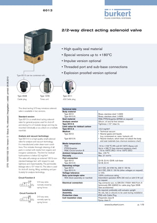
- 1. 6013 2/2-way direct acting solenoid valve • High quality seal material • Special versions up to +180ºC • Impulse version optional • Threaded port and sub-base connections Type 6013 can be combined with… • Explosion proofed version optional Type 2508 Type 1078 Type 2511 Cable plug Timer unit ASI Cable plug This direct-acting 2/2-way miniature solenoid valve is available in two versions. Standard version: Type 6013 is a small direct acting solenoid valve for general purpose used for shut-off and dosing. It is of modular design and may be mounted individually or as a block on a multiple manifold. Analysis and vacuum technology: Type 6013 A is a high-quality small solenoid valve for analysis and vacuum technology. It is manufactured under clean-room conditions. This includes thorough cleaning of all parts in contact with media from organic and inorganic substances. The limit for residual hydrocarbons is below 0.2 mg/dm². The valve will undergo an external 100 % nonstandard leakage test with respect to seat tightness and impermeability. The permissible leakage rate is 10-4 mbar l/s. The valve is used for shut-off, dosing, filling, ventilating and particularly for analysis technology. Circuit Function A 2/2-way valve, normally closed by spring fornce Circuit Function B 2/2-way valve, normally open by spring fornce Technical data Body material Type 6013 Type 6013 A Seal material Analysis version Type 6013 A Limit value for risidual carbon Type 6013 A Medium Type 6013 Brass, stainless steel 1.4305 Brass, stainless steel 1.4305 FKM, PTFE/Graphite (EPDM on request) Silicon, oil and fat free version Tightness <10-4 mbar l/s <0.2 mg/dm² • Technical vacuum • Neutral gases and liquids (e.g. compressed air, water, hydraulic oil) Type 6013 A Media temperature FKM PTFE/Graphite FKM, Circuit function B Ambient temperature Viscosity Port connection Type 6013 Type 6013 A Operating voltage Type 6013 Type 6013 A Voltage tolerance Duty cycle/single valve With block assembly on manifold Electrical connection Installation Assembly Protection class Coil insulation class • Neutral medium, which does not attack the body and seal materials (see chemical resistance chart) -10 to +100 °C (PA coil) till 120ºC (Epoxy coil) Up to +180 ºC (see chemical resistance chart) -10 to 100°C (AC) -10 to 120°C (DC) Max. +55 °C Max. 21 mm²/s G1/8, G1/4, G3/8, sub-base G1/8, G1/4 24 V DC, 24 V/50 Hz, 230 V / 50 Hz 24 V DC, 230 V / 50 Hz (other voltages on request) ± 10% 100% continuous rating Intermittent operation 60% (30 min) or with 5 W coil on request Tag connector acc. to DIN EN 175301-803 Form A (previously DIN 43650) for cable plug Type 2508 (see accessories) As required, preferably with actuator upright No oils, fats or silicone to be used during installation IP65 with Cable Plug Polyamide class B Epoxy class H www.burkert.com p. 1/9
- 2. 6013 Technical data, continued Circuit function A Orifice Port Kv-value Weight connection water [mm] [m3/h] [g] Power consumption 2.0 G1/8 0.12 2.0 G1/4 0.12 2.0 sub-base 2.5 1) Electr. power [W] Inrush (AC) 325 8W AC or 8W DC (9) 24 VA 17 VA 465 8W AC or 8W DC (9) 24 VA 17 VA 0.12 290 8W AC or 8W DC (9) 24 VA G1/8 0.16 325 8W AC or 8W DC (9) 2.5 G1/4 0.16 465 3.0 G1/8 0.23 3.0 G1/4 3.0 Coil size Hold (AC) Response times opening [ms] closed [ms] 5 (32mm) 20 30 5 (32mm) 20 30 17 VA 5 (32mm) 20 30 24 VA 17 VA 5 (32mm) 20 30 8W AC or 8W DC (9) 24 VA 17 VA 5 (32mm) 20 30 325 8W AC or 8W DC (9) 24 VA 17 VA 5 (32mm) 20 30 0.23 465 8W AC or 8W DC (9) 24 VA 17 VA 5 (32mm) 20 30 G3/8 0.23 550 10W AC or 10WDC (11) 30 VA 22 VA 6 (40mm) 20 30 4.0 G1/4 0.30 465 8W AC or 8W DC (9) 24 VA 17 VA 5 (32mm) 20 30 4.0 G3/8 0.30 550 10W AC or 10WDC (11) 30 VA 22 VA 6 (40mm) 20 30 6.0 G1/4 0.55 465 8W AC or 8W DC (9) 24 VA 17 VA 5 (32mm) 20 30 6.0 G3/8 0.55 550 10W AC or 10WDC (11) 30 VA 22 VA 6 (40mm) 20 30 Circuit function B Orifice Weight [mm] Port Kv-value connection water [m3/h] [g] 2.00 G 1/8 0.12 2.00 G 1/4 0.12 2.00 sub-base 3.00 3.00 Power consumption 1) Electr. power [W] Inrush (AC) 325 7 W(AC) or 8 W DC (9) 24VA 17VA 465 7 W(AC) or 8 W DC (9) 24VA 17VA 0.12 290 7 W(AC) or 8 W DC (9) 24VA G 1/8 0.23 325 7 W(AC) or 8 W DC (9) G 1/4 0.23 465 7 W(AC) or 8 W DC (9) 3.00 sub-base 0.23 290 4.00 G 1/4 0.3 6.00 G 1/4 0.55 Coil size Hold (AC) 1) Response times opening [ms] closed [ms] 5 (32mm) 20 30 5 (32mm) 20 30 17VA 5 (32mm) 20 30 24VA 17VA 5 (32mm) 20 30 24VA 17VA 5 (32mm) 20 30 7 W(AC) or 8 W DC (9) 24VA 17VA 5 (32mm) 20 30 465 7 W(AC) or 8 W DC (9) 24VA 17VA 5 (32mm) 20 30 465 7 W(AC) or 8 W DC (9) 24VA 17VA 5 (32mm) 20 30 Values in brackets at coil temperature 20ºC Materials Locknut: Stainless steel (surface finish thick film passivated) (Brass version) Stainless st. 1.4305 PTFE (stainless steel version) Cable plug: PA (polyamide) Stopper: Shading ring: 1.4105 Cu (brass version) AG (stainless steel version) Flat seal: NBR Spring: 1.4310 Coil: PA (polyamide) Epoxy (high temperature version Magnetic core: 1.4105 Cover: Polyamide Armature guide tube: St. st. (surface thick film passivated) Stainless steel 1.4301 Seal: Sub-base: 1.4303 FKM (Graphite high temp. Version) Armature seal: FKM (PTFE high temp. Version) Valve body: Brass Stainless steel 1.4305 p. 2/9
- 3. 6013 Ordering chart for valves (other versions on request) 6013 Universal valve with FKM seal, brass and stainless steel body (Polyamide coil) Orifice [mm] Port connection Kv value water [m³/h] 1) Coil power [W] A 2/2-way valve NC 2.0 G 1/8 0.12 8 8 Item no. Stainless steel body, FKM seal Voltage/ Frequency [V/Hz] 0.23 137 534 230/50 137 540 137 536 0 - 12 024/DC 134 244 – 024/50 134 245 – 230/50 134 247 – 0 - 10 024/DC 134 240 – 024/50 134 241 – 230/50 134 243 – 0-6 024/DC 126 091 126 078 024/50 126 092 126 079 230/50 126 094 126 081 0-6 024/DC 125 301 125 317 0 - 10 G 1/4 8 137 538 0 - 10 0.23 8 137 533 024/50 0 - 10 G 1/8 0.16 134 236 137 537 0 - 16 3.0 G 1/8 134 239 024/DC 0 - 16 2.5 230/50 0 - 12 0 - 25 8 134 234 0 - 25 0.12 134 233 132 865 0 - 25 sub-base 134 237 024/50 0 - 25 8 024/DC 0 - 25 0.12 0 - 12 0 - 25 G 1/4 Pressure range [bar] Item no. brass body FKM Seal 2) Circuit function Delivered without cable plug (see accessories) 024/50 125 302 126 082 126 084 0 - 10 G 1/4 0.30 8 230/50 125 304 0 - 1.5 024/DC 125 306 125 318 0-4 4.0 024/50 125 307 125 319 125 320 0-4 1) 2) 0.55 8 230/50 125 309 024/DC 125 311 126 086 024/50 125 312 126 087 0 - 1.5 G 1/4 0 - 0.5 0 - 1.5 6.0 230/50 125 314 126 089 Measured at +20 °C, 1 bar2) pressure at valve inlet and free outlet.. Measured as overpressure to the atmospheric pressure Ordering chart for valves 6013 Universal valve with FKM seal, brass body (Epoxy coil) 0.12 0 - 16 G1/8 0.23 0-8 3.0 G1/4 4.0 6.0 G1/4 G1/4 0.23 0.3 0.55 0-8 0-4 0-2 Item no.. Pressure range [bar] 2) G1/8 Voltage/ Frequency [V/Hz] Kv value water [m³/h] 1) 2.0 Coil power [W] Port connection B 2/2-way valve NO Orifice [mm] Circuit function Delivered without cable plug (see accessories) 8 24/DC 213 543 7 230/50 213 550 8 24/DC 213 545 7 230/50 213 551 8 24/DC 213 546 7 230/50 213 552 8 024/DC 213 548 7 230/50 213 553 8 024/DC 213 549 7 230/50 213 554 1) Measured at +20 °C, 1 bar2) pressure at valve inlet and free outlet.. 2) Measured as overpressure to the atmospheric pressure p. 3/9
- 4. 6013 Ordering chart for valves 6013 Universal valve with FKM seal, G 3/8, brass body (polyamide coil) Port connection Kv value water [m³/h] 1) Coil power [W] 3.0 G 3/8 0.23 10 024/DC 134 248 135 430 024/50 134 249 135 431 Item no. Stainless steel seat, FKM Seal 0–8 0 – 14 Item no. brass seat, FKM Seal Voltage/ Frequency [V/Hz] Orifice [mm] A 2/2-way valve NC Pressure range [bar] 2) Circuit function Delivered without cable plug (see accessories) 0 – 14 1) 2) 0.55 135 433 134 252 135 434 024/50 134 253 135 435 230/50 134 255 135 437 0 – 0.75 10 134 251 024/DC 134 256 135 438 024/50 134 257 135 439 0 – 2.5 G 3/8 10 230/50 0 – 2.5 6.0 0.30 024/DC 0–6 G 3/8 0 – 2.5 0–6 4.0 230/50 134 259 135 441 Measured at +20 °C, 1 bar2) pressure at valve inlet and free outlet.. Measured as overpressure to the atmospheric pressure Ordering chart for valves 6013 Valves for high temperature applications (to ±180ºC), PTFE seat seal, brass body Kv value water [m³/h] 1) Coil power [W] 0.23 10 P G 3/8 1) 2) 0.23 10 230/50 136 018 0–6 024/DC 136 019 024/50 136 020 230/50 136 022 0–8 024/DC 136 023 024/50 136 024 230/50 136 026 Item no. Port connection G 1/4 Voltage/ Frequency [V/Hz] Orifice [mm] 3.0 136 015 0 – 14 8 136 016 0 – 14 0.12 024/50 0 – 10 G 1/4 024/DC 0 – 10 2.0 0 – 12 0 – 25 0 – 25 A 2/2-way valve NC A Pressure range [bar] 2) Circuit function Delivered without cable plug (see accessories) Brass body with Stainless steel seat (Epoxy coil) 2) Measured at +20 °C, 1 bar pressure at valve inlet and free outlet. Measured as overpressure to the atmospheric pressure. p. 4/9
- 5. 6013 Ordering chart for valves, Standard temperature version for DC power supply, impulse version All valves with 32mm coil(AC10), Impulse version, seal material FKM,thermal Insulation class H (epoxy coil), medium temperature -10°C to 120°C, without manual override and cable plug Power consumption DC (hot/cold coil) [W] 012/DC 024/DC 209 266 209 272 0.16 0-10 7 209 267 209 273 0.23 0-6 7 209 268 209 274 2.0 0.12 0-16 7 209 269 209 275 2.5 0.16 0-10 7 209 270 209 276 3.0 0.23 0-6 7 209 271 209 277 2) Pressure range [bar] 7 3.0 Circuit function 0-16 2.5 Sub-base G 1/8 2) 0.12 Brass body A 2/2-way valve 1) Kv-value water [m3/h] 1) 2.0 Port connection Orifice [mm] Item no. per voltage/ frequency [V/Hz] 2) Measured at +20 °C, 1 bar pressure at valve inlet and free outlet.. Measured as overpressure to the atmospheric pressure Please note that the cable plug must be ordered separately, see accessories on page 8 and separate datasheet, Type 2508. Control for impulse version with polarity reversal control Polarity is marked on the coil with a label Features Terminal connections - switch ON + valve (P-seat) open (+) on terminal 2 and (-) on terminal 1 (see below) + switch OFF - valve (P-seat) closed (+) on terminal 1 and (-) on terminal 2 (see below) Protective conductor port 2 1 Polarity is marked on the coil with a label – switch ON + + switch OFF + port valve coil connection Pulse duration at least 50 ms. Note: Please use only the cable plug without electrical circuitry for the impulse version p. 5/9
- 6. 6013 Technical data - analytical version Analysis version Media flowing through are not contaminated Limit for risidual carbon <0.2 mg/dm² Permissible leakage rate for medium 10-4 mbar l/sec • Neutral medium, which does not attack the body and seal materials • Technical vacuum Electr. connection Tag connector acc. to DIN EN 175301-803 Form A (previously DIN43650) for cable plug Type 2508 (see accessories) No oils, fats or silicone used during the assembly Mounting instructions Solenoid valves for higher Requirements This version is particularly suitable for switching from extremely pure gaseous medium. All media-affected parts are submitted to additional purification processes, so that the media is not contaminated under any circumstances. The assembly takes place under clean-room conditions. The tightness test takes place at the Helium leak detector from a min. of 10-4 mbar I/sec. Ordering chart for valves (other versions on request) 6013A Analytical valve with brass body and FKM seal, (Polyamide coil) Kv value water [m³/h] 1) Pressure range [bar] 2) Coil power [W] 2.0 G 1/8 0.12 0-12 8 2.5 G1/8 0.16 0-10 3.0 P G 1/4 0.23 0-6 0-10 4.0 G 1/4 0.30 0-1.5 8 0-4 1) 2) 137 828 137 829 24/DC 137 830 137 831 24/DC 137 832 230/50 8 137 827 24/DC 230/50 0-16 137 826 230/50 8 24/DC 230/50 0-25 A Item no. Port connection A 2/2-way valve NC Voltage/ Frequency [V/Hz] Orifice [mm] Circuit function Delivered without cable plug (see accessories) 137 833 2) Measured at +20 °C, 1 bar pressure at valve inlet and free outlet.. Measured as overpressure to the atmospheric pressure 6013A Analytical valve with stainless steel body and FKM seal, (Polyamide coil) Kv value water [m³/h] 1) Pressure range [bar] 2) Coil power [W] 2.0 G 1/8 0.12 0-12 8 2.0 G1/4 0.12 0-12 P 3.0 G 1/4 0.23 0-6 8 0-10 4.0 G 1/4 0.30 0-1.5 0-4 8 137 819 24/DC 137 820 137 821 24/DC 137 822 230/50 0-25 137 818 230/50 8 24/DC 230/50 0-25 Item no. Port connection A 2/2-way valve NC A Voltage/ Frequency [V/Hz] Orifice [mm] Circuit function Delivered without cable plug (see accessories) 137 823 24/DC 137 824 230/50 137 825 1) Measured at +20 °C, 1 bar2) pressure at valve inlet and free outlet.. 2) Measured as overpressure to the atmospheric pressure Please note that the cable plug must be ordered separately, see accessories on page 8 and separate datasheet, Type 2508. p. 6/9
- 7. 6013 Dimensions [mm] View without cable plug Sub-base version underside view G3/8 connection Port connection Body dimensions [mm] A B C Coil width D Coil depth E [mm] G F [mm] G1/8 G1/8 32 20.8 32.6 8 32 (8W) G1/4 G1/4 46 26.8 49 12 32 (8W) 45 (8W) G3/8 G3/8 50 39.8 49 12 40 (10W) 51 (10W) – 32 14.3 32.6 – 32 (8W) 45 (8W) Sub-base 45 (8W) p. 7/9
- 8. 6013 Manifold mounting Single manifold Multiple manifold A C 16 33 33 B Single manifold Multiple manifold Connector nipple Covering plate in aluminium in aluminium Hole spacing A [mm] Total length B [mm] 2 57 65 3 90 98 4 123 131 5 156 164 6 189 197 8 255 263 10 321 329 with O-Ring, to connect from manifold with screws and O-ring for locking unoccupied valve positions Item no. Quantity of valve places Accessory part Ordering chart for Manifolds 005 020 Hole spacing C [mm] – – – 57 57 90 90 005 023 005 286 005 287 005 035 005 038 005 386 005 764 005 040 005 630 With manifold mounting, please comply with the permissible duty cycle (5W models with 100% continuous rating or 8W model with 60% duty cycle). The pressure port for the manifold is designated with P (R), and the outlet port with A (B). Only connect together ports with the same designation. 2/2-way valves of Type 6013 can be operated together on a manifold with 3/2-way valves of Type 6014, circuit function C (not D or T!) if the operating pressures agree according to the rating plates. The manifolds can also be expanded if the valve functions are taken into consideration. Connector nipples with O-rings are used to connect the P (R) ports. Attention! Unused, open valve ports must be closed off with covering plates (see accessories). Manifold should be fixed on to a rail. p. 8/9
- 9. 6013 Ordering chart for accessories Included in delivery is a cable plug with flat seal and fixing screw. Other versions with cable plug acc. to DIN EN 175301-803 (previously DIN43650), see Datasheet: Type 2508. Circuit 0 -250 V with LED 12 -24 V 008 360 with LED and varistor 12 -24 V 008 367 with LED and varistor 200 -240 V 008 369 with inverter 1) 24V DC further versions 1) Voltage without circuitry Item no. see datasheet Type 2508 008 376 on request Type 2508 Cable plug acc. to DIN EN 175301-803 (previously DIN 43650) The inverter plug contains an electronic, which especially enables the electric 3 wire control Input for 3 wire technology, common “-” polarity, two split “+” polarity. Output suitable for implulse version for Type 6013/6014 Further versions on request Approval Ex version UL / UR / CSA ATEX FM / CSA-EX Div 1/2 European gas approval Class A, Group 2 Port connection Threaded port NPT, Rc Voltage Further voltages Materials Seal material EPDM Pressure Variants with increased coil power for higher medium pressure To find your nearest Burkert facility, click on the orange box In case of special application conditions, please consult for advice.. www.burkert.com Subject to alterations © Christian Bürkert GmbH & Co. KG 1306/12_EU-en_00891729 p. 9/9