
Recomendados
Recomendados
Más contenido relacionado
Similar a C1fm5 125-rigging method
Similar a C1fm5 125-rigging method (20)
Último
Último (20)
C1fm5 125-rigging method
- 1. FM 5-125 C1 Change 1 Headquarters Department of the Army Washington, DC, 23 February 2001 Rigging Techniques, Procedures, and Applications 1. Change FM 5-125, 3 October 1995, as follows: Remove Old Pages Insert New Pages i through iv i through iv vii and viii vii and viii 1-15 through 1-20 1-15 through 1-21 2-37 through 2-40 2-37 through 2-40 2. A bar ( ) marks new or changed material. 3. File this transmittal sheet in front of the publication. DISTRIBUTION RESTRICTION: Approved for public release; distribution is unlimited. ERIC K. SHINSEKI General, United States Army Chief of Staff Official: JOEL B. HUDSON Adiministrative Assistant to the Secretary of the Army 0100405 DISTRIBUTION: Active Army, Army National Guard, and US Army Reserve: To be distributed in accordance with the initial distribution number 115426, requirements for FM 5-125.
- 2. *FM 5-125 Field Manual Headquarters No. 5-125 Department of the Army Washington, DC, 3 October 1995 Rigging Techniques, Procedures, and Applications Contents Page LIST OF FIGURES . . . . . . . . . . . . . . . . . . . . . . . . . . . . . . . . . . . . . . . . . . . . . . . . . . . . . vii LIST OF TABLES . . . . . . . . . . . . . . . . . . . . . . . . . . . . . . . . . . . . . . . . . . . . . . . . . . . . . . xv PREFACE . . . . . . . . . . . . . . . . . . . . . . . . . . . . . . . . . . . . . . . . . . . . . . . . . . . . . . . . . . . . xvii Chapter 1. Rope Section I. Fiber Rope . . . . . . . . . . . . . . . . . . . . . . . . . . . . . . . . . . . . . . . . . . . . . . . . 1-1 Types of Fibers . . . . . . . . . . . . . . . . . . . . . . . . . . . . . . . . . . . . . . . . . . . . . . . . . . . . . 1-1 Vegetable Fibers. . . . . . . . . . . . . . . . . . . . . . . . . . . . . . . . . . . . . . . . . . . . . . . . . . 1-1 Synthetic Fibers . . . . . . . . . . . . . . . . . . . . . . . . . . . . . . . . . . . . . . . . . . . . . . . . . . 1-3 Characteristics of Fiber Rope . . . . . . . . . . . . . . . . . . . . . . . . . . . . . . . . . . . . . . . . . . 1-3 Size . . . . . . . . . . . . . . . . . . . . . . . . . . . . . . . . . . . . . . . . . . . . . . . . . . . . . . . . . . . . 1-3 Weight . . . . . . . . . . . . . . . . . . . . . . . . . . . . . . . . . . . . . . . . . . . . . . . . . . . . . . . . . . 1-3 Strength . . . . . . . . . . . . . . . . . . . . . . . . . . . . . . . . . . . . . . . . . . . . . . . . . . . . . . . . 1-3 Care of Fiber Rope . . . . . . . . . . . . . . . . . . . . . . . . . . . . . . . . . . . . . . . . . . . . . . . . . . 1-4 Handling of Fiber Rope . . . . . . . . . . . . . . . . . . . . . . . . . . . . . . . . . . . . . . . . . . . . . . 1-5 Inspection of Fiber Rope . . . . . . . . . . . . . . . . . . . . . . . . . . . . . . . . . . . . . . . . . . . . . . 1-6 Section II. Wire Rope . . . . . . . . . . . . . . . . . . . . . . . . . . . . . . . . . . . . . . . . . . . . . . . . 1-6 Types of Wire-Rope Cores. . . . . . . . . . . . . . . . . . . . . . . . . . . . . . . . . . . . . . . . . . . . . 1-7 Fiber-Rope Cores . . . . . . . . . . . . . . . . . . . . . . . . . . . . . . . . . . . . . . . . . . . . . . . . . 1-7 Independent Wire-Rope Cores . . . . . . . . . . . . . . . . . . . . . . . . . . . . . . . . . . . . . . . 1-7 Wire-Strand Cores . . . . . . . . . . . . . . . . . . . . . . . . . . . . . . . . . . . . . . . . . . . . . . . . 1-7 DISTRIBUTION RESTRICTION: Approved for public release; distribution is unlimited. *This manual supersedes TM 5-725, 3 October 1968. i
- 3. C1, FM 5-125 FM 5-125 Page Classification of Wire Rope . . . . . . . . . . . . . . . . . . . . . . . . . . . . . . . . . . . . . . . . . . . 1-7 Wire and Strand Combinations . . . . . . . . . . . . . . . . . . . . . . . . . . . . . . . . . . . . . 1-7 Lay . . . . . . . . . . . . . . . . . . . . . . . . . . . . . . . . . . . . . . . . . . . . . . . . . . . . . . . . . . . . 1-7 Characteristics of Wire Rope . . . . . . . . . . . . . . . . . . . . . . . . . . . . . . . . . . . . . . . . . . 1-9 Size . . . . . . . . . . . . . . . . . . . . . . . . . . . . . . . . . . . . . . . . . . . . . . . . . . . . . . . . . . . . 1-9 Weight . . . . . . . . . . . . . . . . . . . . . . . . . . . . . . . . . . . . . . . . . . . . . . . . . . . . . . . . . 1-9 Strength . . . . . . . . . . . . . . . . . . . . . . . . . . . . . . . . . . . . . . . . . . . . . . . . . . . . . . . . 1-9 Care of Wire Rope. . . . . . . . . . . . . . . . . . . . . . . . . . . . . . . . . . . . . . . . . . . . . . . . . . 1-10 Reversing or Cutting Back Ends. . . . . . . . . . . . . . . . . . . . . . . . . . . . . . . . . . . . 1-11 Cleaning . . . . . . . . . . . . . . . . . . . . . . . . . . . . . . . . . . . . . . . . . . . . . . . . . . . . . . . 1-11 Lubricating. . . . . . . . . . . . . . . . . . . . . . . . . . . . . . . . . . . . . . . . . . . . . . . . . . . . . 1-11 Storing . . . . . . . . . . . . . . . . . . . . . . . . . . . . . . . . . . . . . . . . . . . . . . . . . . . . . . . . 1-11 Handling of Wire Rope . . . . . . . . . . . . . . . . . . . . . . . . . . . . . . . . . . . . . . . . . . . . . . 1-11 Kinking . . . . . . . . . . . . . . . . . . . . . . . . . . . . . . . . . . . . . . . . . . . . . . . . . . . . . . . . 1-12 Coiling . . . . . . . . . . . . . . . . . . . . . . . . . . . . . . . . . . . . . . . . . . . . . . . . . . . . . . . . 1-12 Unreeling . . . . . . . . . . . . . . . . . . . . . . . . . . . . . . . . . . . . . . . . . . . . . . . . . . . . . . 1-12 Seizing . . . . . . . . . . . . . . . . . . . . . . . . . . . . . . . . . . . . . . . . . . . . . . . . . . . . . . . . 1-12 Welding. . . . . . . . . . . . . . . . . . . . . . . . . . . . . . . . . . . . . . . . . . . . . . . . . . . . . . . . 1-14 Cutting . . . . . . . . . . . . . . . . . . . . . . . . . . . . . . . . . . . . . . . . . . . . . . . . . . . . . . . . 1-14 Drums and Sheaves . . . . . . . . . . . . . . . . . . . . . . . . . . . . . . . . . . . . . . . . . . . . . . 1-15 Inspection of Wire Rope . . . . . . . . . . . . . . . . . . . . . . . . . . . . . . . . . . . . . . . . . . . . . 1-20 Procedures . . . . . . . . . . . . . . . . . . . . . . . . . . . . . . . . . . . . . . . . . . . . . . . . . . . . . 1-20 Causes of Failure . . . . . . . . . . . . . . . . . . . . . . . . . . . . . . . . . . . . . . . . . . . . . . . . 1-21 Chapter 2. Knots, Splices, Attachments, and Ladders Section I. Knots, Hitches, and Lashings . . . . . . . . . . . . . . . . . . . . . . . . . . . . . . . 2-1 Knots . . . . . . . . . . . . . . . . . . . . . . . . . . . . . . . . . . . . . . . . . . . . . . . . . . . . . . . . . . . . . 2-2 Knots at the End of Rope. . . . . . . . . . . . . . . . . . . . . . . . . . . . . . . . . . . . . . . . . . . 2-4 Knots for Joining Two Ropes. . . . . . . . . . . . . . . . . . . . . . . . . . . . . . . . . . . . . . . . 2-5 Knots for Making Loops . . . . . . . . . . . . . . . . . . . . . . . . . . . . . . . . . . . . . . . . . . . 2-6 Knots for Tightening a Rope . . . . . . . . . . . . . . . . . . . . . . . . . . . . . . . . . . . . . . . 2-12 Knots for Wire Rope. . . . . . . . . . . . . . . . . . . . . . . . . . . . . . . . . . . . . . . . . . . . . . 2-13 Hitches . . . . . . . . . . . . . . . . . . . . . . . . . . . . . . . . . . . . . . . . . . . . . . . . . . . . . . . . . . 2-17 Half Hitch. . . . . . . . . . . . . . . . . . . . . . . . . . . . . . . . . . . . . . . . . . . . . . . . . . . . . . 2-17 Two Half Hitches . . . . . . . . . . . . . . . . . . . . . . . . . . . . . . . . . . . . . . . . . . . . . . . . 2-17 Round Turn and Two Half Hitches. . . . . . . . . . . . . . . . . . . . . . . . . . . . . . . . . . 2-18 Timber Hitch . . . . . . . . . . . . . . . . . . . . . . . . . . . . . . . . . . . . . . . . . . . . . . . . . . . 2-18 Timber Hitch and Half Hitch . . . . . . . . . . . . . . . . . . . . . . . . . . . . . . . . . . . . . . 2-18 Clove Hitch. . . . . . . . . . . . . . . . . . . . . . . . . . . . . . . . . . . . . . . . . . . . . . . . . . . . . 2-18 ii
- 4. C1, FM 5-125 FM 5-125 Page Rolling Hitch . . . . . . . . . . . . . . . . . . . . . . . . . . . . . . . . . . . . . . . . . . . . . . . . . . . 2-18 Telegraph Hitch . . . . . . . . . . . . . . . . . . . . . . . . . . . . . . . . . . . . . . . . . . . . . . . . . 2-19 Mooring Hitch . . . . . . . . . . . . . . . . . . . . . . . . . . . . . . . . . . . . . . . . . . . . . . . . . . 2-19 Scaffold Hitch . . . . . . . . . . . . . . . . . . . . . . . . . . . . . . . . . . . . . . . . . . . . . . . . . . . 2-19 Blackwall Hitch . . . . . . . . . . . . . . . . . . . . . . . . . . . . . . . . . . . . . . . . . . . . . . . . . 2-19 Harness Hitch . . . . . . . . . . . . . . . . . . . . . . . . . . . . . . . . . . . . . . . . . . . . . . . . . . 2-22 Girth Hitch . . . . . . . . . . . . . . . . . . . . . . . . . . . . . . . . . . . . . . . . . . . . . . . . . . . . . 2-22 Sheepshank . . . . . . . . . . . . . . . . . . . . . . . . . . . . . . . . . . . . . . . . . . . . . . . . . . . . 2-23 Fisherman's Bend . . . . . . . . . . . . . . . . . . . . . . . . . . . . . . . . . . . . . . . . . . . . . . . 2-23 Lashings . . . . . . . . . . . . . . . . . . . . . . . . . . . . . . . . . . . . . . . . . . . . . . . . . . . . . . . . . 2-24 Square Lashing . . . . . . . . . . . . . . . . . . . . . . . . . . . . . . . . . . . . . . . . . . . . . . . . . 2-24 Shears Lashing. . . . . . . . . . . . . . . . . . . . . . . . . . . . . . . . . . . . . . . . . . . . . . . . . . 2-24 Block Lashing. . . . . . . . . . . . . . . . . . . . . . . . . . . . . . . . . . . . . . . . . . . . . . . . . . . 2-26 Section II. Splices . . . . . . . . . . . . . . . . . . . . . . . . . . . . . . . . . . . . . . . . . . . . . . . . . . 2-26 Fiber-Rope Splices . . . . . . . . . . . . . . . . . . . . . . . . . . . . . . . . . . . . . . . . . . . . . . . . . 2-26 Short Splice 2-26 Eye or Side Splice. . . . . . . . . . . . . . . . . . . . . . . . . . . . . . . . . . . . . . . . . . . . . . . . 2-26 Long Splice . . . . . . . . . . . . . . . . . . . . . . . . . . . . . . . . . . . . . . . . . . . . . . . . . . . . . 2-28 Crown or Back Splice . . . . . . . . . . . . . . . . . . . . . . . . . . . . . . . . . . . . . . . . . . . . . 2-28 Wire-Rope Splices . . . . . . . . . . . . . . . . . . . . . . . . . . . . . . . . . . . . . . . . . . . . . . . . . . 2-31 Short Splice . . . . . . . . . . . . . . . . . . . . . . . . . . . . . . . . . . . . . . . . . . . . . . . . . . . . 2-31 Eye or Side Splice. . . . . . . . . . . . . . . . . . . . . . . . . . . . . . . . . . . . . . . . . . . . . . . . 2-31 Long Splice . . . . . . . . . . . . . . . . . . . . . . . . . . . . . . . . . . . . . . . . . . . . . . . . . . . . . 2-32 Section III. Attachments . . . . . . . . . . . . . . . . . . . . . . . . . . . . . . . . . . . . . . . . . . . . 2-34 End Fittings . . . . . . . . . . . . . . . . . . . . . . . . . . . . . . . . . . . . . . . . . . . . . . . . . . . . . . 2-35 Clips . . . . . . . . . . . . . . . . . . . . . . . . . . . . . . . . . . . . . . . . . . . . . . . . . . . . . . . . . . 2-35 Clamps . . . . . . . . . . . . . . . . . . . . . . . . . . . . . . . . . . . . . . . . . . . . . . . . . . . . . . . . 2-37 Wedge Socket . . . . . . . . . . . . . . . . . . . . . . . . . . . . . . . . . . . . . . . . . . . . . . . . . . . . . 2-37 Basket-Socket End Fitting . . . . . . . . . . . . . . . . . . . . . . . . . . . . . . . . . . . . . . . . . . . 2-37 Poured Method . . . . . . . . . . . . . . . . . . . . . . . . . . . . . . . . . . . . . . . . . . . . . . . . . . 2-37 Stanchions. . . . . . . . . . . . . . . . . . . . . . . . . . . . . . . . . . . . . . . . . . . . . . . . . . . . . . . . 2-40 Section IV. Rope Ladders . . . . . . . . . . . . . . . . . . . . . . . . . . . . . . . . . . . . . . . . . . . 2-41 Hanging Ladders . . . . . . . . . . . . . . . . . . . . . . . . . . . . . . . . . . . . . . . . . . . . . . . . . . 2-41 Wire-Rope Ladders . . . . . . . . . . . . . . . . . . . . . . . . . . . . . . . . . . . . . . . . . . . . . . 2-41 Fiber-Rope Ladders . . . . . . . . . . . . . . . . . . . . . . . . . . . . . . . . . . . . . . . . . . . . . . 2-43 Standoff Ladders. . . . . . . . . . . . . . . . . . . . . . . . . . . . . . . . . . . . . . . . . . . . . . . . . . . 2-45 iii
- 5. FM 5-125 Page Chapter 3. Hoists Section I. Chains and Hooks . . . . . . . . . . . . . . . . . . . . . . . . . . . . . . . . . . . . . . . . . 3-1 Chains . . . . . . . . . . . . . . . . . . . . . . . . . . . . . . . . . . . . . . . . . . . . . . . . . . . . . . . . . . . . 3-1 Strength of Chains. . . . . . . . . . . . . . . . . . . . . . . . . . . . . . . . . . . . . . . . . . . . . . . . 3-2 Care of Chains . . . . . . . . . . . . . . . . . . . . . . . . . . . . . . . . . . . . . . . . . . . . . . . . . . . 3-2 Hooks. . . . . . . . . . . . . . . . . . . . . . . . . . . . . . . . . . . . . . . . . . . . . . . . . . . . . . . . . . . . . 3-3 Strength of Hooks . . . . . . . . . . . . . . . . . . . . . . . . . . . . . . . . . . . . . . . . . . . . . . . . 3-3 Mousing of Hooks. . . . . . . . . . . . . . . . . . . . . . . . . . . . . . . . . . . . . . . . . . . . . . . . . 3-3 Inspection of Chains and Hooks . . . . . . . . . . . . . . . . . . . . . . . . . . . . . . . . . . . . . . . 3-4 Section II. Slings . . . . . . . . . . . . . . . . . . . . . . . . . . . . . . . . . . . . . . . . . . . . . . . . . . . . 3-5 Types of Slings . . . . . . . . . . . . . . . . . . . . . . . . . . . . . . . . . . . . . . . . . . . . . . . . . . . . . 3-5 Endless Slings . . . . . . . . . . . . . . . . . . . . . . . . . . . . . . . . . . . . . . . . . . . . . . . . . . . 3-5 Single Slings. . . . . . . . . . . . . . . . . . . . . . . . . . . . . . . . . . . . . . . . . . . . . . . . . . . . . 3-6 Combination Slings . . . . . . . . . . . . . . . . . . . . . . . . . . . . . . . . . . . . . . . . . . . . . . . 3-7 Pallets . . . . . . . . . . . . . . . . . . . . . . . . . . . . . . . . . . . . . . . . . . . . . . . . . . . . . . . . . . . . 3-8 Spreaders . . . . . . . . . . . . . . . . . . . . . . . . . . . . . . . . . . . . . . . . . . . . . . . . . . . . . . . . . 3-8 Stresses . . . . . . . . . . . . . . . . . . . . . . . . . . . . . . . . . . . . . . . . . . . . . . . . . . . . . . . . . . . 3-9 Inspecting and Cushioning Slings . . . . . . . . . . . . . . . . . . . . . . . . . . . . . . . . . . . . . . 3-9 Section III. Blocks and Tackle Systems. . . . . . . . . . . . . . . . . . . . . . . . . . . . . . . 3-14 Blocks . . . . . . . . . . . . . . . . . . . . . . . . . . . . . . . . . . . . . . . . . . . . . . . . . . . . . . . . . . . 3-14 Types of Blocks. . . . . . . . . . . . . . . . . . . . . . . . . . . . . . . . . . . . . . . . . . . . . . . . . . 3-14 Reeving of Blocks . . . . . . . . . . . . . . . . . . . . . . . . . . . . . . . . . . . . . . . . . . . . . . . . 3-16 Tackle Systems . . . . . . . . . . . . . . . . . . . . . . . . . . . . . . . . . . . . . . . . . . . . . . . . . . . . 3-18 Simple Tackle Systems . . . . . . . . . . . . . . . . . . . . . . . . . . . . . . . . . . . . . . . . . . . 3-18 Compound Tackle Systems . . . . . . . . . . . . . . . . . . . . . . . . . . . . . . . . . . . . . . . . 3-18 Friction . . . . . . . . . . . . . . . . . . . . . . . . . . . . . . . . . . . . . . . . . . . . . . . . . . . . . . . . 3-20 Section IV. Chain Hoists and Winches. . . . . . . . . . . . . . . . . . . . . . . . . . . . . . . . 3-22 Chain Hoists . . . . . . . . . . . . . . . . . . . . . . . . . . . . . . . . . . . . . . . . . . . . . . . . . . . . . . 3-22 Types of Chain Hoists . . . . . . . . . . . . . . . . . . . . . . . . . . . . . . . . . . . . . . . . . . . . 3-22 Load Capacity . . . . . . . . . . . . . . . . . . . . . . . . . . . . . . . . . . . . . . . . . . . . . . . . . . 3-23 Winches . . . . . . . . . . . . . . . . . . . . . . . . . . . . . . . . . . . . . . . . . . . . . . . . . . . . . . . . . . 3-24 Ground Angle . . . . . . . . . . . . . . . . . . . . . . . . . . . . . . . . . . . . . . . . . . . . . . . . . . . 3-24 Fleet Angle . . . . . . . . . . . . . . . . . . . . . . . . . . . . . . . . . . . . . . . . . . . . . . . . . . . . . 3-24 Spanish Windlass . . . . . . . . . . . . . . . . . . . . . . . . . . . . . . . . . . . . . . . . . . . . . . . 3-25 iv
- 6. C1, FM 5-125 List of Figures Page Figure 1-1. Cordage of rope construction . . . . . . . . . . . . . . . . . . . . . . . . . . . . . . . . . l-2 Figure 1-2. Uncoiling and coiling rope . . . . . . . . . . . . . . . . . . . . . . . . . . . . . . . . . . . . 1-5 Figure 1-3. Elements of wire-rope construction . . . . . . . . . . . . . . . . . . . . . . . . . . . . 1-6 Figure 1-4. Arrangement of strands in wire rope . . . . . . . . . . . . . . . . . . . . . . . . . . . 1-8 Figure 1-5. Wire-rope lays. . . . . . . . . . . . . . . . . . . . . . . . . . . . . . . . . . . . . . . . . . . . . . 1-8 Figure 1-6. Measuring wire rope . . . . . . . . . . . . . . . . . . . . . . . . . . . . . . . . . . . . . . . . 1-9 Figure 1-7. Kinking in wire rope . . . . . . . . . . . . . . . . . . . . . . . . . . . . . . . . . . . . . . . 1-12 Figure 1-8. Unreeling wire rope . . . . . . . . . . . . . . . . . . . . . . . . . . . . . . . . . . . . . . . . 1-13 Figure 1-9. Uncoiling wire rope . . . . . . . . . . . . . . . . . . . . . . . . . . . . . . . . . . . . . . . . 1-13 Figure 1-10. Seizing wire rope . . . . . . . . . . . . . . . . . . . . . . . . . . . . . . . . . . . . . . . . . . 1-14 Figure 1-11. Wire-rope cutter . . . . . . . . . . . . . . . . . . . . . . . . . . . . . . . . . . . . . . . . . . . 1-15 Figure 1-12. Avoiding reverse bends in wire rope . . . . . . . . . . . . . . . . . . . . . . . . . . . 1-17 Figure 1-13. Spooling wire rope from reel to drum . . . . . . . . . . . . . . . . . . . . . . . . . . 1-17 Figure 1-14. Determining starting flange of wire rope . . . . . . . . . . . . . . . . . . . . . . 1-18 Figure 1-15. Winding wire-rope layers on a drum. . . . . . . . . . . . . . . . . . . . . . . . . . . 1-19 Figure 1-16. Lay length. . . . . . . . . . . . . . . . . . . . . . . . . . . . . . . . . . . . . . . . . . . . . . . . 1-20 Figure 1-17. Unserviceable wire rope. . . . . . . . . . . . . . . . . . . . . . . . . . . . . . . . . . . . . 1-21 Figure 2-1. Elements of knots, bends, and hitches . . . . . . . . . . . . . . . . . . . . . . . . . . 2-1 Figure 2-2. Whipping the end of a rope . . . . . . . . . . . . . . . . . . . . . . . . . . . . . . . . . . . 2-3 Figure 2-3. Overhand knot . . . . . . . . . . . . . . . . . . . . . . . . . . . . . . . . . . . . . . . . . . . . . 2-4 Figure 2-4. Figure-eight knot . . . . . . . . . . . . . . . . . . . . . . . . . . . . . . . . . . . . . . . . . . . 2-4 Figure 2-5. Wall knot . . . . . . . . . . . . . . . . . . . . . . . . . . . . . . . . . . . . . . . . . . . . . . . . . 2-5 Figure 2-6. Crown on a wall knot . . . . . . . . . . . . . . . . . . . . . . . . . . . . . . . . . . . . . . . . 2-6 Figure 2-7. Square knot . . . . . . . . . . . . . . . . . . . . . . . . . . . . . . . . . . . . . . . . . . . . . . . 2-7 Figure 2-8. Single sheet bend . . . . . . . . . . . . . . . . . . . . . . . . . . . . . . . . . . . . . . . . . . . 2-7 Figure 2-9. Double sheet bend . . . . . . . . . . . . . . . . . . . . . . . . . . . . . . . . . . . . . . . . . . 2-8 Figure 2-10. Carrick bend . . . . . . . . . . . . . . . . . . . . . . . . . . . . . . . . . . . . . . . . . . . . . . . 2-8 Figure 2-11. Bowline . . . . . . . . . . . . . . . . . . . . . . . . . . . . . . . . . . . . . . . . . . . . . . . . . . . 2-9 Figure 2-12. Double bowline . . . . . . . . . . . . . . . . . . . . . . . . . . . . . . . . . . . . . . . . . . . . 2-10 vii
- 7. FM 5-125 Page Figure 2-13. Running bowline . . . . . . . . . . . . . . . . . . . . . . . . . . . . . . . . . . . . . . . . . . . . . 2-10 Figure 2-14. Bowline on a bight . . . . . . . . . . . . . . . . . . . . . . . . . . . . . . . . . . . . . . . . . . . 2-11 Figure 2-15. Spanish bowline . . . . . . . . . . . . . . . . . . . . . . . . . . . . . . . . . . . . . . . . . . . . . 2-12 Figure 2-16. French bowline . . . . . . . . . . . . . . . . . . . . . . . . . . . . . . . . . . . . . . . . . . . . . . 2-12 Figure 2-17. Speir knot . . . . . . . . . . . . . . . . . . . . . . . . . . . . . . . . . . . . . . . . . . . . . . . . . . 2-13 Figure 2-18. Cat's-paw. . . . . . . . . . . . . . . . . . . . . . . . . . . . . . . . . . . . . . . . . . . . . . . . . . . 2-13 Figure 2-19. Figure eight with an extra turn. . . . . . . . . . . . . . . . . . . . . . . . . . . . . . . . . 2-14 Figure 2-20. Butterfly knot . . . . . . . . . . . . . . . . . . . . . . . . . . . . . . . . . . . . . . . . . . . . . . . 2-14 Figure 2-21. Baker bowline . . . . . . . . . . . . . . . . . . . . . . . . . . . . . . . . . . . . . . . . . . . . . . . 2-15 Figure 2-22. Half hitches . . . . . . . . . . . . . . . . . . . . . . . . . . . . . . . . . . . . . . . . . . . . . . . . . 2-17 Figure 2-23. Round turn and two half hitches . . . . . . . . . . . . . . . . . . . . . . . . . . . . . . . . 2-18 Figure 2-24. Timber hitch . . . . . . . . . . . . . . . . . . . . . . . . . . . . . . . . . . . . . . . . . . . . . . . . 2-18 Figure 2-25. Timber hitch and half hitch . . . . . . . . . . . . . . . . . . . . . . . . . . . . . . . . . . . . 2-18 Figure 2-26. Clove hitch . . . . . . . . . . . . . . . . . . . . . . . . . . . . . . . . . . . . . . . . . . . . . . . . . 2-19 Figure 2-27. Rolling hitch . . . . . . . . . . . . . . . . . . . . . . . . . . . . . . . . . . . . . . . . . . . . . . . . 2-20 Figure 2-28. Telegraph hitch . . . . . . . . . . . . . . . . . . . . . . . . . . . . . . . . . . . . . . . . . . . . . . 2-20 Figure 2-29. Mooring hitch . . . . . . . . . . . . . . . . . . . . . . . . . . . . . . . . . . . . . . . . . . . . . . . 2-21 Figure 2-30. Scaffold hitch . . . . . . . . . . . . . . . . . . . . . . . . . . . . . . . . . . . . . . . . . . . . . . . 2-21 Figure 2-31. Blackwall hitch . . . . . . . . . . . . . . . . . . . . . . . . . . . . . . . . . . . . . . . . . . . . . . 2-22 Figure 2-32. Harness hitch . . . . . . . . . . . . . . . . . . . . . . . . . . . . . . . . . . . . . . . . . . . . . . . 2-22 Figure 2-33. Girth hitch. . . . . . . . . . . . . . . . . . . . . . . . . . . . . . . . . . . . . . . . . . . . . . . . . . 2-23 Figure 2-34. Sheepshank . . . . . . . . . . . . . . . . . . . . . . . . . . . . . . . . . . . . . . . . . . . . . . . . . 2-23 Figure 2-35. Fisherman's bend . . . . . . . . . . . . . . . . . . . . . . . . . . . . . . . . . . . . . . . . . . . . 2-24 Figure 2-36. Square lashing . . . . . . . . . . . . . . . . . . . . . . . . . . . . . . . . . . . . . . . . . . . . . . 2-25 Figure 2-37. Shears lashing . . . . . . . . . . . . . . . . . . . . . . . . . . . . . . . . . . . . . . . . . . . . . . 2-25 Figure 2-38. Block lashing. . . . . . . . . . . . . . . . . . . . . . . . . . . . . . . . . . . . . . . . . . . . . . . . 2-26 Figure 2-39. Renewing rope strands . . . . . . . . . . . . . . . . . . . . . . . . . . . . . . . . . . . . . . . . 2-27 Figure 2-40. Short splice for fiber rope . . . . . . . . . . . . . . . . . . . . . . . . . . . . . . . . . . . . . 2-27 Figure 2-41. Eye or side splice for fiber rope . . . . . . . . . . . . . . . . . . . . . . . . . . . . . . . . . 2-28 Figure 2-42. Long splice for fiber rope . . . . . . . . . . . . . . . . . . . . . . . . . . . . . . . . . . . . . . 2-29 Figure 2-43. Crown or back splice for fiber rope . . . . . . . . . . . . . . . . . . . . . . . . . . . . . . 2-30 Figure 2-44. Tools for wire splicing. . . . . . . . . . . . . . . . . . . . . . . . . . . . . . . . . . . . . . . . . 2-32 Figure 2-45. Tucking wire-rope strands . . . . . . . . . . . . . . . . . . . . . . . . . . . . . . . . . . . . . 2-32 Figure 2-46. Eye splice with thimble for wire rope . . . . . . . . . . . . . . . . . . . . . . . . . . . . 2-33 Figure 2-47. Hasty eye splice for wire rope . . . . . . . . . . . . . . . . . . . . . . . . . . . . . . . . . . 2-33 viii
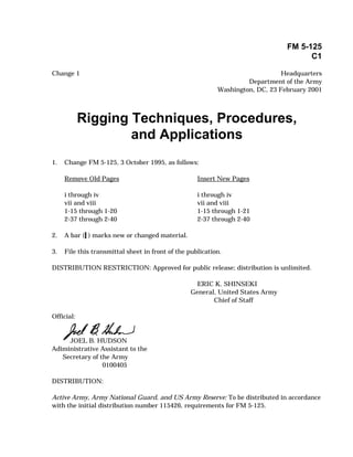
- 8. FM 5-125 Wire rope cutter Blade Seizings Figure 1-11. Wire-rope cutter the two central seizings. Push the blade other in addition to bending. Keep this down against the wire rope and strike the bending and moving of wires to a minimum top of the blade sharply with a sledge ham- to reduce wear. If the sheave or drum mer several times. Use the bolt clippers on diameter is sufficiently large, the loss of wire rope of fairly small diameter; however, strength due to bending wire rope around use an oxyacetylene torch on wire rope of it will be about 5 or 6 percent. In all cases, any diameter. The hacksaw and cold chisel keep the speed of the rope over the sheaves are slower methods of cutting. or drum as slow as is consistent with effi- cient work to decrease wear on the rope. It DRUMS AND SHEAVES is impossible to give an absolute minimum The size and location of the sheaves and size for each sheave or drum, since a num- drums about which wire rope operates and ber of factors enter into this decision. How- the speed with which the rope passes over ever, Table 1-4, page 1-16, shows the the sheaves have a definite effect on the minimum recommended sheave and drum rope's strength and service life. diameters for several wire-rope sizes. The sheave diameter always should be as large as possible and, except for very flexible Size rope, never less than 20 times the wire- Each time wire rope is bent, the individual rope dia meter. This figure has been strands must move with respect to each adopted widely. Rope 1-15
- 9. C1, FM 5-125 FM 5-125 Table 1-4. Minimum tread diameter of drums and sheaves Rope Minimum Tread Diameter for Given Rope Diameter Construction* (inches) (inches) 6x7 6 x 19 6 x 37 8 x 19 1/4 10 1/2 8 1/2 6 1/2 3/8 15 3/4 12 3/4 6 3/4 9 3/4 1/2 21 17 9 13 5/8 26 1/4 21 1/4 11 1/4 16 1/4 3/4 31 1/2 25 1/2 13 1/2 19 1/2 7/8 36 3/4 29 3/4 15 3/4 22 3/4 1 42 34 18 26 1 1/8 47 1/4 38 1/4 20 1/4 29 1/4 1 1/4 52 1/2 42 1/2 22 1/2 32 1/2 1 1/2 63 51 27 39 *Rope construction is strands and wires per strand. Location in smooth layers. Overlapping results in binding, causing snatches on the line when You should reeve the drums, sheaves, and blocks used with wire rope and place them the rope is unwound. To produce smooth lay- in a manner to avoid reverse bends when- ers, start the rope against one flange of the ever possible (see Figure 1-12). A reverse drum and keep tension on the line while bend occurs when rope bends in one direc- winding. Start the rope against the right or tion around one block, drum, or sheave and left flange as necessary to match the direc- bends in the opposite direction around the tion of winding, so that when it is rewound next. This causes the individual wires and on the drum, the rope will curve in t h e strands to do an unnecessary amount of same manner as when it left the reel (see shifting, which increases wear. Where you Figure 1-13). A convenient method for deter- must use a reverse bend, the block, sheave, mining the proper flange of the drum for or drum causing the reversal should be of starting the rope is known as the hand rule larger diameter t h a n o r d i n a r i l y u s e d . (see Figure 1-14, page 1-18). The extended Space the bend as far apart as possible so there will be more time allowed between index finger in this figure points at the on- the bending motions. winding rope. The turns of the rope are wound on the drum close together to prevent the possibility of crushing and abrasion of Winding the rope while it is winding and to prevent Do not overlap wire-rope turns when wind- binding or snatching when it is unwound. If ing them on the drum of a winch; wrap them ne ce ssa r y, use a wood stick to force the 1-16 Rope
- 10. C1, FM 5-125 FM 5-125 Block Drum Drum Block 1 2 INCORRECT Block Drum Drum Block 3 4 CORRECT Figure 1-12. Avoiding reverse bends in wire rope Reel Drum Reel Drum Figure 1-13. Spooling wire rope from reel to drum Rope 1-17
- 11. C1, FM 5-125 FM 5-125 For right-lay rope For left-lay rope (use right hand) (use left hand) For overwind on drum— For underwind on drum— For overwind on drum— For underwind on drum— • The palm is down, • The palm is up, facing • The palm is down, • The palm is up, facing facing the drum. the drum. facing the drum. the drum. • The index finger points • The index finger points • The index finger points • The index finger points at on-winding rope. at on-winding rope. at on-winding rope. at on-winding rope. • The index finger must • The index finger must • The index finger must • The index finger must be closest to the be closest to the be closest to the be closest to the left-side flange. right-side flange. right-side flange. left-side flange. • The wind of the rope • The wind of the rope • The wind of the rope • The wind of the rope must be from left to must be from right to must be from right to must be from left to right along the drum. left along the drum. left along the drum. right along the drum. If a smooth-face drum has been cut or scored by an old rope, the methods shown may not apply. Figure 1-14. Determining starting flange of wire rope turns closer together. Striking the wire with layer; however, cross each turn of the rope a hammer or other metal object damages in the second layer over two turns of the the individual wires in the rope. If possi- first layer (see Figure 1-15). Wind the third b l e , w i n d o n l y a si n g l e l a y e r o f w i r e layer in the grooves of the second layer; rope on the drum. Where it is necessary to however, each turn of the rope will cross wind additional layers, wind them so as over two turns of the second layer. to eliminate the binding. Wind the second layer of turns over the first layer by placing the wire in the grooves formed by the first 1-18 Rope
- 12. C1, FM 5-125 FM 5-125 Cross-over two turns Cross-over to of the second layer second groove Turn back and first Five turns on Starting third layer cross-over for second layer second layer Figure 1-15. Winding wire-rope layers on a drum Rope 1-19
- 13. C1, FM 5-125 FM 5-125 INSPECTION OF WIRE ROPE Inspect wire rope frequently. Replace • Replace the wire rope when 1.25 per- frayed, kinked, worn, or corroded rope. The cent of the total rope wires are broken frequency of inspection is determined by in one strand in one lay. the amount of use. A rope that is used 1 or 2 hours a week requires less frequent inspec- • Replace wire rope with 200 or more tion than one that is used 24 hours a day. wires (6 x 37 class) when the surface wires show flat wear spots equal in width to 80 percent of the diameter of PROCEDURES the wires. On wire rope with larger Carefully inspect the weak points in rope and fewer total wires (6 x 7, 7 x 7, 7 x and the points where the greatest stress 19), replace it when the flat wear spot occurs. Worn spots will show up as shiny width is 50 percent of the wire diame- flattened spots on the wires. ter. Inspect broken wires to determine whether • Replace the wire if it is kinked or if it is a single broken wire or several wires. there is evidence of a popped core or Rope is unsafe if— broken wire strands protruding from the core strand. See Figure 1-17. • Individual wires are broken next to one another, causing unequal load dis- • Replace the wire rope if there is evi- tribution at this point. dence of an electrical arc strike (or other thermal damage) or crushing • Replace the wire rope when 2.5 per- damage. cent of the total rope wires are broken in the length of one lay, which is the • Replace the wire rope if there is evi- length along the rope that a strand dence of "birdcage" damage due to makes one complete spiral around the shock unloading. See Figure 1-17. rope core. See Figure 1-16. One lay Figure 1-16. Lay length 1-20 Rope
- 14. C1, FM 5-125 FM 5-125 Popped core Birdcage Figure 1-17. Unserviceable wire rope CAUSES OF FAILURE • Overwinding or crosswinding it on drums. Wire rope failure is commonly caused by— • Operating it over drums and sheaves • Sizing, constructing, or grading it that are out of alignment. incorrectly. • Permitting it to jump sheaves. • Allowing it to drag over obstacles. • Subjecting it to moisture or acid • Lubricating it improperly. fumes. • Operating it over drums and sheaves • Permitting it to untwist. of inadequate size. • Kinking. Rope 1-21
- 15. C1,FM 5-125 FM 5-125 after applying the working load and at fre- quent intervals thereafter. Retightening is necessary to compensate for the decrease in rope diameter that occurs when the strands adjust to the lengthwise strain caused by the load. Position the clips so that they are immediately accessible for inspection and maintenance. CLAMPS A wire clamp can be used with or without a thimble to make an eye in wire rope (see Fig- ure 2-51). Ordinarily, use a clamp to make an eye without a thimble. It has about 90 percent of the strength of the rope. Tighten the two end collars with wrenches to force the clamp to a good snug fit. This crushes the pieces of rope firmly against each other. Figure 2-51. Wire-rope clamps WEDGE SOCKET Use a wedge-socket end fitting when it is tapered socket. The loop of wire rope must necessary to change the fitting at frequent be inserted in the wedge socket so that the intervals (see Figure 2-52, page 2-38). The standing part of the wire rope will form a efficiency is about two-thirds of the strength nearly direct line to the clevis pin of the fit- of the rope. It is made in two parts. The ting. A properly installed wedge-socket con- socket itself has a tapered opening for the nection will tighten when a strain is placed wire rope and a small wedge to go into this on the wire rope. BASKET-SOCKET END FITTING The basket-socket end fittings include closed POURED METHOD sockets, open sockets, and bridge sockets The poured basket socket is the most satis- (see Figure 2-53, page 2-38). This socket is factory method in use (see Figure 2-54, page ordinarily attached to the end of the rope 2-39). If the socketing is properly done, a with molten zinc and is a permanent end wire rope, when tested to destruction, will rifting. If this fitting is properly made up, it is as strong as the rope itself. In all cases, break before it will pull out from the socket. the wire rope should lead from the socket in line with the axis of the socket. WARNING Never use babbitt, lead, or dry method to attach a basket socket end fitting. Knots, Splices, Attachments, and Ladders 2-37
- 16. C1, FM 5-125 FM 5-125 Live end Add clamp and Live end short cable Dead splice. end Dead 6 to 9 times end diameter Entering wrong side Not long enough READY-TO-USE CAUTION RIGHT Never clamp the live end to the dead WRONG end. Add the clamp and the short cable splice to the dead end as shown above. Figure 2-52. Wedge socket Wedge Bridge Open Closed socket socket socket socket Figure 2-53. Basket-socket end fittings 2-38 Knots, Splices, Attachments, and Ladders
- 17. C1,FM 5-125 FM 5-125 Spread the wires in each strand. Unlay the strands equal to the length of the socket. 1 Pour in molten zinc. Pull the rope into the socket. Place putty or clay here. 2 3 Figure 2-54. Attaching basket sockets by pouring Knots, Splices, Attachments, and Ladders 2-39
- 18. C1, FM 5-125 FM 5-125 DRY METHOD method (see Figure 2-55). The strength of the connection must be assumed to be The dry method should be used only when reduced to about one-sixth of the strength facilities are not available for the poured of a poured zinc connection. STANCHIONS The standard pipe stanchion is made up of a modifying it, for a suspended walkway 1-inch diameter pipe (see Figure 2-56). Each that uses two wire ropes on each side. stanchion is 40 inches long. Two 3/4-inch However, for handlines, remove or leave wire-rope clips are fastened through holes in off the lower wire-rope clip. For more infor- the pipe with the centers of the clips 36 mation on types and uses of stanchions, inches apart. Use this stanchion, without see TM 5-270. 2-40 Knots, Splices, Attachments, and Ladders