SlideShare una empresa de Scribd logo
1 de 8
Descargar para leer sin conexión
Application Note

  Implementing a Brushless DC Motor Controller on an IGLOO FPGA


1.0 Introduction
The main objective of the design is to commutate a Three-Phase BLDC Motor which has Hall
sensor feedback. The control inputs are available through hardware (I/Os) or a 2-wire serial
interface.

2.0 General Implementation Overview
A BLDC Motor is a synchronous motor with no damping or starting windings. Three logic signals
are decoded to determine the next winding sequence. A three-phase motor requires three push-
pull stages. In each of the six possible states, two outputs are active at a given time (current
flows in only two windings of the stator). Each state translates to electrical sectors.

                             Control Options


                     Start/Stop                                               BLDC
     START/STOP                     Commutation                              MOTOR
                      Control
                                       Logic

       CW/CCW        Direction          Stat e
                                                       DRIVE
                     Control           Machine        CIRCUIT
          RPM+
                       Speed            PWM
         RPM -        Control


                                       Hall F/B

                           Figure 1. BLDC Motor Control on IGLOO® Device


3.0 Reference Design Implementation
Simple Control Technique would be to sense the change in the state of the position of the rotor
and apply the next step/state for commutation. In case sensors are provided, the position is
known by reading the Hall sensors to determine the next state. An 8-bit pulse width modulation
(PWM) controller is used for speed control by varying the average voltage across the windings.
The PWM frequencies can be made variable based on motor specifications.


Ishnatek Systems & Services Private limited
Website: www.ishnatek.com
Contact email: shiva@ishnatek.com
Implementing a Brushless DC Motor Controller on an IGLOO FPGA


                                                                                             HALL_A
      MSTP_OR_BL_MD_H
                                                                           bldc_module       HALL_B
     PWM_FREQ_SEL_H
                                                                                             HALL_C
                                                                           bdbl_driver
                                                                              BLDC
                                        hw_ctrl                           StateMachine        PHASEA_H

         RUN_H
                                                                                              PHASEA_L
                             Debounce
                               blk                HW/SW
                                                   MUX                                        PHASEB_H
         STOP_H
                                                                                              PHASEB_L
         CW_OR_CCW_H                                                       control glue
                                                                              logic           PHASEC_H
         PLUS_H
                                                                                              PHASEC_L
         MINUS_H

                                                                             pwm_out
         MST_OR_BD_BL_H
                                                                         bdbl
                                                                        Speed     pwm_gen
         HW_SW                                                         control     _bdbl
                                                           sw_ctrl
                                                                      dutycycle
           RxD

           TxD                                    Serial
                                                                             clkgen


          SYS_CLK
                            Clkdiv                            clk_10mhz
                          20M_to_10M
          RST


                       Figure 2. BLDC Motor Control – Logic Block Diagram

The motor is commutated based on the signals given by the Hall Sensors mounted at various
positions inside the motor. Hall outputs change every 60 electrical degrees. The state of the
control switches and the Hall sensor signals are scanned continuously. A new voltage vector /
control trajectory is applied to the BLDC motor based on the Hall sensor signal conditions. This
mechanism is known as commutation.

                                                                                            A
    Q0                 A      Q2
                                                  B        Q4
                                                                            C
    Q1                        Q3                           Q5

                                                                                  C                    B
                    Figure 3 Push-Pull Stages of a 3-Phase BLDC Drive


2                                                                     Ishnatek Systems & Services Private limited
                                                                                       Website: www.ishnatek.com
                                                                                Contact email: shiva@ishnatek.com
Implementing a Brushless DC Motor Controller on an IGLOO FPGA


3.1 Sensored Drive – Hall Effect Sensors
The Hall position sensors sense the actual rotor position. The Hall outputs are monitored by the
controller and appropriate commutation sequence is applied to assist in commutating the motor.
The speed of the motor is varied by making use of PWM outputs on the output voltages.
Typically there are three Hall effect sensors provided inside the motor. The three sensors
comprise six states: 001, 010, 011, 100, 101, and 110. Six steps are required to perform one
complete electrical cycle. The electrical-to-mechanical ratio is based on the pole pairs inside the
motor. Each state corresponds to the actual rotor position inside the motor. This determines the
required direction of voltage vector based on the direction in which the rotor needs to be moved.
A vector table is generated for the sensor state and the next commutation sequence.
                                   1 Electrical Cycle

              0°       60°       120°        180°       240°      300°          360°                        540°                         720°

     Hall A
                   A
    Hall B
                                        B
    Hall C


               Chigh       Ahigh      Ahigh
                                                               C
                                                  Bhigh        Bhigh       Chigh     Chigh     Ahigh      Ahigh    Bhigh       Bhigh   Chigh
               Blow        Blow       Clow        Clow         Alow        Alow      Blow      Blow       Clow     Clow        Alow    Alow
                                        Figure 4. Commutation Using Hall Sensors
                                                        VM_HIGH


               AHigh                  BHigh
                       G
                             D
                                              G
                                                    D           CHigh G     D


                             S   Q0                 S
                                                        Q2                  S   Q4                                 A

               ALow          D        BLow          D
                                                               CLow         D
                       G                      G                        G

                             S   Q1                 S   Q3                  S   Q5                    C                    B
                                                        VM_LOW


                                                                                             Hall A
                                      Commutation
                                                                                             Hall C
                                       Sequencer                                             Hall B

                           Figure 5. External MOSFET Bridge Circuit for Commutation


Ishnatek Systems & Services Private limited                                                                                                     3
Website: www.ishnatek.com
Contact email: shiva@ishnatek.com
Implementing a Brushless DC Motor Controller on an IGLOO FPGA


3.2 Speed Control
The speed of the motor is directly proportional to the applied voltage. By varying the average
voltage across the windings, the RPM can be altered. This is achieved by altering the duty cycle
of the base PWM signal. Maximum speed is achieved when PWM is OFF. In that case, the
MOSFETs are ON for 100% of the commutation period. When PWM is turned ON, the speed is
proportional to the duty cycle setting.
Digital Control of RPM
A fixed internal 8-bit register is incremented or decremented upon receiving the RPM+ or RPM-
commands from the switches onboard or through the software interface. This alters the duty
cycle and hence the speed of the motor.

3.3 Commutation
Typical 3-Phase Current Waveforms:

                     1      2        3      4       5        6       1        2

         A


         B


         C

                    A      A       B        B       C       C       A        A
                    B      C       C        A       A       B       B        C

                           Figure 6. Six-Step Commutation Waveform

Figure 6 shows the commutation sequence for a typical 3-Phase BLDC Motor. Each phase is
active for 120 electrical degrees. At any given time/step interval, notice that only two phases are
active. The third phase is inactive or floating. This mechanism has built-in dead time and
assures that the two MOSFETs in the same bridge are not active at the same time.
The commutation sequence as shown above will be AB-AC-BC-BA-CA-CB-AB-AC… and
repeats from there on. Notice that during AB sequence, the upper side of the A bridge is active
while the lower side of B bridge is active. So current flows from DC+ through the A high side to
the motor winding across A and B, passes through the low side of the B bridge and to DC-. The

4                                                          Ishnatek Systems & Services Private limited
                                                                            Website: www.ishnatek.com
                                                                     Contact email: shiva@ishnatek.com
Implementing a Brushless DC Motor Controller on an IGLOO FPGA


commutation timing is determined based on the position of the rotor. In the case of a sensored
drive, the Hall effect sensor digital outputs determine the position of the rotor, which can be
used to move to the next logical sequence.

3.4 BLDC Control State Machine

                      !Start                          Bring Motor to Known
                                                      State for Fixed Time –
 RST                                                  Alignment Phase
               IDLE            Start          INIT
                                                                                 !Stop
                                                        Sensored

                                                                 HALL_SENSOR


                                 STOP_MOTOR              Stop


                        Figure 7. BLDC Control State Machine


Ishnatek Systems & Services Private limited                                                       5
Website: www.ishnatek.com
Contact email: shiva@ishnatek.com
Implementing a Brushless DC Motor Controller on an IGLOO FPGA


4.0 Waveforms
PWM to High Side
In this case the PWM signal is applied only to the high side of the MOSFET pair, while the low
side is driven for 100% of the commutation period.
                       AB   AC        BC      BA      CA        CB        AB        AC
                        1     2         3         4     5          6           1       2

        A
       Ahigh


       Alow

         B
        Bhigh

        Blow


         C

       Chigh


       Clow
                                      Figure 8. PWM to High Side


    Phase       PhaseA_H PhaseA_L          PhaseB_H   PhaseB_L PhaseC_H            PhaseC_L
    Phase1        PWM             0           0             1            0                 0
    Phase2         0              0           0             1          PWM                 0
    Phase3         0              1           0             0          PWM                 0
    Phase4         0              1          PWM            0            0                 0
    Phase5         0              0          PWM            0            0                 1
    Phase6        PWM             0           0             0            0                 1
                       Table 1. Phase Sequence When PWM to High Side


6                                                        Ishnatek Systems & Services Private limited
                                                                          Website: www.ishnatek.com
                                                                   Contact email: shiva@ishnatek.com
Implementing a Brushless DC Motor Controller on an IGLOO FPGA


5.0 I/Os
The following table describes the Main I/Os in the design.

Signal Name                       Input/                     Description                  Fusion
                                  Output                                                   Pin
RxD                                 Input     RS232 Receive                                 C31
TxD                                Output     RS232 Transmit                                B34
CW_OR_CCW_H                        Input      Motor Direction Control                       A31
                                              1 – Clockwise
                                              0 – Counterclockwise
MSTP_OR_BL_MD_H                     Input     For BLDC motor,                               A21
                                              PWM Mode
                                              1 – High Side PWM
                                              0 – Low Side PWM
STOP_H                              Input     Motor Stop                                     A7
MST_OR_BD_BL_H                      Input     For Brushed/Brushless motor                    B2
                                              1 – Brushed motor, 0 – Brushless motor
RUN_H                              Input      Motor Start/Run                               C4
SYS_RESET                          Input      System Reset (Pulse through Switch SW6)       C1
PHASEA_H                           Output     PhaseA – High Side Signal                     C26
PHASEA_L                           Output     Phase A – Low Side Signal                     B30
PHASEB_H                           Output     PhaseB – High Side Signal                     A36
PHASEB_L                           Output     PhaseB – Low Side Signal                      C32
PHASEC_H                           Output     PhaseC – High Side Signal                     C2
PHASEC_L                           Output     PhaseB – Low Side Signal                      A16
HALL_A                             Input      Hall Sensor A from Motor                      C6
HALL_B                             Input      Hall Sensor B from Motor                      B10
HALL_C                             Input      Hall Sensor C from Motor                      B24
HW_SW                              Input      Hardware or Software Control                  A35
                                              ON – Hardware, OFF – Software
PLUS_H                              Input     Increment Speed                               A23
MINUS_H                             Input     Decrement Speed                               A26
PWM_FREQ_SEL_H                      Input     PWM Frequency Select                          C14
                                              0 – 39 KHz, 1 – 78 KHz
SD                                 Output     Shutdown for MOSFET Driver                     C5
SYS_CLK                             Input     Sys Clock                                      A5

6.0 Conclusion
This design example allows the user to run a Three-Phase BLDC motor using the low-power
IGLOO device. The design has been specifically developed with the drive circuit in mind. Please
refer to the Icicle Motor control documentation for detailed usage of the IP and the features
available through hardware and software.


Ishnatek Systems & Services Private limited                                                        7
Website: www.ishnatek.com
Contact email: shiva@ishnatek.com
Implementing a Brushless DC Motor Controller on an IGLOO FPGA


Appendix A – BLDC Motor Controller Design Example
Design Files Summary
Files                                             Functionality
baud_clk_gen.v           This block generates the desired baud clock for Serial Comm
clk_by_2.v               Divides input clock by 2 – Toggle F/F
clk_gen.v                Clock Generator Block
debounce.v               Debounce Logic
debounce_blk.v           Interconnects all debounce blocks.
div_by_16.v              Divide by 16 block for serial communication – baud clock
divideby5.v              Derived Clock for internal use
clkdiv_20M_to_10M.v      Generate 10 MHz from 20 MHz Input
global.v                 Defines/Parameters for the design
recv_control.v           This block receives data serially on RxD.
serial.v                 This block generates software controls for bldc motor
mux_hw_sw.v              This block multiplexes between hardware and software controls
xmit_control.v           This block transmits data serially on TxD.
bd_bl_speedcontrol.v     Speed control block for BLDC driver
pwm_gen_bdbl.v           BLDC clock – PWM generator
bdbl_driver.v            BLDC driver module
top_serial.v             This block connects xmit_control, recv_control, serial,
                         baud_clk_gen and div_by_16
top_bldc.v               This block connects bldc_driver, pwm_generator, and
                         bd_bl_speedcontrol block
bldc_ip.v                This block interconnects top_bldc and clk_gen
top_bldc_ip.v            This block interconnects mux_hw_sw,debounce_blk and bldc_ip
top_tb.v                 Testbench for bldc_ip


About Ishnatek
Ishnatek offers FPGA design and hardware prototyping services. Ishnatek offers Design and
Verification Services for embedded solutions. We have IPs such as 8031, RTC, Timers,
Enhanced PWM, UART/SIO/IrDA, I2C, LED Drivers and Key scan, Parallel Port, ECP/EPP, etc.,
which can be building blocks for your embedded controller solutions.

8                                                         Ishnatek Systems & Services Private limited
                                                                           Website: www.ishnatek.com
                                                                    Contact email: shiva@ishnatek.com

Más contenido relacionado

Último

The basics of sentences session 3pptx.pptx
The basics of sentences session 3pptx.pptxThe basics of sentences session 3pptx.pptx
The basics of sentences session 3pptx.pptxheathfieldcps1
 
Presentation by Andreas Schleicher Tackling the School Absenteeism Crisis 30 ...
Presentation by Andreas Schleicher Tackling the School Absenteeism Crisis 30 ...Presentation by Andreas Schleicher Tackling the School Absenteeism Crisis 30 ...
Presentation by Andreas Schleicher Tackling the School Absenteeism Crisis 30 ...EduSkills OECD
 
Holdier Curriculum Vitae (April 2024).pdf
Holdier Curriculum Vitae (April 2024).pdfHoldier Curriculum Vitae (April 2024).pdf
Holdier Curriculum Vitae (April 2024).pdfagholdier
 
microwave assisted reaction. General introduction
microwave assisted reaction. General introductionmicrowave assisted reaction. General introduction
microwave assisted reaction. General introductionMaksud Ahmed
 
Food Chain and Food Web (Ecosystem) EVS, B. Pharmacy 1st Year, Sem-II
Food Chain and Food Web (Ecosystem) EVS, B. Pharmacy 1st Year, Sem-IIFood Chain and Food Web (Ecosystem) EVS, B. Pharmacy 1st Year, Sem-II
Food Chain and Food Web (Ecosystem) EVS, B. Pharmacy 1st Year, Sem-IIShubhangi Sonawane
 
Role Of Transgenic Animal In Target Validation-1.pptx
Role Of Transgenic Animal In Target Validation-1.pptxRole Of Transgenic Animal In Target Validation-1.pptx
Role Of Transgenic Animal In Target Validation-1.pptxNikitaBankoti2
 
2024-NATIONAL-LEARNING-CAMP-AND-OTHER.pptx
2024-NATIONAL-LEARNING-CAMP-AND-OTHER.pptx2024-NATIONAL-LEARNING-CAMP-AND-OTHER.pptx
2024-NATIONAL-LEARNING-CAMP-AND-OTHER.pptxMaritesTamaniVerdade
 
Russian Escort Service in Delhi 11k Hotel Foreigner Russian Call Girls in Delhi
Russian Escort Service in Delhi 11k Hotel Foreigner Russian Call Girls in DelhiRussian Escort Service in Delhi 11k Hotel Foreigner Russian Call Girls in Delhi
Russian Escort Service in Delhi 11k Hotel Foreigner Russian Call Girls in Delhikauryashika82
 
Energy Resources. ( B. Pharmacy, 1st Year, Sem-II) Natural Resources
Energy Resources. ( B. Pharmacy, 1st Year, Sem-II) Natural ResourcesEnergy Resources. ( B. Pharmacy, 1st Year, Sem-II) Natural Resources
Energy Resources. ( B. Pharmacy, 1st Year, Sem-II) Natural ResourcesShubhangi Sonawane
 
Measures of Dispersion and Variability: Range, QD, AD and SD
Measures of Dispersion and Variability: Range, QD, AD and SDMeasures of Dispersion and Variability: Range, QD, AD and SD
Measures of Dispersion and Variability: Range, QD, AD and SDThiyagu K
 
Beyond the EU: DORA and NIS 2 Directive's Global Impact
Beyond the EU: DORA and NIS 2 Directive's Global ImpactBeyond the EU: DORA and NIS 2 Directive's Global Impact
Beyond the EU: DORA and NIS 2 Directive's Global ImpactPECB
 
Introduction to Nonprofit Accounting: The Basics
Introduction to Nonprofit Accounting: The BasicsIntroduction to Nonprofit Accounting: The Basics
Introduction to Nonprofit Accounting: The BasicsTechSoup
 
PROCESS RECORDING FORMAT.docx
PROCESS      RECORDING        FORMAT.docxPROCESS      RECORDING        FORMAT.docx
PROCESS RECORDING FORMAT.docxPoojaSen20
 
ICT Role in 21st Century Education & its Challenges.pptx
ICT Role in 21st Century Education & its Challenges.pptxICT Role in 21st Century Education & its Challenges.pptx
ICT Role in 21st Century Education & its Challenges.pptxAreebaZafar22
 
Ecological Succession. ( ECOSYSTEM, B. Pharmacy, 1st Year, Sem-II, Environmen...
Ecological Succession. ( ECOSYSTEM, B. Pharmacy, 1st Year, Sem-II, Environmen...Ecological Succession. ( ECOSYSTEM, B. Pharmacy, 1st Year, Sem-II, Environmen...
Ecological Succession. ( ECOSYSTEM, B. Pharmacy, 1st Year, Sem-II, Environmen...Shubhangi Sonawane
 
Python Notes for mca i year students osmania university.docx
Python Notes for mca i year students osmania university.docxPython Notes for mca i year students osmania university.docx
Python Notes for mca i year students osmania university.docxRamakrishna Reddy Bijjam
 
Making and Justifying Mathematical Decisions.pdf
Making and Justifying Mathematical Decisions.pdfMaking and Justifying Mathematical Decisions.pdf
Making and Justifying Mathematical Decisions.pdfChris Hunter
 
Basic Civil Engineering first year Notes- Chapter 4 Building.pptx
Basic Civil Engineering first year Notes- Chapter 4 Building.pptxBasic Civil Engineering first year Notes- Chapter 4 Building.pptx
Basic Civil Engineering first year Notes- Chapter 4 Building.pptxDenish Jangid
 
Unit-IV; Professional Sales Representative (PSR).pptx
Unit-IV; Professional Sales Representative (PSR).pptxUnit-IV; Professional Sales Representative (PSR).pptx
Unit-IV; Professional Sales Representative (PSR).pptxVishalSingh1417
 
Micro-Scholarship, What it is, How can it help me.pdf
Micro-Scholarship, What it is, How can it help me.pdfMicro-Scholarship, What it is, How can it help me.pdf
Micro-Scholarship, What it is, How can it help me.pdfPoh-Sun Goh
 

Último (20)

The basics of sentences session 3pptx.pptx
The basics of sentences session 3pptx.pptxThe basics of sentences session 3pptx.pptx
The basics of sentences session 3pptx.pptx
 
Presentation by Andreas Schleicher Tackling the School Absenteeism Crisis 30 ...
Presentation by Andreas Schleicher Tackling the School Absenteeism Crisis 30 ...Presentation by Andreas Schleicher Tackling the School Absenteeism Crisis 30 ...
Presentation by Andreas Schleicher Tackling the School Absenteeism Crisis 30 ...
 
Holdier Curriculum Vitae (April 2024).pdf
Holdier Curriculum Vitae (April 2024).pdfHoldier Curriculum Vitae (April 2024).pdf
Holdier Curriculum Vitae (April 2024).pdf
 
microwave assisted reaction. General introduction
microwave assisted reaction. General introductionmicrowave assisted reaction. General introduction
microwave assisted reaction. General introduction
 
Food Chain and Food Web (Ecosystem) EVS, B. Pharmacy 1st Year, Sem-II
Food Chain and Food Web (Ecosystem) EVS, B. Pharmacy 1st Year, Sem-IIFood Chain and Food Web (Ecosystem) EVS, B. Pharmacy 1st Year, Sem-II
Food Chain and Food Web (Ecosystem) EVS, B. Pharmacy 1st Year, Sem-II
 
Role Of Transgenic Animal In Target Validation-1.pptx
Role Of Transgenic Animal In Target Validation-1.pptxRole Of Transgenic Animal In Target Validation-1.pptx
Role Of Transgenic Animal In Target Validation-1.pptx
 
2024-NATIONAL-LEARNING-CAMP-AND-OTHER.pptx
2024-NATIONAL-LEARNING-CAMP-AND-OTHER.pptx2024-NATIONAL-LEARNING-CAMP-AND-OTHER.pptx
2024-NATIONAL-LEARNING-CAMP-AND-OTHER.pptx
 
Russian Escort Service in Delhi 11k Hotel Foreigner Russian Call Girls in Delhi
Russian Escort Service in Delhi 11k Hotel Foreigner Russian Call Girls in DelhiRussian Escort Service in Delhi 11k Hotel Foreigner Russian Call Girls in Delhi
Russian Escort Service in Delhi 11k Hotel Foreigner Russian Call Girls in Delhi
 
Energy Resources. ( B. Pharmacy, 1st Year, Sem-II) Natural Resources
Energy Resources. ( B. Pharmacy, 1st Year, Sem-II) Natural ResourcesEnergy Resources. ( B. Pharmacy, 1st Year, Sem-II) Natural Resources
Energy Resources. ( B. Pharmacy, 1st Year, Sem-II) Natural Resources
 
Measures of Dispersion and Variability: Range, QD, AD and SD
Measures of Dispersion and Variability: Range, QD, AD and SDMeasures of Dispersion and Variability: Range, QD, AD and SD
Measures of Dispersion and Variability: Range, QD, AD and SD
 
Beyond the EU: DORA and NIS 2 Directive's Global Impact
Beyond the EU: DORA and NIS 2 Directive's Global ImpactBeyond the EU: DORA and NIS 2 Directive's Global Impact
Beyond the EU: DORA and NIS 2 Directive's Global Impact
 
Introduction to Nonprofit Accounting: The Basics
Introduction to Nonprofit Accounting: The BasicsIntroduction to Nonprofit Accounting: The Basics
Introduction to Nonprofit Accounting: The Basics
 
PROCESS RECORDING FORMAT.docx
PROCESS      RECORDING        FORMAT.docxPROCESS      RECORDING        FORMAT.docx
PROCESS RECORDING FORMAT.docx
 
ICT Role in 21st Century Education & its Challenges.pptx
ICT Role in 21st Century Education & its Challenges.pptxICT Role in 21st Century Education & its Challenges.pptx
ICT Role in 21st Century Education & its Challenges.pptx
 
Ecological Succession. ( ECOSYSTEM, B. Pharmacy, 1st Year, Sem-II, Environmen...
Ecological Succession. ( ECOSYSTEM, B. Pharmacy, 1st Year, Sem-II, Environmen...Ecological Succession. ( ECOSYSTEM, B. Pharmacy, 1st Year, Sem-II, Environmen...
Ecological Succession. ( ECOSYSTEM, B. Pharmacy, 1st Year, Sem-II, Environmen...
 
Python Notes for mca i year students osmania university.docx
Python Notes for mca i year students osmania university.docxPython Notes for mca i year students osmania university.docx
Python Notes for mca i year students osmania university.docx
 
Making and Justifying Mathematical Decisions.pdf
Making and Justifying Mathematical Decisions.pdfMaking and Justifying Mathematical Decisions.pdf
Making and Justifying Mathematical Decisions.pdf
 
Basic Civil Engineering first year Notes- Chapter 4 Building.pptx
Basic Civil Engineering first year Notes- Chapter 4 Building.pptxBasic Civil Engineering first year Notes- Chapter 4 Building.pptx
Basic Civil Engineering first year Notes- Chapter 4 Building.pptx
 
Unit-IV; Professional Sales Representative (PSR).pptx
Unit-IV; Professional Sales Representative (PSR).pptxUnit-IV; Professional Sales Representative (PSR).pptx
Unit-IV; Professional Sales Representative (PSR).pptx
 
Micro-Scholarship, What it is, How can it help me.pdf
Micro-Scholarship, What it is, How can it help me.pdfMicro-Scholarship, What it is, How can it help me.pdf
Micro-Scholarship, What it is, How can it help me.pdf
 

Destacado

2024 State of Marketing Report – by Hubspot
2024 State of Marketing Report – by Hubspot2024 State of Marketing Report – by Hubspot
2024 State of Marketing Report – by HubspotMarius Sescu
 
Everything You Need To Know About ChatGPT
Everything You Need To Know About ChatGPTEverything You Need To Know About ChatGPT
Everything You Need To Know About ChatGPTExpeed Software
 
Product Design Trends in 2024 | Teenage Engineerings
Product Design Trends in 2024 | Teenage EngineeringsProduct Design Trends in 2024 | Teenage Engineerings
Product Design Trends in 2024 | Teenage EngineeringsPixeldarts
 
How Race, Age and Gender Shape Attitudes Towards Mental Health
How Race, Age and Gender Shape Attitudes Towards Mental HealthHow Race, Age and Gender Shape Attitudes Towards Mental Health
How Race, Age and Gender Shape Attitudes Towards Mental HealthThinkNow
 
AI Trends in Creative Operations 2024 by Artwork Flow.pdf
AI Trends in Creative Operations 2024 by Artwork Flow.pdfAI Trends in Creative Operations 2024 by Artwork Flow.pdf
AI Trends in Creative Operations 2024 by Artwork Flow.pdfmarketingartwork
 
PEPSICO Presentation to CAGNY Conference Feb 2024
PEPSICO Presentation to CAGNY Conference Feb 2024PEPSICO Presentation to CAGNY Conference Feb 2024
PEPSICO Presentation to CAGNY Conference Feb 2024Neil Kimberley
 
Content Methodology: A Best Practices Report (Webinar)
Content Methodology: A Best Practices Report (Webinar)Content Methodology: A Best Practices Report (Webinar)
Content Methodology: A Best Practices Report (Webinar)contently
 
How to Prepare For a Successful Job Search for 2024
How to Prepare For a Successful Job Search for 2024How to Prepare For a Successful Job Search for 2024
How to Prepare For a Successful Job Search for 2024Albert Qian
 
Social Media Marketing Trends 2024 // The Global Indie Insights
Social Media Marketing Trends 2024 // The Global Indie InsightsSocial Media Marketing Trends 2024 // The Global Indie Insights
Social Media Marketing Trends 2024 // The Global Indie InsightsKurio // The Social Media Age(ncy)
 
Trends In Paid Search: Navigating The Digital Landscape In 2024
Trends In Paid Search: Navigating The Digital Landscape In 2024Trends In Paid Search: Navigating The Digital Landscape In 2024
Trends In Paid Search: Navigating The Digital Landscape In 2024Search Engine Journal
 
5 Public speaking tips from TED - Visualized summary
5 Public speaking tips from TED - Visualized summary5 Public speaking tips from TED - Visualized summary
5 Public speaking tips from TED - Visualized summarySpeakerHub
 
ChatGPT and the Future of Work - Clark Boyd
ChatGPT and the Future of Work - Clark Boyd ChatGPT and the Future of Work - Clark Boyd
ChatGPT and the Future of Work - Clark Boyd Clark Boyd
 
Getting into the tech field. what next
Getting into the tech field. what next Getting into the tech field. what next
Getting into the tech field. what next Tessa Mero
 
Google's Just Not That Into You: Understanding Core Updates & Search Intent
Google's Just Not That Into You: Understanding Core Updates & Search IntentGoogle's Just Not That Into You: Understanding Core Updates & Search Intent
Google's Just Not That Into You: Understanding Core Updates & Search IntentLily Ray
 
Time Management & Productivity - Best Practices
Time Management & Productivity -  Best PracticesTime Management & Productivity -  Best Practices
Time Management & Productivity - Best PracticesVit Horky
 
The six step guide to practical project management
The six step guide to practical project managementThe six step guide to practical project management
The six step guide to practical project managementMindGenius
 
Beginners Guide to TikTok for Search - Rachel Pearson - We are Tilt __ Bright...
Beginners Guide to TikTok for Search - Rachel Pearson - We are Tilt __ Bright...Beginners Guide to TikTok for Search - Rachel Pearson - We are Tilt __ Bright...
Beginners Guide to TikTok for Search - Rachel Pearson - We are Tilt __ Bright...RachelPearson36
 

Destacado (20)

2024 State of Marketing Report – by Hubspot
2024 State of Marketing Report – by Hubspot2024 State of Marketing Report – by Hubspot
2024 State of Marketing Report – by Hubspot
 
Everything You Need To Know About ChatGPT
Everything You Need To Know About ChatGPTEverything You Need To Know About ChatGPT
Everything You Need To Know About ChatGPT
 
Product Design Trends in 2024 | Teenage Engineerings
Product Design Trends in 2024 | Teenage EngineeringsProduct Design Trends in 2024 | Teenage Engineerings
Product Design Trends in 2024 | Teenage Engineerings
 
How Race, Age and Gender Shape Attitudes Towards Mental Health
How Race, Age and Gender Shape Attitudes Towards Mental HealthHow Race, Age and Gender Shape Attitudes Towards Mental Health
How Race, Age and Gender Shape Attitudes Towards Mental Health
 
AI Trends in Creative Operations 2024 by Artwork Flow.pdf
AI Trends in Creative Operations 2024 by Artwork Flow.pdfAI Trends in Creative Operations 2024 by Artwork Flow.pdf
AI Trends in Creative Operations 2024 by Artwork Flow.pdf
 
Skeleton Culture Code
Skeleton Culture CodeSkeleton Culture Code
Skeleton Culture Code
 
PEPSICO Presentation to CAGNY Conference Feb 2024
PEPSICO Presentation to CAGNY Conference Feb 2024PEPSICO Presentation to CAGNY Conference Feb 2024
PEPSICO Presentation to CAGNY Conference Feb 2024
 
Content Methodology: A Best Practices Report (Webinar)
Content Methodology: A Best Practices Report (Webinar)Content Methodology: A Best Practices Report (Webinar)
Content Methodology: A Best Practices Report (Webinar)
 
How to Prepare For a Successful Job Search for 2024
How to Prepare For a Successful Job Search for 2024How to Prepare For a Successful Job Search for 2024
How to Prepare For a Successful Job Search for 2024
 
Social Media Marketing Trends 2024 // The Global Indie Insights
Social Media Marketing Trends 2024 // The Global Indie InsightsSocial Media Marketing Trends 2024 // The Global Indie Insights
Social Media Marketing Trends 2024 // The Global Indie Insights
 
Trends In Paid Search: Navigating The Digital Landscape In 2024
Trends In Paid Search: Navigating The Digital Landscape In 2024Trends In Paid Search: Navigating The Digital Landscape In 2024
Trends In Paid Search: Navigating The Digital Landscape In 2024
 
5 Public speaking tips from TED - Visualized summary
5 Public speaking tips from TED - Visualized summary5 Public speaking tips from TED - Visualized summary
5 Public speaking tips from TED - Visualized summary
 
ChatGPT and the Future of Work - Clark Boyd
ChatGPT and the Future of Work - Clark Boyd ChatGPT and the Future of Work - Clark Boyd
ChatGPT and the Future of Work - Clark Boyd
 
Getting into the tech field. what next
Getting into the tech field. what next Getting into the tech field. what next
Getting into the tech field. what next
 
Google's Just Not That Into You: Understanding Core Updates & Search Intent
Google's Just Not That Into You: Understanding Core Updates & Search IntentGoogle's Just Not That Into You: Understanding Core Updates & Search Intent
Google's Just Not That Into You: Understanding Core Updates & Search Intent
 
How to have difficult conversations
How to have difficult conversations How to have difficult conversations
How to have difficult conversations
 
Introduction to Data Science
Introduction to Data ScienceIntroduction to Data Science
Introduction to Data Science
 
Time Management & Productivity - Best Practices
Time Management & Productivity -  Best PracticesTime Management & Productivity -  Best Practices
Time Management & Productivity - Best Practices
 
The six step guide to practical project management
The six step guide to practical project managementThe six step guide to practical project management
The six step guide to practical project management
 
Beginners Guide to TikTok for Search - Rachel Pearson - We are Tilt __ Bright...
Beginners Guide to TikTok for Search - Rachel Pearson - We are Tilt __ Bright...Beginners Guide to TikTok for Search - Rachel Pearson - We are Tilt __ Bright...
Beginners Guide to TikTok for Search - Rachel Pearson - We are Tilt __ Bright...
 

23359381 bldc-motor-control-an

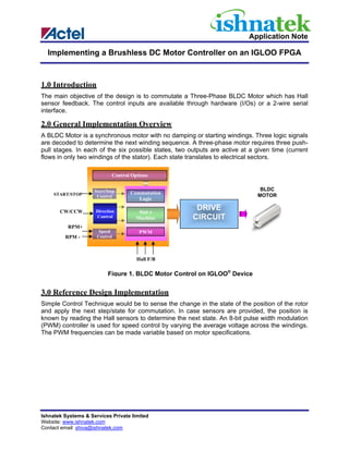
  • 1. Application Note Implementing a Brushless DC Motor Controller on an IGLOO FPGA 1.0 Introduction The main objective of the design is to commutate a Three-Phase BLDC Motor which has Hall sensor feedback. The control inputs are available through hardware (I/Os) or a 2-wire serial interface. 2.0 General Implementation Overview A BLDC Motor is a synchronous motor with no damping or starting windings. Three logic signals are decoded to determine the next winding sequence. A three-phase motor requires three push- pull stages. In each of the six possible states, two outputs are active at a given time (current flows in only two windings of the stator). Each state translates to electrical sectors. Control Options Start/Stop BLDC START/STOP Commutation MOTOR Control Logic CW/CCW Direction Stat e DRIVE Control Machine CIRCUIT RPM+ Speed PWM RPM - Control Hall F/B Figure 1. BLDC Motor Control on IGLOO® Device 3.0 Reference Design Implementation Simple Control Technique would be to sense the change in the state of the position of the rotor and apply the next step/state for commutation. In case sensors are provided, the position is known by reading the Hall sensors to determine the next state. An 8-bit pulse width modulation (PWM) controller is used for speed control by varying the average voltage across the windings. The PWM frequencies can be made variable based on motor specifications. Ishnatek Systems & Services Private limited Website: www.ishnatek.com Contact email: shiva@ishnatek.com
  • 2. Implementing a Brushless DC Motor Controller on an IGLOO FPGA HALL_A MSTP_OR_BL_MD_H bldc_module HALL_B PWM_FREQ_SEL_H HALL_C bdbl_driver BLDC hw_ctrl StateMachine PHASEA_H RUN_H PHASEA_L Debounce blk HW/SW MUX PHASEB_H STOP_H PHASEB_L CW_OR_CCW_H control glue logic PHASEC_H PLUS_H PHASEC_L MINUS_H pwm_out MST_OR_BD_BL_H bdbl Speed pwm_gen HW_SW control _bdbl sw_ctrl dutycycle RxD TxD Serial clkgen SYS_CLK Clkdiv clk_10mhz 20M_to_10M RST Figure 2. BLDC Motor Control – Logic Block Diagram The motor is commutated based on the signals given by the Hall Sensors mounted at various positions inside the motor. Hall outputs change every 60 electrical degrees. The state of the control switches and the Hall sensor signals are scanned continuously. A new voltage vector / control trajectory is applied to the BLDC motor based on the Hall sensor signal conditions. This mechanism is known as commutation. A Q0 A Q2 B Q4 C Q1 Q3 Q5 C B Figure 3 Push-Pull Stages of a 3-Phase BLDC Drive 2 Ishnatek Systems & Services Private limited Website: www.ishnatek.com Contact email: shiva@ishnatek.com
  • 3. Implementing a Brushless DC Motor Controller on an IGLOO FPGA 3.1 Sensored Drive – Hall Effect Sensors The Hall position sensors sense the actual rotor position. The Hall outputs are monitored by the controller and appropriate commutation sequence is applied to assist in commutating the motor. The speed of the motor is varied by making use of PWM outputs on the output voltages. Typically there are three Hall effect sensors provided inside the motor. The three sensors comprise six states: 001, 010, 011, 100, 101, and 110. Six steps are required to perform one complete electrical cycle. The electrical-to-mechanical ratio is based on the pole pairs inside the motor. Each state corresponds to the actual rotor position inside the motor. This determines the required direction of voltage vector based on the direction in which the rotor needs to be moved. A vector table is generated for the sensor state and the next commutation sequence. 1 Electrical Cycle 0° 60° 120° 180° 240° 300° 360° 540° 720° Hall A A Hall B B Hall C Chigh Ahigh Ahigh C Bhigh Bhigh Chigh Chigh Ahigh Ahigh Bhigh Bhigh Chigh Blow Blow Clow Clow Alow Alow Blow Blow Clow Clow Alow Alow Figure 4. Commutation Using Hall Sensors VM_HIGH AHigh BHigh G D G D CHigh G D S Q0 S Q2 S Q4 A ALow D BLow D CLow D G G G S Q1 S Q3 S Q5 C B VM_LOW Hall A Commutation Hall C Sequencer Hall B Figure 5. External MOSFET Bridge Circuit for Commutation Ishnatek Systems & Services Private limited 3 Website: www.ishnatek.com Contact email: shiva@ishnatek.com
  • 4. Implementing a Brushless DC Motor Controller on an IGLOO FPGA 3.2 Speed Control The speed of the motor is directly proportional to the applied voltage. By varying the average voltage across the windings, the RPM can be altered. This is achieved by altering the duty cycle of the base PWM signal. Maximum speed is achieved when PWM is OFF. In that case, the MOSFETs are ON for 100% of the commutation period. When PWM is turned ON, the speed is proportional to the duty cycle setting. Digital Control of RPM A fixed internal 8-bit register is incremented or decremented upon receiving the RPM+ or RPM- commands from the switches onboard or through the software interface. This alters the duty cycle and hence the speed of the motor. 3.3 Commutation Typical 3-Phase Current Waveforms: 1 2 3 4 5 6 1 2 A B C A A B B C C A A B C C A A B B C Figure 6. Six-Step Commutation Waveform Figure 6 shows the commutation sequence for a typical 3-Phase BLDC Motor. Each phase is active for 120 electrical degrees. At any given time/step interval, notice that only two phases are active. The third phase is inactive or floating. This mechanism has built-in dead time and assures that the two MOSFETs in the same bridge are not active at the same time. The commutation sequence as shown above will be AB-AC-BC-BA-CA-CB-AB-AC… and repeats from there on. Notice that during AB sequence, the upper side of the A bridge is active while the lower side of B bridge is active. So current flows from DC+ through the A high side to the motor winding across A and B, passes through the low side of the B bridge and to DC-. The 4 Ishnatek Systems & Services Private limited Website: www.ishnatek.com Contact email: shiva@ishnatek.com
  • 5. Implementing a Brushless DC Motor Controller on an IGLOO FPGA commutation timing is determined based on the position of the rotor. In the case of a sensored drive, the Hall effect sensor digital outputs determine the position of the rotor, which can be used to move to the next logical sequence. 3.4 BLDC Control State Machine !Start Bring Motor to Known State for Fixed Time – RST Alignment Phase IDLE Start INIT !Stop Sensored HALL_SENSOR STOP_MOTOR Stop Figure 7. BLDC Control State Machine Ishnatek Systems & Services Private limited 5 Website: www.ishnatek.com Contact email: shiva@ishnatek.com
  • 6. Implementing a Brushless DC Motor Controller on an IGLOO FPGA 4.0 Waveforms PWM to High Side In this case the PWM signal is applied only to the high side of the MOSFET pair, while the low side is driven for 100% of the commutation period. AB AC BC BA CA CB AB AC 1 2 3 4 5 6 1 2 A Ahigh Alow B Bhigh Blow C Chigh Clow Figure 8. PWM to High Side Phase PhaseA_H PhaseA_L PhaseB_H PhaseB_L PhaseC_H PhaseC_L Phase1 PWM 0 0 1 0 0 Phase2 0 0 0 1 PWM 0 Phase3 0 1 0 0 PWM 0 Phase4 0 1 PWM 0 0 0 Phase5 0 0 PWM 0 0 1 Phase6 PWM 0 0 0 0 1 Table 1. Phase Sequence When PWM to High Side 6 Ishnatek Systems & Services Private limited Website: www.ishnatek.com Contact email: shiva@ishnatek.com
  • 7. Implementing a Brushless DC Motor Controller on an IGLOO FPGA 5.0 I/Os The following table describes the Main I/Os in the design. Signal Name Input/ Description Fusion Output Pin RxD Input RS232 Receive C31 TxD Output RS232 Transmit B34 CW_OR_CCW_H Input Motor Direction Control A31 1 – Clockwise 0 – Counterclockwise MSTP_OR_BL_MD_H Input For BLDC motor, A21 PWM Mode 1 – High Side PWM 0 – Low Side PWM STOP_H Input Motor Stop A7 MST_OR_BD_BL_H Input For Brushed/Brushless motor B2 1 – Brushed motor, 0 – Brushless motor RUN_H Input Motor Start/Run C4 SYS_RESET Input System Reset (Pulse through Switch SW6) C1 PHASEA_H Output PhaseA – High Side Signal C26 PHASEA_L Output Phase A – Low Side Signal B30 PHASEB_H Output PhaseB – High Side Signal A36 PHASEB_L Output PhaseB – Low Side Signal C32 PHASEC_H Output PhaseC – High Side Signal C2 PHASEC_L Output PhaseB – Low Side Signal A16 HALL_A Input Hall Sensor A from Motor C6 HALL_B Input Hall Sensor B from Motor B10 HALL_C Input Hall Sensor C from Motor B24 HW_SW Input Hardware or Software Control A35 ON – Hardware, OFF – Software PLUS_H Input Increment Speed A23 MINUS_H Input Decrement Speed A26 PWM_FREQ_SEL_H Input PWM Frequency Select C14 0 – 39 KHz, 1 – 78 KHz SD Output Shutdown for MOSFET Driver C5 SYS_CLK Input Sys Clock A5 6.0 Conclusion This design example allows the user to run a Three-Phase BLDC motor using the low-power IGLOO device. The design has been specifically developed with the drive circuit in mind. Please refer to the Icicle Motor control documentation for detailed usage of the IP and the features available through hardware and software. Ishnatek Systems & Services Private limited 7 Website: www.ishnatek.com Contact email: shiva@ishnatek.com
  • 8. Implementing a Brushless DC Motor Controller on an IGLOO FPGA Appendix A – BLDC Motor Controller Design Example Design Files Summary Files Functionality baud_clk_gen.v This block generates the desired baud clock for Serial Comm clk_by_2.v Divides input clock by 2 – Toggle F/F clk_gen.v Clock Generator Block debounce.v Debounce Logic debounce_blk.v Interconnects all debounce blocks. div_by_16.v Divide by 16 block for serial communication – baud clock divideby5.v Derived Clock for internal use clkdiv_20M_to_10M.v Generate 10 MHz from 20 MHz Input global.v Defines/Parameters for the design recv_control.v This block receives data serially on RxD. serial.v This block generates software controls for bldc motor mux_hw_sw.v This block multiplexes between hardware and software controls xmit_control.v This block transmits data serially on TxD. bd_bl_speedcontrol.v Speed control block for BLDC driver pwm_gen_bdbl.v BLDC clock – PWM generator bdbl_driver.v BLDC driver module top_serial.v This block connects xmit_control, recv_control, serial, baud_clk_gen and div_by_16 top_bldc.v This block connects bldc_driver, pwm_generator, and bd_bl_speedcontrol block bldc_ip.v This block interconnects top_bldc and clk_gen top_bldc_ip.v This block interconnects mux_hw_sw,debounce_blk and bldc_ip top_tb.v Testbench for bldc_ip About Ishnatek Ishnatek offers FPGA design and hardware prototyping services. Ishnatek offers Design and Verification Services for embedded solutions. We have IPs such as 8031, RTC, Timers, Enhanced PWM, UART/SIO/IrDA, I2C, LED Drivers and Key scan, Parallel Port, ECP/EPP, etc., which can be building blocks for your embedded controller solutions. 8 Ishnatek Systems & Services Private limited Website: www.ishnatek.com Contact email: shiva@ishnatek.com