1. Centrifugal Pumps
Pumps are machines that are used to transfer liquid from a location of low elevation to a
higher elevation. There are various types of pumps and they are classified in two major categories:
(1) dynamic or kinetic and (2) positive displacement.
Dynamic or kinetic are types of pumps in which energy is continuously added to the fluid to
increase its velocity. Centrifugal, jet and turbine pumps falls under this category.
Positive displacement pumps, however, are types, in which energy is continuously added by
application of force to an enclosed volume of fluid and resulting to a direct increase in its pressure.
Reciprocating, rotary and diaphragm pumps falls under this category.
CENTRIFUGAL PUMPS
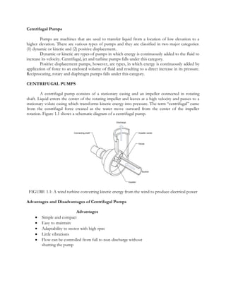
A centrifugal pump consists of a stationary casing and an impeller connected in rotating
shaft. Liquid enters the center of the rotating impeller and leaves at a high velocity and passes to a
stationary volute casing which transforms kinetic energy into pressure. The term “centrifugal” came
from the centrifugal force created as the water move outward from the center of the impeller
rotation. Figure 1.1 shows a schematic diagram of a centrifugal pump.
Discharge
Connecting shaft Impeller center
Volute
Suction
Impeller
FIGURE 1.1: A wind turbine converting kinetic energy from the wind to produce electrical power
Advantages and Disadvantages of Centrifugal Pumps
Advantages
Simple and compact
Easy to maintain
Adaptability to motor with high rpm
Little vibrations
Flow can be controlled from full to non-discharge without
shutting the pump
2. Disadvantages
Poor suction power
Usually needs priming
Cavitation may develop during operation
Needs multistage to increase discharge pressure
Cannot handle very viscous fluid
Check valve is required to avoid back flow
PUMP INSTALLATION
The following are some of the guidelines and precautions in installing a pump. It is also
important to consult the pump manufacturer for additional recommendations and further
information regarding the pump to be used. Note that the task of the designer is to keep the head
losses at a low value as possible. Figure shows a typical pump installation of a pump.
Make sure that the suction line is air tight. Any air leaking in the suction line forms air
pockets that reduce the pump capacity. Plan to install the suction line of the pump in a
manner that air pockets cannot form inside it.
Both the suction and discharge lines should be supported independently to protect the
casing from strains that may cause distortion to the pump.
All piping lines should be short and straight as possible, with minimum elbows, valves
and fittings.
The suction line should be at least one or two sizes larger than the suction flange. Use
eccentric reducer between the suction pipe and suction flange to have a better fluid flow.
The inlet end of the suction line should be at least 3 to 6 feet below the minimum water
level of the water source. Keep the suction inlet end away from agitation, because there
is a tendency for the air to mix with the liquid and may impair the operation of the
pump.
Maintain a length of straight piping of at least four to six pipe diameters long between
the elbow and suction flange of the pump to even out the flow of the water before it
enters the pump. An elbow attached at the suction side should have a large radius.
Install a gate valve and a check valve at the discharge line near the pump. The gate valve
is used to regulate the flow and the check valve prevents backflow of liquid into the
pump. Install a foot valve at the end of the suction line to hold the water in the suction
line of the pump. If foot valve is not used, end of the suction end should be belled out
to reduce the entrance velocity of the liquid.
Install the pump in a secure location and at the same time, available for inspection and
maintenance. If possible, place the pump as near the water source to keep suction lift at
a minimum.
The foundation should be heavy and rigid to reduce vibrations that may cause
misalignment between the pump shaft and motor or prime mover.
3. PUMP IN SERIES AND PARALLEL
Pumps can be installed in series or in parallel operation to achieve addition total dynamic
head or capacity.
Pumps in Series
Pumps in series are done by staging two pumps as shown in Figure 1.2. The total dynamic
head is increased at a given capacity as shown in the performance curve.
TWO PUMPS IN SERIES
CENTRIFUGAL
PUMP
160
TOTAL DYNAMIC HEAD IN FEET
140
Curve for 2 pumps in
120 series
100
Curve for 1 pump
80
60
40
20
0
40 80 120 160 200 240
GALLONS PER MINUTE
FIGURE 1.2: Pumps installed in series
Pumps in Parallel
Pumps in parallel are the result of installing two pumps as shown in Figure 1.3. The capacity
is doubled while maintaining the total dynamic head.
TWO PUMPS IN PARALLEL
CENTRIFUGAL
PUMP
160
TOTAL DYNAMIC HEAD IN FEET
140
120
Curve for 2 pumps in
100 Parallel
80
Curve for 1 pump
60
40
20
0
40 80 120 160 200 240
GALLONS PER MINUTE
FIGURE 1.3: Pumps installed in parallel