Cpm pert asgm. prashant
•Descargar como DOCX, PDF•
1 recomendación•1,519 vistas

project

Recomendados
Más contenido relacionado
La actualidad más candente
La actualidad más candente (19)
Similar a Cpm pert asgm. prashant
Similar a Cpm pert asgm. prashant (20)
Último
Último (20)
Cpm pert asgm. prashant
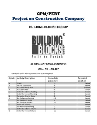
- 1. CPM/PERT Project on Construction Company BUILDING BLOCKS GROUP BY-PRASHANT SINGH BHADAURIA ROLL. NO – 2t3-107 Activity list for the Housing Construction by Building Block Activity Activity Description A B C D E F G H I J K L M N START Lay the Foundation Put up the Rough Wall Put up the Roof Install the Exterior Plumbing Install the Interior Plumbing Put up the Exterior Siding Do the Exterior Painting Do the Electric Work Put up the Wallboard Install the Flooring Do the Interior Painting Install the Exterior Fixtures Install the Interior Fixtures Immediate procedure -A B C C E D E,G C F,I J J H K,L Estimated Duration 2week 4 week 10 week 6 week 4 week 5 week 7 week 9 week 7 week 8 week 4 week 5 week 2 week 6 week
- 2. Given all the information in Table, Building Blocks now wants to develop answers to the following questions. 1. How can the project be displayed graphically to better visualize the flow of the activities? 2. What is the total time required to complete the project if no delays occur? 3. When do the individual activities need to start and finish (at the latest) to meet this project completion time? 4. When can the individual activities start and finish (at the earliest) if no delays occur? 5. Which are the critical bottleneck activities where any delays must be avoided to prevent delaying project completion? 6. For the other activities, how much delay can be tolerated without delaying project completion? 7. Given the uncertainties in accurately estimating activity durations, what is the probability of completing the project by the deadline? 8. If extra money is spent to expedite the project, what is the least expensive way of attempting to meet the target completion time (40 weeks)? 9. How should ongoing costs be monitored to try to keep the project within budget? Being a regular user of PERT/CPM, Building Blocks knows that this technique will provide invaluable help in answering these questions. USING A NETWORK TO VISUALLY DISPLAY A PROJECT
- 3. Network can be to represent and help analyze many kinds of problems. In much the same way, networks play a key role in dealing with projects. They enable showing the relationships between the activities and succinctly displaying the overall plan for the project. Project Networks A network used to represent a project is called a project network. A project network consists of a number of nodes (typically shown as small circles or rectangles) and a number of arcs (shown as arrows) that connect two different nodes. As Table indicates, three types of information are needed to describe a project. 1. Activity information: Break down the project into its individual activities (at the desired level of detail). 2. Precedence relationships: Identify the immediate predecessor(s) for each activity. 3. Time information: Estimate the duration of each activity. Scheduling the project with Pert/CPM: Activity Code A. Excavate B. Foundation C. Rough wall D. Roof E. Exterior plumbing F. Interior plumbing G. Exterior siding H. Exterior painting I. Electrical work J. Wallboard K. Flooring L. Interior painting M. Exterior fixtures N. Interior fixtures
- 4. SCHEDULING A PROJECT WITH PERT/CPM At the end of section, we mentioned that, the Building Blocks project manager, wants to use PERT/CPM to develop answers to a series of
- 5. questions. His first question has been answered in the preceding section. Here are the five questions that will be answered in this section. Question 2: What is the total time required to complete the project if no delays occur? Question 3: When do the individual activities need to start and finish (at the latest) to meet this project completion time? Question 4: When can the individual activities start and finish (at the earliest) if no delays occur? Question 5: Which are the critical bottleneck activities where any delays must be avoided to prevent delaying project completion? Question 6: For the other activities, how much delay can be tolerated without delaying project completion? The Critical Path How long should the project take? We noted earlier that summing the durations of all the activities gives a grand total of 79 weeks. However, this isn’t the answer to the question because some of the activities can be performed (roughly) simultaneously. What is relevant instead is the length of each path through the network. A path through a project network is one of the routes following the arcs from the START node to the FINISH node. The length of a path is the sum of the (estimated) durations of the activities on the path. . The six paths through the project network in Fig.1 are given in Table 2, along with the calculations of the lengths of these paths. The path lengths range from 31 weeks up to 44 weeks for the longest path (the fourth one in the table). So given these path lengths, what should be the (estimated) project duration (the total time required for the project)? Let us reason it out. Since the activities on any given path must be done in sequence with no overlap, the project duration cannot be shorter than the path length. However, the project duration can be longer because some activity on the path with multiple immediate predecessors mighthave to wait longer for an immediate predecessor not on the path to finish than for the oneon
- 6. the path. For example, consider the second path in Table 2 and focus on activity H. This activity has two immediate predecessors, one (activity G) not on the path and one (activity E) that is. After activity C finishes, only 4 more weeks are required for activity Ebut 13 weeks will be needed for activity D and then activity G to finish. Therefore, the project duration must be considerably longer than the length of the second path in the table. However, the project duration will not be longer than one particular path. This is the longest path through the project network. The activities on this path can be performed sequentially without interruption. (Otherwise, this would not be the longest path.) Therefore, the time required to reach the FINISH node equals the length of this path. Furthermore, all the shorter paths will reach the FINISH node no later than this. Here is the key conclusion. The (estimated) project duration equals the length of the longest path through the project network. This longest path is called the critical path. (If more than one path ties for the longest, they all are critical paths.) Thus, for the Reliable Construction Co. project, we have Critical path: START ->A->B->C->E->F->J->L->NFINISH (Estimated) project duration ->44 weeks. We now have answered Building Blocks Questions 2 and 5 given at the beginning of the section. If no delays occur, the total time required to complete the project should be about 44 weeks. Furthermore, the activities on this critical path are the critical bottleneck
- 7. The paths and path lengths through this project network Activities where any delays in their completion must be avoided to prevent delaying project completion. This is valuable information for Building Blocks, since he now knows that he should focus most of his attention on keeping these particular activities on schedule in striving to keep the overall project on schedule. Furthermore, if he decides to reduce the duration of the project (remember that bonus for completion within 40 weeks), these are the main activities where changes should be made to reduce their durations. For small project networks like Fig.1, finding all the paths and determining the longest path is a convenient way to identify the critical path. However, this is not an efficient procedure for larger projects. PERT/CPM uses a considerably more efficient procedure instead. Not only is this PERT/CPM procedure very efficient for larger projects, it also provides much more information than is available from finding all the paths. In particular, it answers all five of BUILDING BLOCKS questions listed at the beginning of the section rather than just two. These answers provide the key information needed to schedule all the activities and then to evaluate the consequences should any activities slip behind schedule. The components of this procedure are described in the remainder of this section. Scheduling Individual Activities
- 8. The PERT/CPM scheduling procedure begins by addressing Question 4: When can the individual activities start and finish (at the earliest) if no delays occur? Having no delays means that (1) the actual duration of each activity turns out to be the same as its estimatedduration and (2) each activity begins as soon as all its immediate predecessors are finished. The starting and finishing times of each activity if no delays occur anywhere in the project are called the earliest start time and the earliest finish time of the activity. These times are represented by the symbols ES =earliest start time for a particular activity, EF = earliest finish time for a particular activity, Where EF =ES + (estimated) duration of the activity. Rather than assigning calendar dates to these times, it is conventional instead to count the number of time periods (weeks for Homes project) from when the project started. Thus, Starting time for project =0. Since activity Astarts homes project, we have Activity A: ES =0, EF =0 +duration (2 weeks) =2, where the duration (in weeks) of activity A is given in Fig.1 as the boldfaced number next to this activity. Activity B can start as soon as activity A finishes, so Activity B: ES =EF for activity A =2, EF =2 +duration (4 weeks) =6.
- 9. This calculation of ES for activity B illustrates our first rule for obtaining ES. If an activity has only a single immediate predecessor, then ES for the activity =EF for the immediate predecessor. This rule (plus the calculation of each EF) immediately gives ES and EF for activity C, then for activities D, E, I, and then for activities G, F as well. Figure 2 shows ES andEF for each of these activities to the right of its node. For example, Activity G: ES =EF for activity D =22, EF =22 +duration (7 weeks) =29, which means that this activity (putting up the exterior siding) should start 22 weeks and finish 29 weeks after the start of the project. Now consider activity H, which has two immediate predecessors, activities G and E. Activity H must wait to start until both activities G and E are finished, which gives the following calculation. Immediate predecessors of activity H: Activity G has EF =29. Activity E has EF =20. Larger EF =29. Therefore, ES for activity H =larger EF above =29.
- 10. FIGURE -2 Earliest start time (ES) and earliest finish time (EF) values for the initial activities in Fig.1 that have only a single immediate predecessor.
- 11. This calculation illustrates the general rule for obtaining the earliest start time for any activity. Earliest Start Time Rule The earliest start time of an activity is equal to the largest of the earliest finish times of its immediate predecessors. In symbols, ES=largest EF of the immediate predecessors. When the activity has only a single immediate predecessor, this rule becomes the same as the first rule given earlier. However, it also allows any larger number of immediate predecessors as well. Applying this rule to the rest of the activities in Fig.2 (and calculating each EF from ES) yields the complete set of ES and EF values given in Fig. 3. Note that Fig. 22.3 also includes ES and EF values for the START and FINISH nodes. The reason is that these nodes are conventionally treated as dummy activitiesthat require no time. For the START node, ES=0=EF automatically. For the FINISH FIGURE-3 Earliest start time (ES) and earliest finish time (EF) values for all the activities (plus the START and FINISH nodes) of the Reliable Construction Co. project.
- 13. Node, the earliest start time rule is used to calculate ES in the usual way, as illustrated below. Immediate predecessors of the FINISH node: Activity M has EF=40. Activity N has EF= 44. Larger EF=44. Therefore, ES for the FINISH node=larger EF above =44. EF for the FINISH node =44+0=44. This last calculation indicates that the project should be completed in 44 weeks if everything stays on schedule according to the start and finish times for each activity given in Fig.3. (This answers Question 2.) Building Blocks now can use this schedule to inform the crew responsible for each activity as to when it should plan to start and finish its work. This process of starting with the initial activities and working forward in time toward the final activities to calculate all the ES and EF values is referred to as making a forward pass through the network. Keep in mind that the schedule obtained from this procedure assumes that the actual duration of each activity will turn out to be the same as its estimated duration. What happensif some activity takes longer than expected? Would this delay project completion? Perhaps, but not necessarily. It depends on which activity and the length of the delay. The next part of the procedure focuses on determining how much later than indicated in Fig.3 can an activity start or finish without delaying project completion. The latest start time for an activity is the latest possible time that it can start without delaying the completion of the project (so the FINISH node still is reached at its earliest finish time), assuming no subsequent delays in the project.
- 14. The latest finish time has the corresponding definition with respect to finishing the activity. In symbols, LS=latest start time for a particular activity, LF=latest finish time for a particular activity, Where LS=LF_(estimated) duration of the activity. To find LF, we have the following rule. Latest Finish Time Rule The latest finish time of an activity is equal to the smallest of the latest start times of its immediate successors. In symbols, LF =smallest LS of the immediate successors. Since an activity’s immediate successors cannot start until the activity finishes, this rule is saying that the activity must finish in time to enable all its immediate successors to begin by their latest start times. For example, consider activity M in Fig.1. Its only immediate successor is the FINISH node. This node must be reached by time 44 in order to complete the project within 44 weeks, so we begin by assigning values to this node as follows. FINISH node: LF=its EF =44, LS=44_0 =44. Now we can apply the latest finish time rule to activity M.
- 15. Activity M: LF =LS for the FINISH node =44, LS =44 _ duration (2 weeks) =42. (Since activity M is one of the activities that together complete the project, we also could have automatically set its LF equal to the earliest finish time of the FINISH node without applying the latest finish time rule.) Since activity M is the only immediate successor of activity H, we now can apply the latest finish time rule to the latter activity. Activity H: LF=LS for activity M =42, LS=42 _ duration (9 weeks) =33. Note that the procedure being illustrated above is to start with the final activities and work backward in time toward the initial activities to calculate all the LF and LS values. Thus, in contrast to the forward pass used to find earliest start and finish times, we now are making a backward pass through the network. Figure 22.4 shows the results of making a backward pass to its completion. For example, consider activity C, which has three immediate successors. Immediate successors of activity C: Activity D has LS =20. Activity E has LS =16. Activity I has LS =18. Smallest LS=16. Therefore, LF for activity C=smallest LS above =16. Building Blocks now knows that the schedule given in Fig.4 represents his “last chanceschedule.” Even if an activity starts and finishes as late as indicated in the figure, he stillwill be able to avoid delaying project
- 16. completion beyond 44 weeks as long as there is no subsequent slippage in the schedule. However, to allow for unexpected delays, he would prefer to stick instead to the earliest time schedule given in Fig.3 whenever possible in order to provide some slack in parts of the schedule. If the start and finish times in Fig.4 for a particular activity are later than the corresponding earliest times in Fig.3, then this activity has some slack in the schedule. The last part of the PERT/CPM procedure for scheduling a project is to identify this slack, and then to use this information to find the critical path. (This will answer both Questions 5 and 6.) FIGURE 22.4 Latest start time (LS) and latest finish time (LF) for all the activities (plus the START and FINISH nodes) of the Reliable Construction Co. project.
- 17. Identifying Slack in the Schedule To identify slack, it is convenient to combine the latest times in Fig .4 and the earliest times in Fig.3 into a single figure. Using activity M as an example, this is done by displaying the information for each activity as follows. (Note that the S or F in front of each parentheses will remind you of whether these are Start times or Finish times.) Figure 5 displays this information for the entire project. FIGURE 22.5 The complete project network showing ES and LS (in parentheses above the node) and EF and LF (in parentheses below the node) for each activity of the Housing project. The darker arrows show the critical path through the project network.
- 18. This figure makes it easy to see how much slack each activity has. The slack for an activity is the difference between its latest finish time and its earliest finish time. In symbols, Slack=LF_EF. (Since LF_EF=LS_ES, either difference actually can be used to calculate slack.)
- 19. For example, Slack for activity M =44_40=4. This indicates that activity M can be delayed up to 4 weeks beyond the earliest time schedule without delaying the completion of the project at 44 weeks. This makes sense, since the project is finished as soon as both activities M and N are completed and the earliest finish time for activity N (44) is 4 weeks later than for activity M (40). As long as activity N stays on schedule, the project still will finish at 44 weeks if any delays in starting activity M (perhaps due to preceding activities taking longer than expected) and in performing activity M do not cumulate more than 4 weeks. Table 3 shows the slack for each of the activities. Note that some of the activities have zero slack, indicating that any delays in these activities will delay project completion. This is how PERT/CPM identifies the critical path(s). Activity A B C D E F G H I J K L M N SLACK (LF_EF) 0 0 0 4 0 0 4 4 2 0 1 0 4 0 ON CRITICAL PATH? YES YES YES NO YES YES NO NO NO YES NO YES NO YES
- 20. Each activity with zero slack is on a critical path through the project network such that any delay along this path will delay project completion. Thus, the critical path is START _A_B_C_E_F_J_L_N_ FINISH, just as we found by a different method at the beginning of the section. This path is highlighted in Fig.5 by the darker arrows. It is the activities on this path that Building Blocksmust monitor with special care to keep the project on schedule. Review Now let us review Building Blocks questions at the beginning of the section and see how all of them have been answered by the PERT/CPM scheduling procedure. Question 2: What is the total time required to complete the project if no delays occur? This is the earliest finish time at the FINISH node (EF _ 44 weeks), as given at the bottom of Figs.3 and 5. Question 3: When do the individual activities need to start and finish (at the latest) to meet this project completion time? These times are the latest start times (LS) and latest finish times (LF) given in Figs..4 and .5. These times provide a “last chance schedule” to complete the project in 44 weeks if no further delays occur. Question 4: When can the individual activities start and finish (at the earliest) if no delays occur? These times are the earliest start times (ES) and earliest finish times (EF) given in Figs.3 and 5. These times usually are used to establish the initial schedule for the project. (Subsequent delays may force later adjustments in the schedule.) Question 5: Which are the critical bottleneck activities where any delays must be avoided to prevent delaying project completion? These are the activities on the critical path shown by the darker arrows in Fig. 5. Building Blocks needs to focus most ofhis attention on keeping these
- 21. particular activities on schedule in striving to keepthe overall project on schedule. Question 6: For the other activities, how much delay can be tolerated without delaying project completion? These tolerable delays are the positive slacks given in the middle column of Table 3. DEALING WITH UNCERTAIN ACTIVITY DURATIONS Now we come to the next of Building Blocks questions posed at the end of Sec.1. It is somewhat reassuring that the PERT/CPM scheduling procedure in the preceding section obtained an estimate of 44 weeks for the project duration. However, Building Blocks understands very well that this estimate is based on the assumption that the actual duration of each activity will turn out to be the same as its estimated duration for at least the activities on the critical path. Since the company does not have much prior experience with this kind of project, there is considerable uncertainty about how much time actually will be needed for each activity. In reality, the duration of each activity is a random variablehaving some probability distribution. The original version of PERT took this uncertainty into account by using three different types of estimates of the duration of an activity to obtain basic information about its probability distribution, as described below. The PERT Three-Estimate Approach The three estimates to be obtained for each activity are Most likely estimate (m) =estimate of the most likely value of the duration, Optimistic estimate (o) =estimate of the duration under the most favorable conditions, Pessimistic estimate (p) =estimate of the duration under the most unfavorable conditions. The intended location of these three estimates with respect to the probability distributionis shown in Fig.6.
- 22. Thus, the optimistic and pessimistic estimates are meant to lie at the extremes of what is possible, whereas the most likely estimate provides the highest point of the probability FIGURE 22.6 Model of the probability distribution of the duration of an activity for the PERT three-estimate approach: m =most likely estimate, o =optimistic estimate, and p=pessimistic estimate. Activity Optimistic estimate (o) Most likely estimate (m) Pessimistic estimate (p) Mean Variance A 1 2 3 2 1/9 B 2 3½ 8 4 1 C 6 9 18 10 4 D 4 5½ 10 6 1 E 1 4½ 5 4 4/9 F 4 4 10 5 1 G 5 6½ 11 7 1 H 5 8 17 9 4 I 3 7½ 9 7 1 J 3 9 9 8 1 K 4 4 4 4 0 L 1 5½ 7 5 1 M 1 2 3 2 1/9 N 5 5½ 9 6 4/9
- 23. distribution. PERT also assumes that the form of the probability distribution is a beta distribution (which has a shape like that in the figure) in order to calculate the mean (µ)and variance (¬2) of the probability distribution. For most probability distributions suchas the beta distribution, essentially the entire distribution lies inside the interval between(µ-3¬) and (µ+3¬). (For example, for a normal distribution, 99.73 percent of the distributionlies inside this interval.) Thus, the spread between the smallest and largest elapsedtimes in Fig.8 is roughly 6¬. Therefore, an approximate formula for ¬2 is . Similarly, an approximate formula for µis Intuitively, this formula is placing most of the weight on the most likely estimate and then small equal weights on the other two estimates.1 Building Blocks now has contacted the supervisor of each crew that will be responsible for one of the activities to request that these three estimates be made of the duration of the activity. The responses are shown in the first four columns of Table 4. The last two columns show the approximate mean and variance of the duration of each activity, as calculated from the formulas on p. 22–16. In this example, all the means happen to be the same as the estimated duration obtained in Table.1 of Sec.1. Therefore, if all the activity durations were to equal their means, the duration of the project stillwould be 44 weeks, so 3 weeks before the deadline. (See Fig.5 for the critical path requiring 44 weeks.)
- 24. However, this piece of information is not very reassuring to Building Blocks. He knows that the durations fluctuate around their means. Consequently, it is inevitable that the duration of some activities will be larger than the mean, perhaps even nearly as large as the pessimistic estimate, which could greatly delay the project. To check the worst case scenario, Building Blocks reexamines the project network with the duration of each activity set equal to the pessimistic estimate (as given in the fourth column of Table.4). Table.5 shows the six paths through this network (as given previously in Table 2) and the length of each path using the pessimistic estimates. The fourth path, which was the critical path in Fig.3, now has increased its length from 44 weeks to 69 weeks. However, the length of the first path, which originally was 40 weeks (as given in Table 2), now has increased all the way up to 70 weeks. Since this is the longest path, it is the critical path with pessimistic estimates, which would give a projectduration of 70 weeks. Given this dire (albeit unlikely) worst case scenario, Building Blocks realizes that it is far from certain that the deadline of 47 weeks will be met. But what is the probability of doing so? PERT/CPM makes three simplifying approximations to help calculate this probability. Three Simplifying Approximations To calculate the probability that project duration will be no more than 47 weeks, it is necessary to obtain the following information about the probability distribution of project duration. Probability Distribution of Project Duration. 1. What is the mean (denoted by µp) of this distribution? 2. What is the variance (denoted by ¬p2) of this distribution? 3. What is the form of this distribution? Recall that project duration equals the length (total elapsed time) of the longest path through the project network. However, just about any of the six paths listed in Table 5can turn out to be the longest path (and so the
- 25. critical path), depending upon what the durationof each activity turns out to be between its optimistic and pessimistic estimates. TABLE 5-The paths and path lengths through Housing project network when the duration of each activity equals its pessimistic estimate Since dealing with all these paths would be complicated, PERT/CPM focuses on just the following path. The mean critical path is the path through the project network that would be the critical path if the duration of each activity equals its mean. Housing mean critical path is START->A->B->C->E->F->J->L->N->F->I->N->I->S->H, as highlighted in Fig.5. Simplifying Approximation 1: Assume that the mean critical path will turn out to be the longest path through the project network. This is only a rough approximation, since the assumption occasionally does not hold in the usual case wheresome of the activity durations do not equal their means. Fortunately, when theassumption does not hold, the true longest path commonly is not much longer than the mean critical path (as illustrated in Table5).
- 26. Although this approximation will enable us to calculate µp, we need one more approximation to obtain ¬p2 . Simplifying Approximation2: Assume that the durations of the activities on the mean critical path are statistically independent.This assumption should hold if the activities are performed truly independently of each other. However, the assumption becomes only a rough approximation if the circumstances that cause the duration of one activity to deviate from its mean also tend to cause similar deviations for some other activities. We now have a simple method for computing µp and ¬p 2 . Calculation of µp and ¬p 2:Because of simplifying approximation 1, the mean of the probability distribution of project duration is approximately µp =sum of the means of the durations for the activities on the mean critical path. Because of both simplifying approximations 1 and 2, the variance of the probability distribution of project duration is approximately ¬p2 =sum of the variances of the durations for the activities on the meancritical path. Since the means and variances of the durations for all the activities of Housing project already are given in Table .4, we only need to record these values for the activities on the mean critical path as shown in Table 6. Summing the second column and then summing the third column give µp =44, ¬p2 =9. Now we just need an approximation for the form of the probability distribution of project duration. Simplifying Approximation 3: Assume that the form of the probability distribution of project duration is a normal distribution, as shown in Fig.7. By using simplifying approximations 1 and 2, one version of the central limit theorem justifies this assumption as being a reasonable approximation if the number of activities on the mean critical path is not too small (say, at least 5). The approximation becomes better as this number of activities increases.
- 27. FIGURE 22.7 The three simplifying approximations lead to the probability distribution of the duration of Housing project being approximated by the normal distribution shown here. The shaded area is the portion of the distribution that meets the deadline of 47 weeks. 4.DEALING WITH UNCERTAIN ACTIVITY DURATIONS TABLE 6 Calculations of µp and ¬p2 For Housing project
- 28. Approximating the Probability of Meeting the Deadline Let T =project duration (in weeks), which has (approximately) a normal distribution with mean µp =44 and variance ¬p2 =9, d =deadline for the project =47 weeks. Since the standard deviation of T is ¬p =3, the number of standard deviations by which d exceeds µp is Therefore, using Table A5.1 in Appendix 5 for a standard normal distribution (a normal distribution with mean 0 and variance 1), the probability of meeting the deadline (given the three simplifying approximations) is P(T ≤d) =P(standard normal ≤Kα) =1 _P(standard normal >Kα) =1 _0.1587 =0.84.
- 29. Warning:This P (T ≤d) is only a rough approximation of the true probability of meeting the project deadline. Furthermore, because of simplifying approximation 1, it usually overstates the true probability somewhat. Therefore, the project manager should view P (T ≤d) as only providing rough guidance on the best odds of meeting the deadline without taking new costly measures to try to reduce the duration of some activities. To assist you in carrying out this procedure for calculating P (T ≤d), we have provided an Excel template (labeled PERT) in this chapter’s Excel files in your OR Courseware. Figure.8 illustrates the use of this template for Housing project. The data for the problem is entered in the light sections of the spreadsheet. After entering data, the results immediately appear in the dark sections. In particular, by entering the three time estimates for each activity, the spreadsheet will automatically calculate the corresponding estimates for the mean and variance. Next, by specifying the mean critical path (by entering * in column G for each activity on the mean critical path) and the deadline (in cell L10), the spreadsheet automatically calculates the mean and variance of the length of the mean critical path along with the probability that the project will be completed by the deadline. (If you are not sure which path is the mean critical path, the mean length of anypath can be checked by entering a * for each activity on that path in column G. The path with the longest mean length then is the mean critical path.)
- 30. FIGURE 8 This PERT template in your OR Courseware enables efficient application of the PERT threeestimate approach, as illustrated here for Housing project. Realizing that P (T≤d) =0.84 is probably an optimistic approximation, Building Blocksis somewhat concerned that he may have perhaps only a 70 to 80 percent chance of meeting the deadline with the current plan.1 Therefore, rather than taking the significant chance of the company incurring the late penalty, and to investigate what it would cost to reduce the project duration to about 40 weeks. If the time-cost trade-off for doing this is favorable, the company might then be able to earn the bonus for finishing within 40 weeks.