SlideShare una empresa de Scribd logo
1 de 9
Descargar para leer sin conexión
7/16/12                                                    Vivaldi Antenna


                                                       VvliAtna
                                                        iad nens

                               Antenna Types                                       Antenna Theory (Home)


                                                       VHF & UHF bandpass filter
                                 VHF and UHF filters, LC & cavity bandpass, lowpass, notch, highpass
                                                    www.anatechelectronics.com


          Vivaldi antennas are simple planar antennas that are very broadband. The polarization is linear, and the basic
          antenna structure is shown in Figure 1:


                                              Figure 1. Basic Geometry of a Vivaldi Antenna.

          In Figure 1, we have the antenna feed connecting two symmetric sides of a planar metallic antenna. To the
          left of the feed is is a short-circuit. However, antennas are RF-type devices and therefore the short-circuit acts
          more like a parallel inductor. To the right of the feed is the radiating element. It can be considered a tapered
          slot antenna or an aperture antenna.

          At this stage we could go through some moronic and complicated equations to understand what is going on.
          But that is boring, so we won't do that. I'd like to explain the vivaldi antenna by going through the process of
          building one, so we can see that is the evolution of a slot or IFA (Inverted-F Antenna).


          To start, let's just take a square area of copper tape, as shown in Figure 2. The length (horizontal dimension)
          is 84 mm, and the height (vertical dimension) is 54 mm. This is just a flat sheet of copper tape sitting on a
          piece of FR4:


www.antenna-theory.com/antennas/aperture/vivaldi.php                                                                           1/9
7/16/12                                                  Vivaldi Antenna


                                                  Figure 2. A Rectangular Slab of Copper.

          Now, to start, I'm going to cut a slot out of the slab in Figure 2. The slot will be about 80mm long, and about
          5-10mm wide, as shown in Figure 3:


www.antenna-theory.com/antennas/aperture/vivaldi.php                                                                        2/9
7/16/12                                                  Vivaldi Antenna

                                      Figure 3. Cutting a Slot out of a Rectangular Slab of Copper.

          This slot is not an antenna yet, because there is no feed. So I grab a standard coaxial cable with an SMA
          connection and solder it about 38mm from the end of the slot, as shown in Figure 4:


                                                 Figure 4. Adding the Feed to Our Antenna.

          In Figure 4, I've soldered the center conductor of the coaxial cable to one side of the slot, and the ground
          (shield or outside) of the cable to the other side. I also solder the cable along the length to the antenna
          structure. This keeps the cable itself from being a separate radiator - since it is part of the antenna structure
          the electric currents don't care if they are flowing on the cable or the antenna. This is similar to a balun.


                                                       USB Spectrum Analyzer
                            SA44B 1Hz to 4.4GHz, -151dBm, $919 includes AM, FM, SSB, and CW demod
                                                     www.SignalHound.com


          I hooked the antenna of Figure 4 to a Vector Network Analyzer (VNA) and measured the VSWR of the
          antenna from 500 MHz to 6 GHz. This is plotted in Figure 5:


www.antenna-theory.com/antennas/aperture/vivaldi.php                                                                          3/9
7/16/12                                                 Vivaldi Antenna


                                            Figure 5. The VSWR for the Antenna of Figure 4.

          In Figure 5, we see that our antenna, which is pretty simple, already has a few resonances. When I say
          resonance here, I mean a region where the VSWR dips and then goes back up. The reason I call this is a
          resonance, is that there is no loss in my circuit - no matching components, resistive devices, loss materials,
          etc. Hence, if the VSWR drops, then energy is probably being radiated away (it is, but I'll get to that later).
          From Figure 5, we see that we have 3 frequency bands where our antenna acts somewhat like an antenna:

            around 1 GHz
            From 2.5-4 GHz
            At about 5.8 GHz

          This is interesting in my opinion. All we really did was feed a metallic structure, and we get a bunch of
          radiation. This is pretty cool, and it shows that nature wants things to radiate. From Maxwell's Equations, we
          know that if we can just get electric currents or voltage to add in phase, we will have radiation. And that's
          cool.

          Our antenna is a little bit like an IFA at this point, a little bit like a slot antenna, and also a bit like a dipole
          antenna. But never mind too much analysis right now. Let's say we shortened the slot of our antenna, so that
          the feed is now 18mm from the left edge, as shown in Figure 6:


                                           Figure 6. The same antenna, but with a shorter slot.

          The resulting VSWR of our antenna is now shifted up in frequency - we should expect this since our slot is
          now shorter. This is shown in Figure 7:


www.antenna-theory.com/antennas/aperture/vivaldi.php                                                                              4/9
7/16/12                                                Vivaldi Antenna


                 Figure 7. The VSWR curves for the Original Antenna (black) and the Antenna in Figure 6 (blue).

          We can learn something by looking at Figure 7. I expected the slot shortening to increase the frequency of the
          resonances. However, only the 3 GHz resonance increased in frequency. This tells me that the slot mode of
          radiation is responsible for the 3.5 GHz resonance.

          The 1 GHz resonance did not shift - however, it did get deeper, which indicates the antenna has a better
          impedance match with a shorter slot. Shortening the slot has the effect of decreasing the shunt inductance that
          is the short circuit to the left of the feed. In Figure 6, the antenna resembles a dipole antenna that has the short
          circuit to the left (the inductive path). Hence, by shortening the slot, I basically improved the impedance
          matching of the dipole antenna mode - and I also now know that the dipole antenna mode occurs at 1 GHz,
          and the slot/ifa antenna mode occurs at about 3.5 GHz.

          The higher resonance had a slight downshift, but really it appears that the resonance got broader as well.
          Hence I suspect this is also a slot antenna mode, but this relies more on the slot to the right of the feed, as the
          very large inductance to the left of the feed basically doesn't matter at 6 GHz (this is because the impedance
          of an inductor is very high and basically an open circuit for high frequencies).

          The preceeding 3 paragraphs is exactly how antenna engineers think. Now, the morons in the university would
          spend all year trying to think up a crappy equation - and they would get it wrong. Not only that, these people
          have never put an antenna in a product, so don't have a clue. If you can make a change to an antenna, and
          observe the changes in resonances and explain them, then you understand the antenna. If not you might as
          well work in the defense industry doing nothing with your life.

          Now, back to the design. We know that more volume for antennas generally means more bandwidth.
          However, we have a little too much ground plane here - and that means a lot of capacitance. And capacitance
          kills your bandwidth and isn't good for radiation. So right now, we'll taper the slot, or flare the aperture as
          shown in Figure 8:

www.antenna-theory.com/antennas/aperture/vivaldi.php                                                                             5/9
7/16/12                                                    Vivaldi Antenna


                                                       Figure 8. A Tapered Slot Antenna.

          The VSWR of this antenna is measured and plotted with the other curves in Figure 9:


                                     Figure 9. VSWR of the Tapered Slot Antenna (in Fig 8).
          In Figure 9, the green curve is the VSWR of the tapered slot antenna of Figure 8. We see some nice things
          happened - the two resonances at 3.5 GHz and 5.8 GHz start to blend together, giving a very large bandwidth.
          In addition, the lowband (1 GHz) resonance also became broader band and better matched, as you can see
          from the lower and broader VSWR. This means our tapering of the slot made things much better from a
          radiation perspective.

          Since this was a pleasant change, let's taper both sides as shown in Figure 10:


www.antenna-theory.com/antennas/aperture/vivaldi.php                                                                     6/9
7/16/12                                                Vivaldi Antenna


                                          Figure 10. Dual Tapered Slot - The Vivaldi Antenna.

          The VSWR of this antenna is plotted in Figure 11, with the others:


                                            Figure 11. VSWR of the Vivaldi Antenna (in red).

          Figure 11 shows that the overall bandwidth of the Vivaldi antenna increased (the impedance matching was
www.antenna-theory.com/antennas/aperture/vivaldi.php                                                                7/9
7/16/12                                               Vivaldi Antenna
          Figure 11 shows that the overall bandwidth of the Vivaldi antenna increased (the impedance matching was
          better over a wider range). We also see the lowband resonance increase in frequency slightly (i.e. the 1 GHz
          resonance shifts up). This is due to less capacitive loading (capacitive loading, or capacitance in the antenna
          structure tends to shift resonances down in frequency).

          We have now constructed a Vivaldi Antenna. We see that is has a low resonance and a very broad higher
          frequency resonance. We suspect very strongly that this radiates (since there is no other losses in the
          structure). However, to be sure, we should measure the antenna efficiency in an anechoic chamber. This is
          done and is plotted in Figure 12:


                                           Figure 12. Antenna Efficiency for the Vivaldi.

          From Figure 12, we see that the Vivaldi antenna I threw together in Figure 10 has very broad bandwidth and
          very high efficiency. This shows that our resonances in the VSWR plots are indeed due to radiation resistance
          - and not loss.

          The direction of peak radiation is frequency dependent. For the low frequency band of radiation, I stated that
          the antenna acted as a dipole type antenna. In this case, the direction of peak radiation is directly into or out of
          the page as viewed in Figure 10. For the higher frequency band of radiation (3.5-6 GHz), the antenna is using
          the aperture to radiate. In this case, the direction of peak radiation is to the left as seen in Figure 10.

      Finally, you may also see Vivaldi antenna with odd shaped slots cut out of the left side of the feed as shown in
      Figure 13:
www.antenna-theory.com/antennas/aperture/vivaldi.php                                                                             8/9
7/16/12                                                  Vivaldi Antenna
          Figure 13:


                                                 Figure 13. Vivaldi with a Loop to the Left.

          The primary purpose of altering the short-circuit path to the left of the feed is for antenna tuning purposes (i.e.
          impedance matching). There is no real radiation that is added via adding the circular cut shown in Figure 13,
          but it does give the antenna designer more freedom in optimizing the VSWR or tuning of the antenna.


                                                       CEL/Renesas RF Devices
                                               Quality and Reliability Formerly NEC Electronics
                                                                www.cel.com


                                                         Types of Antennas

                                                       Antenna Theory (Home)
          This page on vivaldi antennas is copyrighted. No portion can be reproduced except by permission from the
          author. Copyright antenna-theory.com, 2009-2012.


www.antenna-theory.com/antennas/aperture/vivaldi.php                                                                            9/9

Más contenido relacionado

La actualidad más candente

La actualidad más candente (20)

Free space optics
Free space opticsFree space optics
Free space optics
 
Wi-Vi Technology
Wi-Vi TechnologyWi-Vi Technology
Wi-Vi Technology
 
Microstrip Patch Antenna Design
Microstrip Patch Antenna DesignMicrostrip Patch Antenna Design
Microstrip Patch Antenna Design
 
Horn Antenna presentation of Antenna Theory
Horn Antenna presentation of Antenna Theory Horn Antenna presentation of Antenna Theory
Horn Antenna presentation of Antenna Theory
 
microwave-tubes
 microwave-tubes microwave-tubes
microwave-tubes
 
5G antenna-Technology
5G antenna-Technology5G antenna-Technology
5G antenna-Technology
 
Plasma Antenna and its applications
Plasma Antenna and its applicationsPlasma Antenna and its applications
Plasma Antenna and its applications
 
Whip antenna
Whip antennaWhip antenna
Whip antenna
 
Horn antenna of antenna theory
Horn antenna of antenna theoryHorn antenna of antenna theory
Horn antenna of antenna theory
 
antennas
antennasantennas
antennas
 
Wi-Vi Technology
Wi-Vi TechnologyWi-Vi Technology
Wi-Vi Technology
 
Beamforming antennas (1)
Beamforming antennas (1)Beamforming antennas (1)
Beamforming antennas (1)
 
Whip antenna
Whip antennaWhip antenna
Whip antenna
 
Lens Antenna
Lens AntennaLens Antenna
Lens Antenna
 
Ultra wideband technology (UWB)
Ultra wideband technology (UWB)Ultra wideband technology (UWB)
Ultra wideband technology (UWB)
 
Free space optics (FSO)
Free space optics (FSO)Free space optics (FSO)
Free space optics (FSO)
 
Free space optical communication
Free space optical communicationFree space optical communication
Free space optical communication
 
Wi Vi technology
Wi Vi technology Wi Vi technology
Wi Vi technology
 
Fractal antennas ppt
Fractal antennas pptFractal antennas ppt
Fractal antennas ppt
 
Ultra wide band
Ultra wide bandUltra wide band
Ultra wide band
 

Destacado

Antenna theory baluns
Antenna theory   balunsAntenna theory   baluns
Antenna theory balunsvilla1451
 
Antipodal linearly tapered slot antenna system using substrate parallel plate...
Antipodal linearly tapered slot antenna system using substrate parallel plate...Antipodal linearly tapered slot antenna system using substrate parallel plate...
Antipodal linearly tapered slot antenna system using substrate parallel plate...fanfan he
 
A Multi-band Slot Antenna for GPS
A Multi-band Slot Antenna for   GPSA Multi-band Slot Antenna for   GPS
A Multi-band Slot Antenna for GPSom prakash
 
Broadband antennas
Broadband antennasBroadband antennas
Broadband antennasAJAL A J
 
An introduction to MIMO
An introduction to MIMOAn introduction to MIMO
An introduction to MIMOAli Rahmanpour
 
Different types of antenna by shakir
Different types of antenna by shakirDifferent types of antenna by shakir
Different types of antenna by shakirShakir Memon
 

Destacado (13)

Presentación
PresentaciónPresentación
Presentación
 
Antenna theory baluns
Antenna theory   balunsAntenna theory   baluns
Antenna theory baluns
 
ANU-MIMO_whitepaper
ANU-MIMO_whitepaperANU-MIMO_whitepaper
ANU-MIMO_whitepaper
 
Antipodal linearly tapered slot antenna system using substrate parallel plate...
Antipodal linearly tapered slot antenna system using substrate parallel plate...Antipodal linearly tapered slot antenna system using substrate parallel plate...
Antipodal linearly tapered slot antenna system using substrate parallel plate...
 
A Multi-band Slot Antenna for GPS
A Multi-band Slot Antenna for   GPSA Multi-band Slot Antenna for   GPS
A Multi-band Slot Antenna for GPS
 
Broadband antennas
Broadband antennasBroadband antennas
Broadband antennas
 
5G: Your Questions Answered
5G: Your Questions Answered5G: Your Questions Answered
5G: Your Questions Answered
 
MIMO in 4G Wireless
MIMO in 4G WirelessMIMO in 4G Wireless
MIMO in 4G Wireless
 
Mimo
MimoMimo
Mimo
 
MIMO in 15 minutes
MIMO in 15 minutesMIMO in 15 minutes
MIMO in 15 minutes
 
Massive MIMO for 5G Insights from Patents
Massive MIMO for 5G Insights from PatentsMassive MIMO for 5G Insights from Patents
Massive MIMO for 5G Insights from Patents
 
An introduction to MIMO
An introduction to MIMOAn introduction to MIMO
An introduction to MIMO
 
Different types of antenna by shakir
Different types of antenna by shakirDifferent types of antenna by shakir
Different types of antenna by shakir
 

Similar a Vivaldi antenna

Antenna presentation PPT
Antenna presentation PPTAntenna presentation PPT
Antenna presentation PPTSachin Kadam
 
antennapresentation-200118165313.pdf
antennapresentation-200118165313.pdfantennapresentation-200118165313.pdf
antennapresentation-200118165313.pdfFirstknightPhyo
 
Wp wifi-essentials
Wp wifi-essentialsWp wifi-essentials
Wp wifi-essentialsJ
 
Micronetixx Repacking Guide 07.16
Micronetixx Repacking Guide 07.16Micronetixx Repacking Guide 07.16
Micronetixx Repacking Guide 07.16Bill Ammons
 
ham radio cubical quad
ham radio cubical quadham radio cubical quad
ham radio cubical quadPateKline88
 
Antenna wave propagation presentation ppt
Antenna wave propagation presentation pptAntenna wave propagation presentation ppt
Antenna wave propagation presentation pptplayboyforu6666
 
Conical horn antenna with parabolic reflector using cst
Conical horn antenna with parabolic reflector using cstConical horn antenna with parabolic reflector using cst
Conical horn antenna with parabolic reflector using cstAzlin lolin
 
Antenna parameters part 1: Frequency bands, Gain and Radiation Pattern
Antenna parameters part 1: Frequency bands, Gain and Radiation PatternAntenna parameters part 1: Frequency bands, Gain and Radiation Pattern
Antenna parameters part 1: Frequency bands, Gain and Radiation PatternAndre Fourie
 
Wideband circularly polarized cavity backed aperture antenna with a parasitic...
Wideband circularly polarized cavity backed aperture antenna with a parasitic...Wideband circularly polarized cavity backed aperture antenna with a parasitic...
Wideband circularly polarized cavity backed aperture antenna with a parasitic...Mohit Joshi
 
Design of an Antenna EGRE 309
Design of an Antenna EGRE 309Design of an Antenna EGRE 309
Design of an Antenna EGRE 309Jacob Ramey
 
Directional omni-directional antennas
Directional omni-directional antennasDirectional omni-directional antennas
Directional omni-directional antennasShari Trussell
 
Small antennas-in-wireless-communication
Small antennas-in-wireless-communicationSmall antennas-in-wireless-communication
Small antennas-in-wireless-communicationvilla1451
 

Similar a Vivaldi antenna (20)

Antenna presentation PPT
Antenna presentation PPTAntenna presentation PPT
Antenna presentation PPT
 
antennapresentation-200118165313.pdf
antennapresentation-200118165313.pdfantennapresentation-200118165313.pdf
antennapresentation-200118165313.pdf
 
Wp wifi-essentials
Wp wifi-essentialsWp wifi-essentials
Wp wifi-essentials
 
Micronetixx Repacking Guide 07.16
Micronetixx Repacking Guide 07.16Micronetixx Repacking Guide 07.16
Micronetixx Repacking Guide 07.16
 
ham radio cubical quad
ham radio cubical quadham radio cubical quad
ham radio cubical quad
 
417 2281-1-sp
417 2281-1-sp417 2281-1-sp
417 2281-1-sp
 
Antennas-p-3.ppt
Antennas-p-3.pptAntennas-p-3.ppt
Antennas-p-3.ppt
 
Antennas-p-3.ppt
Antennas-p-3.pptAntennas-p-3.ppt
Antennas-p-3.ppt
 
Antennas-p-3 (1).ppt
Antennas-p-3 (1).pptAntennas-p-3 (1).ppt
Antennas-p-3 (1).ppt
 
Antenna wave propagation presentation ppt
Antenna wave propagation presentation pptAntenna wave propagation presentation ppt
Antenna wave propagation presentation ppt
 
AN102_ANTENNA_DESIGN_FEB_11.pdf
AN102_ANTENNA_DESIGN_FEB_11.pdfAN102_ANTENNA_DESIGN_FEB_11.pdf
AN102_ANTENNA_DESIGN_FEB_11.pdf
 
Monopole
MonopoleMonopole
Monopole
 
Conical horn antenna with parabolic reflector using cst
Conical horn antenna with parabolic reflector using cstConical horn antenna with parabolic reflector using cst
Conical horn antenna with parabolic reflector using cst
 
Antenna parameters part 1: Frequency bands, Gain and Radiation Pattern
Antenna parameters part 1: Frequency bands, Gain and Radiation PatternAntenna parameters part 1: Frequency bands, Gain and Radiation Pattern
Antenna parameters part 1: Frequency bands, Gain and Radiation Pattern
 
Wideband circularly polarized cavity backed aperture antenna with a parasitic...
Wideband circularly polarized cavity backed aperture antenna with a parasitic...Wideband circularly polarized cavity backed aperture antenna with a parasitic...
Wideband circularly polarized cavity backed aperture antenna with a parasitic...
 
Design of an Antenna EGRE 309
Design of an Antenna EGRE 309Design of an Antenna EGRE 309
Design of an Antenna EGRE 309
 
Directional omni-directional antennas
Directional omni-directional antennasDirectional omni-directional antennas
Directional omni-directional antennas
 
3 3000 m-hz antenna
3 3000 m-hz antenna3 3000 m-hz antenna
3 3000 m-hz antenna
 
Spiral Antenna
Spiral Antenna  Spiral Antenna
Spiral Antenna
 
Small antennas-in-wireless-communication
Small antennas-in-wireless-communicationSmall antennas-in-wireless-communication
Small antennas-in-wireless-communication
 

Último

HONOR Veterans Event Keynote by Michael Hawkins
HONOR Veterans Event Keynote by Michael HawkinsHONOR Veterans Event Keynote by Michael Hawkins
HONOR Veterans Event Keynote by Michael HawkinsMichael W. Hawkins
 
VIP Call Girls In Saharaganj ( Lucknow ) 🔝 8923113531 🔝 Cash Payment (COD) 👒
VIP Call Girls In Saharaganj ( Lucknow  ) 🔝 8923113531 🔝  Cash Payment (COD) 👒VIP Call Girls In Saharaganj ( Lucknow  ) 🔝 8923113531 🔝  Cash Payment (COD) 👒
VIP Call Girls In Saharaganj ( Lucknow ) 🔝 8923113531 🔝 Cash Payment (COD) 👒anilsa9823
 
Monthly Social Media Update April 2024 pptx.pptx
Monthly Social Media Update April 2024 pptx.pptxMonthly Social Media Update April 2024 pptx.pptx
Monthly Social Media Update April 2024 pptx.pptxAndy Lambert
 
FULL ENJOY Call Girls In Mahipalpur Delhi Contact Us 8377877756
FULL ENJOY Call Girls In Mahipalpur Delhi Contact Us 8377877756FULL ENJOY Call Girls In Mahipalpur Delhi Contact Us 8377877756
FULL ENJOY Call Girls In Mahipalpur Delhi Contact Us 8377877756dollysharma2066
 
Call Girls in Gomti Nagar - 7388211116 - With room Service
Call Girls in Gomti Nagar - 7388211116  - With room ServiceCall Girls in Gomti Nagar - 7388211116  - With room Service
Call Girls in Gomti Nagar - 7388211116 - With room Servicediscovermytutordmt
 
Call Girls Jp Nagar Just Call 👗 7737669865 👗 Top Class Call Girl Service Bang...
Call Girls Jp Nagar Just Call 👗 7737669865 👗 Top Class Call Girl Service Bang...Call Girls Jp Nagar Just Call 👗 7737669865 👗 Top Class Call Girl Service Bang...
Call Girls Jp Nagar Just Call 👗 7737669865 👗 Top Class Call Girl Service Bang...amitlee9823
 
A DAY IN THE LIFE OF A SALESMAN / WOMAN
A DAY IN THE LIFE OF A  SALESMAN / WOMANA DAY IN THE LIFE OF A  SALESMAN / WOMAN
A DAY IN THE LIFE OF A SALESMAN / WOMANIlamathiKannappan
 
RSA Conference Exhibitor List 2024 - Exhibitors Data
RSA Conference Exhibitor List 2024 - Exhibitors DataRSA Conference Exhibitor List 2024 - Exhibitors Data
RSA Conference Exhibitor List 2024 - Exhibitors DataExhibitors Data
 
M.C Lodges -- Guest House in Jhang.
M.C Lodges --  Guest House in Jhang.M.C Lodges --  Guest House in Jhang.
M.C Lodges -- Guest House in Jhang.Aaiza Hassan
 
Call Girls In DLf Gurgaon ➥99902@11544 ( Best price)100% Genuine Escort In 24...
Call Girls In DLf Gurgaon ➥99902@11544 ( Best price)100% Genuine Escort In 24...Call Girls In DLf Gurgaon ➥99902@11544 ( Best price)100% Genuine Escort In 24...
Call Girls In DLf Gurgaon ➥99902@11544 ( Best price)100% Genuine Escort In 24...lizamodels9
 
It will be International Nurses' Day on 12 May
It will be International Nurses' Day on 12 MayIt will be International Nurses' Day on 12 May
It will be International Nurses' Day on 12 MayNZSG
 
FULL ENJOY Call Girls In Majnu Ka Tilla, Delhi Contact Us 8377877756
FULL ENJOY Call Girls In Majnu Ka Tilla, Delhi Contact Us 8377877756FULL ENJOY Call Girls In Majnu Ka Tilla, Delhi Contact Us 8377877756
FULL ENJOY Call Girls In Majnu Ka Tilla, Delhi Contact Us 8377877756dollysharma2066
 
Mondelez State of Snacking and Future Trends 2023
Mondelez State of Snacking and Future Trends 2023Mondelez State of Snacking and Future Trends 2023
Mondelez State of Snacking and Future Trends 2023Neil Kimberley
 
B.COM Unit – 4 ( CORPORATE SOCIAL RESPONSIBILITY ( CSR ).pptx
B.COM Unit – 4 ( CORPORATE SOCIAL RESPONSIBILITY ( CSR ).pptxB.COM Unit – 4 ( CORPORATE SOCIAL RESPONSIBILITY ( CSR ).pptx
B.COM Unit – 4 ( CORPORATE SOCIAL RESPONSIBILITY ( CSR ).pptxpriyanshujha201
 
Value Proposition canvas- Customer needs and pains
Value Proposition canvas- Customer needs and painsValue Proposition canvas- Customer needs and pains
Value Proposition canvas- Customer needs and painsP&CO
 
Mysore Call Girls 8617370543 WhatsApp Number 24x7 Best Services
Mysore Call Girls 8617370543 WhatsApp Number 24x7 Best ServicesMysore Call Girls 8617370543 WhatsApp Number 24x7 Best Services
Mysore Call Girls 8617370543 WhatsApp Number 24x7 Best ServicesDipal Arora
 
Lucknow 💋 Escorts in Lucknow - 450+ Call Girl Cash Payment 8923113531 Neha Th...
Lucknow 💋 Escorts in Lucknow - 450+ Call Girl Cash Payment 8923113531 Neha Th...Lucknow 💋 Escorts in Lucknow - 450+ Call Girl Cash Payment 8923113531 Neha Th...
Lucknow 💋 Escorts in Lucknow - 450+ Call Girl Cash Payment 8923113531 Neha Th...anilsa9823
 

Último (20)

HONOR Veterans Event Keynote by Michael Hawkins
HONOR Veterans Event Keynote by Michael HawkinsHONOR Veterans Event Keynote by Michael Hawkins
HONOR Veterans Event Keynote by Michael Hawkins
 
VVVIP Call Girls In Greater Kailash ➡️ Delhi ➡️ 9999965857 🚀 No Advance 24HRS...
VVVIP Call Girls In Greater Kailash ➡️ Delhi ➡️ 9999965857 🚀 No Advance 24HRS...VVVIP Call Girls In Greater Kailash ➡️ Delhi ➡️ 9999965857 🚀 No Advance 24HRS...
VVVIP Call Girls In Greater Kailash ➡️ Delhi ➡️ 9999965857 🚀 No Advance 24HRS...
 
VIP Call Girls In Saharaganj ( Lucknow ) 🔝 8923113531 🔝 Cash Payment (COD) 👒
VIP Call Girls In Saharaganj ( Lucknow  ) 🔝 8923113531 🔝  Cash Payment (COD) 👒VIP Call Girls In Saharaganj ( Lucknow  ) 🔝 8923113531 🔝  Cash Payment (COD) 👒
VIP Call Girls In Saharaganj ( Lucknow ) 🔝 8923113531 🔝 Cash Payment (COD) 👒
 
Monthly Social Media Update April 2024 pptx.pptx
Monthly Social Media Update April 2024 pptx.pptxMonthly Social Media Update April 2024 pptx.pptx
Monthly Social Media Update April 2024 pptx.pptx
 
FULL ENJOY Call Girls In Mahipalpur Delhi Contact Us 8377877756
FULL ENJOY Call Girls In Mahipalpur Delhi Contact Us 8377877756FULL ENJOY Call Girls In Mahipalpur Delhi Contact Us 8377877756
FULL ENJOY Call Girls In Mahipalpur Delhi Contact Us 8377877756
 
Call Girls in Gomti Nagar - 7388211116 - With room Service
Call Girls in Gomti Nagar - 7388211116  - With room ServiceCall Girls in Gomti Nagar - 7388211116  - With room Service
Call Girls in Gomti Nagar - 7388211116 - With room Service
 
Call Girls Jp Nagar Just Call 👗 7737669865 👗 Top Class Call Girl Service Bang...
Call Girls Jp Nagar Just Call 👗 7737669865 👗 Top Class Call Girl Service Bang...Call Girls Jp Nagar Just Call 👗 7737669865 👗 Top Class Call Girl Service Bang...
Call Girls Jp Nagar Just Call 👗 7737669865 👗 Top Class Call Girl Service Bang...
 
A DAY IN THE LIFE OF A SALESMAN / WOMAN
A DAY IN THE LIFE OF A  SALESMAN / WOMANA DAY IN THE LIFE OF A  SALESMAN / WOMAN
A DAY IN THE LIFE OF A SALESMAN / WOMAN
 
RSA Conference Exhibitor List 2024 - Exhibitors Data
RSA Conference Exhibitor List 2024 - Exhibitors DataRSA Conference Exhibitor List 2024 - Exhibitors Data
RSA Conference Exhibitor List 2024 - Exhibitors Data
 
unwanted pregnancy Kit [+918133066128] Abortion Pills IN Dubai UAE Abudhabi
unwanted pregnancy Kit [+918133066128] Abortion Pills IN Dubai UAE Abudhabiunwanted pregnancy Kit [+918133066128] Abortion Pills IN Dubai UAE Abudhabi
unwanted pregnancy Kit [+918133066128] Abortion Pills IN Dubai UAE Abudhabi
 
M.C Lodges -- Guest House in Jhang.
M.C Lodges --  Guest House in Jhang.M.C Lodges --  Guest House in Jhang.
M.C Lodges -- Guest House in Jhang.
 
Call Girls In DLf Gurgaon ➥99902@11544 ( Best price)100% Genuine Escort In 24...
Call Girls In DLf Gurgaon ➥99902@11544 ( Best price)100% Genuine Escort In 24...Call Girls In DLf Gurgaon ➥99902@11544 ( Best price)100% Genuine Escort In 24...
Call Girls In DLf Gurgaon ➥99902@11544 ( Best price)100% Genuine Escort In 24...
 
It will be International Nurses' Day on 12 May
It will be International Nurses' Day on 12 MayIt will be International Nurses' Day on 12 May
It will be International Nurses' Day on 12 May
 
FULL ENJOY Call Girls In Majnu Ka Tilla, Delhi Contact Us 8377877756
FULL ENJOY Call Girls In Majnu Ka Tilla, Delhi Contact Us 8377877756FULL ENJOY Call Girls In Majnu Ka Tilla, Delhi Contact Us 8377877756
FULL ENJOY Call Girls In Majnu Ka Tilla, Delhi Contact Us 8377877756
 
Mondelez State of Snacking and Future Trends 2023
Mondelez State of Snacking and Future Trends 2023Mondelez State of Snacking and Future Trends 2023
Mondelez State of Snacking and Future Trends 2023
 
B.COM Unit – 4 ( CORPORATE SOCIAL RESPONSIBILITY ( CSR ).pptx
B.COM Unit – 4 ( CORPORATE SOCIAL RESPONSIBILITY ( CSR ).pptxB.COM Unit – 4 ( CORPORATE SOCIAL RESPONSIBILITY ( CSR ).pptx
B.COM Unit – 4 ( CORPORATE SOCIAL RESPONSIBILITY ( CSR ).pptx
 
Value Proposition canvas- Customer needs and pains
Value Proposition canvas- Customer needs and painsValue Proposition canvas- Customer needs and pains
Value Proposition canvas- Customer needs and pains
 
Mysore Call Girls 8617370543 WhatsApp Number 24x7 Best Services
Mysore Call Girls 8617370543 WhatsApp Number 24x7 Best ServicesMysore Call Girls 8617370543 WhatsApp Number 24x7 Best Services
Mysore Call Girls 8617370543 WhatsApp Number 24x7 Best Services
 
Lucknow 💋 Escorts in Lucknow - 450+ Call Girl Cash Payment 8923113531 Neha Th...
Lucknow 💋 Escorts in Lucknow - 450+ Call Girl Cash Payment 8923113531 Neha Th...Lucknow 💋 Escorts in Lucknow - 450+ Call Girl Cash Payment 8923113531 Neha Th...
Lucknow 💋 Escorts in Lucknow - 450+ Call Girl Cash Payment 8923113531 Neha Th...
 
Mifty kit IN Salmiya (+918133066128) Abortion pills IN Salmiyah Cytotec pills
Mifty kit IN Salmiya (+918133066128) Abortion pills IN Salmiyah Cytotec pillsMifty kit IN Salmiya (+918133066128) Abortion pills IN Salmiyah Cytotec pills
Mifty kit IN Salmiya (+918133066128) Abortion pills IN Salmiyah Cytotec pills
 

Vivaldi antenna

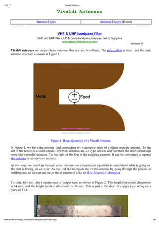
  • 1. 7/16/12 Vivaldi Antenna VvliAtna iad nens Antenna Types Antenna Theory (Home) VHF & UHF bandpass filter VHF and UHF filters, LC & cavity bandpass, lowpass, notch, highpass www.anatechelectronics.com Vivaldi antennas are simple planar antennas that are very broadband. The polarization is linear, and the basic antenna structure is shown in Figure 1: Figure 1. Basic Geometry of a Vivaldi Antenna. In Figure 1, we have the antenna feed connecting two symmetric sides of a planar metallic antenna. To the left of the feed is is a short-circuit. However, antennas are RF-type devices and therefore the short-circuit acts more like a parallel inductor. To the right of the feed is the radiating element. It can be considered a tapered slot antenna or an aperture antenna. At this stage we could go through some moronic and complicated equations to understand what is going on. But that is boring, so we won't do that. I'd like to explain the vivaldi antenna by going through the process of building one, so we can see that is the evolution of a slot or IFA (Inverted-F Antenna). To start, let's just take a square area of copper tape, as shown in Figure 2. The length (horizontal dimension) is 84 mm, and the height (vertical dimension) is 54 mm. This is just a flat sheet of copper tape sitting on a piece of FR4: www.antenna-theory.com/antennas/aperture/vivaldi.php 1/9
  • 2. 7/16/12 Vivaldi Antenna Figure 2. A Rectangular Slab of Copper. Now, to start, I'm going to cut a slot out of the slab in Figure 2. The slot will be about 80mm long, and about 5-10mm wide, as shown in Figure 3: www.antenna-theory.com/antennas/aperture/vivaldi.php 2/9
  • 3. 7/16/12 Vivaldi Antenna Figure 3. Cutting a Slot out of a Rectangular Slab of Copper. This slot is not an antenna yet, because there is no feed. So I grab a standard coaxial cable with an SMA connection and solder it about 38mm from the end of the slot, as shown in Figure 4: Figure 4. Adding the Feed to Our Antenna. In Figure 4, I've soldered the center conductor of the coaxial cable to one side of the slot, and the ground (shield or outside) of the cable to the other side. I also solder the cable along the length to the antenna structure. This keeps the cable itself from being a separate radiator - since it is part of the antenna structure the electric currents don't care if they are flowing on the cable or the antenna. This is similar to a balun. USB Spectrum Analyzer SA44B 1Hz to 4.4GHz, -151dBm, $919 includes AM, FM, SSB, and CW demod www.SignalHound.com I hooked the antenna of Figure 4 to a Vector Network Analyzer (VNA) and measured the VSWR of the antenna from 500 MHz to 6 GHz. This is plotted in Figure 5: www.antenna-theory.com/antennas/aperture/vivaldi.php 3/9
  • 4. 7/16/12 Vivaldi Antenna Figure 5. The VSWR for the Antenna of Figure 4. In Figure 5, we see that our antenna, which is pretty simple, already has a few resonances. When I say resonance here, I mean a region where the VSWR dips and then goes back up. The reason I call this is a resonance, is that there is no loss in my circuit - no matching components, resistive devices, loss materials, etc. Hence, if the VSWR drops, then energy is probably being radiated away (it is, but I'll get to that later). From Figure 5, we see that we have 3 frequency bands where our antenna acts somewhat like an antenna: around 1 GHz From 2.5-4 GHz At about 5.8 GHz This is interesting in my opinion. All we really did was feed a metallic structure, and we get a bunch of radiation. This is pretty cool, and it shows that nature wants things to radiate. From Maxwell's Equations, we know that if we can just get electric currents or voltage to add in phase, we will have radiation. And that's cool. Our antenna is a little bit like an IFA at this point, a little bit like a slot antenna, and also a bit like a dipole antenna. But never mind too much analysis right now. Let's say we shortened the slot of our antenna, so that the feed is now 18mm from the left edge, as shown in Figure 6: Figure 6. The same antenna, but with a shorter slot. The resulting VSWR of our antenna is now shifted up in frequency - we should expect this since our slot is now shorter. This is shown in Figure 7: www.antenna-theory.com/antennas/aperture/vivaldi.php 4/9
  • 5. 7/16/12 Vivaldi Antenna Figure 7. The VSWR curves for the Original Antenna (black) and the Antenna in Figure 6 (blue). We can learn something by looking at Figure 7. I expected the slot shortening to increase the frequency of the resonances. However, only the 3 GHz resonance increased in frequency. This tells me that the slot mode of radiation is responsible for the 3.5 GHz resonance. The 1 GHz resonance did not shift - however, it did get deeper, which indicates the antenna has a better impedance match with a shorter slot. Shortening the slot has the effect of decreasing the shunt inductance that is the short circuit to the left of the feed. In Figure 6, the antenna resembles a dipole antenna that has the short circuit to the left (the inductive path). Hence, by shortening the slot, I basically improved the impedance matching of the dipole antenna mode - and I also now know that the dipole antenna mode occurs at 1 GHz, and the slot/ifa antenna mode occurs at about 3.5 GHz. The higher resonance had a slight downshift, but really it appears that the resonance got broader as well. Hence I suspect this is also a slot antenna mode, but this relies more on the slot to the right of the feed, as the very large inductance to the left of the feed basically doesn't matter at 6 GHz (this is because the impedance of an inductor is very high and basically an open circuit for high frequencies). The preceeding 3 paragraphs is exactly how antenna engineers think. Now, the morons in the university would spend all year trying to think up a crappy equation - and they would get it wrong. Not only that, these people have never put an antenna in a product, so don't have a clue. If you can make a change to an antenna, and observe the changes in resonances and explain them, then you understand the antenna. If not you might as well work in the defense industry doing nothing with your life. Now, back to the design. We know that more volume for antennas generally means more bandwidth. However, we have a little too much ground plane here - and that means a lot of capacitance. And capacitance kills your bandwidth and isn't good for radiation. So right now, we'll taper the slot, or flare the aperture as shown in Figure 8: www.antenna-theory.com/antennas/aperture/vivaldi.php 5/9
  • 6. 7/16/12 Vivaldi Antenna Figure 8. A Tapered Slot Antenna. The VSWR of this antenna is measured and plotted with the other curves in Figure 9: Figure 9. VSWR of the Tapered Slot Antenna (in Fig 8). In Figure 9, the green curve is the VSWR of the tapered slot antenna of Figure 8. We see some nice things happened - the two resonances at 3.5 GHz and 5.8 GHz start to blend together, giving a very large bandwidth. In addition, the lowband (1 GHz) resonance also became broader band and better matched, as you can see from the lower and broader VSWR. This means our tapering of the slot made things much better from a radiation perspective. Since this was a pleasant change, let's taper both sides as shown in Figure 10: www.antenna-theory.com/antennas/aperture/vivaldi.php 6/9
  • 7. 7/16/12 Vivaldi Antenna Figure 10. Dual Tapered Slot - The Vivaldi Antenna. The VSWR of this antenna is plotted in Figure 11, with the others: Figure 11. VSWR of the Vivaldi Antenna (in red). Figure 11 shows that the overall bandwidth of the Vivaldi antenna increased (the impedance matching was www.antenna-theory.com/antennas/aperture/vivaldi.php 7/9
  • 8. 7/16/12 Vivaldi Antenna Figure 11 shows that the overall bandwidth of the Vivaldi antenna increased (the impedance matching was better over a wider range). We also see the lowband resonance increase in frequency slightly (i.e. the 1 GHz resonance shifts up). This is due to less capacitive loading (capacitive loading, or capacitance in the antenna structure tends to shift resonances down in frequency). We have now constructed a Vivaldi Antenna. We see that is has a low resonance and a very broad higher frequency resonance. We suspect very strongly that this radiates (since there is no other losses in the structure). However, to be sure, we should measure the antenna efficiency in an anechoic chamber. This is done and is plotted in Figure 12: Figure 12. Antenna Efficiency for the Vivaldi. From Figure 12, we see that the Vivaldi antenna I threw together in Figure 10 has very broad bandwidth and very high efficiency. This shows that our resonances in the VSWR plots are indeed due to radiation resistance - and not loss. The direction of peak radiation is frequency dependent. For the low frequency band of radiation, I stated that the antenna acted as a dipole type antenna. In this case, the direction of peak radiation is directly into or out of the page as viewed in Figure 10. For the higher frequency band of radiation (3.5-6 GHz), the antenna is using the aperture to radiate. In this case, the direction of peak radiation is to the left as seen in Figure 10. Finally, you may also see Vivaldi antenna with odd shaped slots cut out of the left side of the feed as shown in Figure 13: www.antenna-theory.com/antennas/aperture/vivaldi.php 8/9
  • 9. 7/16/12 Vivaldi Antenna Figure 13: Figure 13. Vivaldi with a Loop to the Left. The primary purpose of altering the short-circuit path to the left of the feed is for antenna tuning purposes (i.e. impedance matching). There is no real radiation that is added via adding the circular cut shown in Figure 13, but it does give the antenna designer more freedom in optimizing the VSWR or tuning of the antenna. CEL/Renesas RF Devices Quality and Reliability Formerly NEC Electronics www.cel.com Types of Antennas Antenna Theory (Home) This page on vivaldi antennas is copyrighted. No portion can be reproduced except by permission from the author. Copyright antenna-theory.com, 2009-2012. www.antenna-theory.com/antennas/aperture/vivaldi.php 9/9