6. GroutGrout
• A “high performance” mortarA “high performance” mortar
• High slump easier to flowHigh slump easier to flow
• Reinforcing in cells and betweenReinforcing in cells and between
wythes of masonrywythes of masonry
• For adhesion (epoxy grout)For adhesion (epoxy grout)
• For bearing (under concrete andFor bearing (under concrete and
steel columns) to level andsteel columns) to level and
transfer loadstransfer loads
9. Post-tensioning : threaded high-
strength bars joined with
threaded couplers. At the base
the bar is anchored to a
threaded insert epoxied into a
drilled hole in the concrete
foundation. At the top, the bar
passes through a steel plate. the
nut at the top end of the bar is
tightened, the masonry wall is
placed in greater compression..
10. • Composite WallsComposite Walls
• More economicMore economic
• Multiple wythesMultiple wythes
• Stone/brick on exteriorStone/brick on exterior
• CMU (back-up) on interiorCMU (back-up) on interior
• Joined together with reinforcingJoined together with reinforcing
• Grout or mortar between wythesGrout or mortar between wythes
11. • Cavity WallsCavity Walls
• Exterior wallsExterior walls
• Two wythesTwo wythes
• Inner wythe for structural supportInner wythe for structural support
• Outer wythe for veneerOuter wythe for veneer
• Resists moisture and heat transferResists moisture and heat transfer
• Wythes separated byWythes separated by airspaceairspace
• Insulation & DrainageInsulation & Drainage
• Wythes joined with masonryWythes joined with masonry tiesties
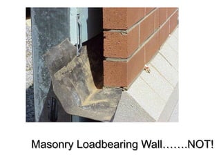
13. Monadnock building,Monadnock building,
18911891
Last unreinforced masonry load
bearing highrise structure built
based on traditional “rules”
215 ft high
16 story
6 ft thick wall at base
Interior cast iron frame
Very small ground floor spaces
14. Texas School Book DepositoryTexas School Book Depository
Loadbearing brick masonry walls
Internal timber columns and beams
Type 3 – Ordinary Construction
31. Anchorage & TiesAnchorage & Ties
• Holds masonry to wallHolds masonry to wall
• Ties wythes of masonryTies wythes of masonry
• to one anotherto one another
• To supporting substrates (wood, concrete, steel)To supporting substrates (wood, concrete, steel)
• Must resist lateral loads but…..Must resist lateral loads but…..
• Must allow for horizontal and vertical movementMust allow for horizontal and vertical movement
• Usually hot-dipped galvanized coated or stainless steelUsually hot-dipped galvanized coated or stainless steel
• Many different methods & types usedMany different methods & types used
32. Reinforcing & AnchorageReinforcing & Anchorage
• Brick & Stone VeneerBrick & Stone Veneer
AnchorageAnchorage
• Anchor brick to “back-upAnchor brick to “back-up
wallwall
• Typically - galvanizedTypically - galvanized
wirewire
• Cast in joint, or “nailed” toCast in joint, or “nailed” to
surfacesurface
33.
34. FlashingFlashing
Prevents and directs moisture/water outPrevents and directs moisture/water out
• ExternalExternal
• To prevent moisture penetration atTo prevent moisture penetration at
• Wall intersectionsWall intersections
• Wall/roof intersectionsWall/roof intersections
• Changes in materialChanges in material
• InternalInternal
• Directs moisture in the wall out throughDirects moisture in the wall out through
weep holesweep holes
35. External FlashingExternal Flashing
• TypesTypes
• Cap flashing -Cap flashing -
• To p o f wallsTo p o f walls
• Edg e o f ro o fsEdg e o f ro o fs
• Counter flashingCounter flashing
• Wall/ ro o f inte rse ctio nWall/ ro o f inte rse ctio n
• Ofte n two pie ce s - o ne in wall/ o ne attache dOfte n two pie ce s - o ne in wall/ o ne attache d
37. FlashingFlashing
Internal FlashingInternal Flashing
• ““Through Wall”Through Wall” oror
Concealed FlashingConcealed Flashing
• Continuous sheet ofContinuous sheet of
Copper, plastic,Copper, plastic,
rubber/bituminousrubber/bituminous
• Attached to backup wallAttached to backup wall
& run through to the& run through to the
outside of the masonryoutside of the masonry
• Collects waterCollects water
• that has penetrated wallthat has penetrated wall
• Allows it drainAllows it drain
38. Internal FlashingInternal Flashing
• Drainage Through “Weeps”Drainage Through “Weeps”
• Placed 24 to 32 in o.c.Placed 24 to 32 in o.c.
• Rope, plastic, metal, raked or full head ventRope, plastic, metal, raked or full head vent
• PlacementPlacement
• Bottom of wall cavityBottom of wall cavity
• Interruptions of cavityInterruptions of cavity
• Over doors / windowsOver doors / windows
• Window sillsWindow sills
• Shelf anglesShelf angles
39. Flashing MaterialsFlashing Materials
• CopperCopper (reacts with mortar)(reacts with mortar)
• LeadLead (malleable)(malleable)
• Lead Coated CopperLead Coated Copper
• AluminumAluminum (reacts with mortar)(reacts with mortar)
• MembranesMembranes
• Bituminous and rubber membranes more popularBituminous and rubber membranes more popular
• do not corrodedo not corrode
• more flexiblemore flexible
• easier to installeasier to install
• Synthetic Rubber membranesSynthetic Rubber membranes
40. WeepingWeeping
• WickWick
• Rope laid in the mortar jointRope laid in the mortar joint
• Should be removedShould be removed
after mortar sets upafter mortar sets up
• TubeTube
• 3/8” diameter tubes laid in3/8” diameter tubes laid in
the mortar jointthe mortar joint
• Can be removed or leftCan be removed or left
in jointin joint
• Raked Head JointRaked Head Joint
• Mortar let out of the headMortar let out of the head
jointjoint
• Most effective weepMost effective weep
jointjoint
41. Insulation in CMU cells Insulation in Cavity
Insulation in CavityExternal Insulation
43. Control JointsControl Joints
• Controls movement for a single materialControls movement for a single material
• Lines of weakness that cause cracking to occurLines of weakness that cause cracking to occur
along that linealong that line
• Concrete walksConcrete walks
• SlabsSlabs
45. • EfflorescenceEfflorescence
• White “chalky”White “chalky”
substance on the facesubstance on the face
of masonryof masonry
• Usually salts inUsually salts in
masonry or mortar leftmasonry or mortar left
from migratingfrom migrating
moisturemoisture
• Indicates thatIndicates that
moisture is presentmoisture is present
• Normal for newNormal for new
constructionconstruction
• In existingIn existing
construction, it usuallyconstruction, it usually
means a leakmeans a leak
46.
47. • SpallingSpalling
• Physical failure (breakage) of thePhysical failure (breakage) of the
masonry material or mortarmasonry material or mortar
• Deterioration from moisture in theDeterioration from moisture in the
wallwall
• Damage from freeze/thaw cyclesDamage from freeze/thaw cycles
48. • Tuck PointingTuck Pointing
• Partial removal of anPartial removal of an
existing mortar jointexisting mortar joint
and replacementand replacement
with new mortarwith new mortar
• For severelyFor severely
damaged mortardamaged mortar
jointsjoints
• May be for aestheticMay be for aesthetic
or functional reasonsor functional reasons
• Mortar removed to aMortar removed to a
third of the widththird of the width
• New mortar put backNew mortar put back
to seal jointto seal joint
50. Wide Flange DesignationsWide Flange Designations
W 12 X 26W 12 X 26
W = Wide Flange DesignationW = Wide Flange Designation
12 = Nominal Depth (inches)12 = Nominal Depth (inches)
26 = Weight (lbs.) per foot26 = Weight (lbs.) per foot
W12x26 - 12’-0” long weights:W12x26 - 12’-0” long weights:
12’ x 26#/lf = 312#12’ x 26#/lf = 312#
Depth
51. Steel AnglesSteel Angles
USESUSES
Short beamsShort beams supporting light loadssupporting light loads
EX - LintelsEX - Lintels
ConnectorsConnectors
Veneer / Skin SupportVeneer / Skin Support
Edge support (edge angle)Edge support (edge angle)
Diagonal bracingDiagonal bracing
52. Steel Angle DesignationsSteel Angle Designations
L 4 X 4 X 1/2L 4 X 4 X 1/2
L = Angle DesignationL = Angle Designation
4 X 4 = Size of the legs4 X 4 = Size of the legs (inches)(inches)
1/2 = Thickness of the legs1/2 = Thickness of the legs
(inches)(inches)
NOTE: Legs can be equal or unequalNOTE: Legs can be equal or unequal
Size
Thickness
53. Channels (C Shaped)Channels (C Shaped)
• UsesUses
• Truss members, bracing, lintels, etc.Truss members, bracing, lintels, etc.
• DesignationsDesignations
C 9 X 13.4C 9 X 13.4
C = Channel DesignationC = Channel Designation
9 = Nominal Depth (inches)9 = Nominal Depth (inches)
13.4 = Weight / ft. (lbs.)13.4 = Weight / ft. (lbs.)
Depth
54. Open Web Steel JoistsOpen Web Steel Joists
• Mass produced steel trussesMass produced steel trusses
• Common UsesCommon Uses
• Floor SupportFloor Support
• Roof SupportRoof Support
• Joist Spacing Depends on;Joist Spacing Depends on;
• LoadLoad
• Span capability of deckSpan capability of deck
• Typically 2 to 10 feetTypically 2 to 10 feet
Spans; K-series (up to 60’), LH(Longspan) to 96’, DLH(Deep Longspan) to 144’
Joint Reinforcing
PLACED IN THE “BED” JOINT
TYPICALLY FOR CMU
INCREASED WALL STRENGTH
TWO TYPES - TYPICAL
TYPICALLY - GALVANIZED WIRE
OFTEN PLACED EVERY OTHER COURSE
Ladder
LOOKS LIKE A LADDER
Truss
LOOKS LIKE A TRUSS
Brick & Stone Veneer Anchorage
ANCHOR BRICK TO “BACK-UP WALL
TYPICALLY - GALVANIZED WIRE
CAST IN JOINT, OR “NAILED” TO SURFACE
Size Range
Depth; 4” to 36”
Weight; 9#/ft to 730#/ft
Uses - Beams & Columns
Proportions - Shape
Tall &Narrow - Beams
Square - Columns & Piles
USES
Short “beams” supporting light loads
EX - Lintels
Connectors
Diagonal bracing
“Mass” produced steel trusses
SERIES OF SMALL ANGLES, ROD, ETC.
Common Uses
Floor Support
Roof Support
Joist Spacing Depends on;
Load
Span capability of decking
Typically 2 to 10 feet