SlideShare una empresa de Scribd logo
1 de 70
Analogue Modulation – Amplitude Modulation v c ( t ) =  V c  cos (  c t ), peak amplitude =  V c , carrier frequency   c  radians per second. Since   c  = 2  f c , frequency =  f c  Hz where  f c  =  1/ T . Consider a 'sine wave' carrier. Amplitude Modulation AM In AM, the modulating signal (the message signal)  m ( t ) is 'impressed' on to the  amplitude of the carrier.
Message Signal  m ( t ) In general  m ( t ) will be a band of signals, for example speech or video signals. A  notation or convention to show baseband signals for  m ( t ) is shown below
Message Signal  m ( t ) In general  m ( t ) will be band limited. Consider for example, speech via a microphone.  The envelope of the spectrum would be like:
Contoh
Contoh
Message Signal  m ( t ) In order to make the analysis and indeed the testing of AM systems easier, it is common to make  m ( t ) a test signal,  i.e.  a signal with a constant amplitude and frequency given by
Schematic Diagram for Amplitude Modulation V DC   is a variable voltage, which can be set between 0 Volts and + V  Volts. This  schematic diagram is very useful; from this all the important properties of AM and  various forms of AM may be derived.
Equations for AM From the diagram  where  V DC  is the DC voltage that can be varied. The equation is in the form Amp cos   c t  and we may 'see' that the amplitude is a function of  m ( t ) and  V DC . Expanding the equation we get:
Equations for AM Now let  m ( t ) =  V m   cos   m t, i.e.  a 'test' signal, Using the trig identity   we have   Components: Carrier upper sideband USB lower sideband LSB Amplitude: V DC V m /2 V m /2 Frequency:  c    c  +   m    c  –   m f c   f c  + f m   f c  + f m This equation represents  Double Amplitude Modulation – DSBAM
Spectrum and Waveforms The following diagrams  represent the spectrum of the  input  signals,  namely ( V DC  + m ( t )),  with  m ( t ) =  V m   cos   m t ,  and the carrier  cos   c t  and corresponding  waveforms.
Spectrum and Waveforms The above are input signals. The diagram below shows the spectrum and  corresponding waveform of the  output  signal, given by
Spektrum 2 sisi
Double Sideband AM, DSBAM The component at the output at the carrier frequency  f c  is shown as a broken line with amplitude  V DC  to show that the amplitude depends on  V DC . The structure of the  waveform will now be considered in a little more detail. Waveforms Consider again the diagram V DC  is a variable DC offset added to the message;  m ( t ) =  V m  cos   m t
Double Sideband AM, DSBAM This is multiplied by a carrier, cos   c t . We effectively multiply ( V DC  + m ( t )) waveform by +1, -1, +1, -1, ... The product gives the output signal
Double Sideband AM, DSBAM
Modulation Depth  Consider again the equation   , which may be written as   The ratio is  defined as the  modulation depth ,  m ,  i.e.   Modulation Depth   From an oscilloscope display the modulation depth for Double Sideband AM may be  determined as follows:
Modulation Depth 2 2 E max  =  maximum peak-to-peak of waveform 2 E min  =  minimum peak-to-peak of waveform   Modulation Depth  This may be shown to equal  as follows:  = =
Double Sideband Modulation 'Types' ,[object Object],[object Object],[object Object],[object Object],[object Object]
Graphical Representation of Modulation Depth and Modulation Types.
Graphical Representation of Modulation Depth and Modulation Types 2.
Graphical Representation of Modulation Depth and Modulation Types 3 Note then that  V DC   may be set to give  the modulation depth and modulation type. DSBAM V DC  >> V m ,  m    1 DSB Dim C  0 <  V DC  < V m ,  m >  1 (1 <  m  <   ) DSBSC V DC  =  0,  m =   The spectrum for the 3 main types of  amplitude modulation are summarised
Bandwidth Requirement for DSBAM In general, the message signal  m ( t ) will not be a single 'sine' wave, but a band of frequencies  extending up to  B  Hz as shown Remember – the 'shape' is used for convenience to distinguish low frequencies from high  frequencies in the baseband signal.
Bandwidth Requirement for DSBAM ,[object Object],[object Object],[object Object],[object Object],[object Object],[object Object],[object Object],[object Object],[object Object]
Power Considerations in DSBAM  Remembering that Normalised Average Power = ( V RMS ) 2  =  we may tabulate for AM components as follows: Total Power  P T  =  Carrier Power  P c   + P USB + P LSB Power Power V DC Amplitude pk LSB USB Carrier Component
Power Considerations in DSBAM  From this we may write two equivalent equations for the total power  P T , in a DSBAM signal The carrier power   and or i.e. Either of these forms may be useful. Since both USB and LSB contain the same information a  useful ratio which shows the proportion of 'useful' power to total power is
Power Considerations in DSBAM  For DSBAM ( m     1), allowing for  m ( t ) with a dynamic range, the average value of  m   may be assumed to be  m  = 0.3 Hence, on average only about 2.15% of the total power transmitted may be regarded  as 'useful' power. (   95.7% of the total power is in the carrier!) Hence,  Even for a maximum modulation depth of  m  = 1 for DSBAM the ratio  i.e.  only 1/6th of the total power is 'useful' power (with 2/3 of the total power in the  carrier).
Grafik
Example Suppose you have a  portable  (for example you carry it in your ' back pack') DSBAM transmitter  which needs to transmit an average power of 10 Watts in each sideband when modulation depth  m  = 0.3. Assume that the transmitter is powered by a 12 Volt battery. The total power will be  where  = 10 Watts,  i.e.   = 444.44 Watts   Hence, total power  P T  =  444.44 + 10 + 10 = 464.44 Watts.  Hence, battery current (assuming ideal transmitter) = Power / Volts =  i.e.  a large and heavy 12 Volt battery.   amps! Suppose we could remove one sideband and the carrier, power transmitted would be  10 Watts,  i.e.  0.833 amps from a 12 Volt battery, which is more reasonable for a  portable radio transmitter.
Single Sideband Amplitude Modulation One method to produce signal sideband (SSB) amplitude modulation is to produce  DSBAM, and pass the DSBAM signal through a band pass filter, usually called a  single sideband filter, which passes one of the sidebands as illustrated in the diagram  below. The type of SSB may be SSBAM (with a 'large' carrier component), SSBDimC or  SSBSC depending on  V DC  at the input. A sequence of spectral diagrams are shown  on the next page.
Single Sideband Amplitude Modulation
Single Sideband Amplitude Modulation Note that the bandwidth of the SSB signal  B  Hz is half of the DSB signal bandwidth.  Note also that an ideal SSB filter response is shown. In practice the filter will not be  ideal as illustrated. As shown, with practical filters some part of the rejected sideband (the LSB in this  case) will be present in the SSB signal. A method which eases the problem is to  produce SSBSC from DSBSC and then add the carrier to the SSB signal.
Single Sideband Amplitude Modulation
Single Sideband Amplitude Modulation with  m ( t ) =  V m  cos   m t , we may write: The SSB filter removes the LSB (say) and the output is Again, note that the output may be SSBAM,  V DC  large SSBDimC,  V DC   small SSBSC,  V DC  = 0 For SSBSC, output signal =
Power in SSB From previous discussion, the total power in the DSB signal is  Hence, if  P c  and  m  are known, the carrier power and power in one sideband may be  determined. Alternatively, since SSB signal =  then the power in SSB signal (Normalised Average Power) is  Power in SSB signal =   = for DSBAM.
Demodulation of Amplitude Modulated Signals ,[object Object],[object Object],[object Object]
Envelope or Non-Coherent Detection This is obviously simple, low cost. But the AM input  must be  DSBAM with  m  << 1,  i.e.   it does not demodulate DSBDimC, DSBSC or SSBxx. An envelope detector for AM is shown below:
Large Signal Operation For large signal inputs, (   Volts) the diode is switched  i.e.  forward biased    ON, reverse  biased    OFF, and acts as a half wave rectifier. The 'RC' combination acts as a 'smoothing  circuit' and the output is  m ( t ) plus 'distortion'. If the modulation depth is > 1, the distortion below occurs
Small Signal Operation – Square Law Detector For small AM signals (~ millivolts) demodulation depends on the diode square law  characteristic. The diode characteristic is of the form  i ( t ) =  av + bv2 + cv3 + ... , where  i.e.  DSBAM signal.
Small Signal Operation – Square Law Detector = = = 'LPF' removes components. Signal out =  i.e.  the output contains  m ( t ) i.e.
Synchronous or Coherent Demodulation A synchronous demodulator is shown below This is relatively more complex and more expensive. The Local Oscillator (LO) must be  synchronised or coherent,  i.e.  at the same frequency and in phase with the carrier in the AM input signal. This additional requirement adds to the complexity and the cost. However, the AM input may be  any  form of AM,  i.e.  DSBAM, DSBDimC, DSBSC or  SSBAM, SSBDimC, SSBSC. (Note – this is a 'universal' AM demodulator and the  process is similar to correlation – the LPF is similar to an integrator).
Synchronous or Coherent Demodulation If the AM input contains a small or large component at the carrier frequency, the LO  may be derived from the AM input as shown below.
Synchronous (Coherent) Local Oscillator If we assume zero path delay between the modulator and demodulator, then the ideal  LO signal is cos(  c t ). Note – in general the will be a path delay, say   , and the LO  would then be cos(  c ( t –   ),  i.e.  the LO is synchronous with the carrier implicit in the received signal. Hence for an ideal system with zero path delay Analysing this for a DSBAM input =
Synchronous (Coherent) Local Oscillator V X  =  AM input x LO = We will now examine the signal spectra from 'modulator to V x' = =
Synchronous (Coherent) Local Oscillator (continued on next page)
Synchronous (Coherent) Local Oscillator Note – the AM input has been 'split into two' – 'half' has moved or shifted up to   and half shifted down to baseband,   and  and  and  and  and  and
Synchronous (Coherent) Local Oscillator The LPF with a cut-off frequency    f c  will pass only the baseband signal i.e.  In general the LO may have a frequency offset,   , and/or a phase offset,   , i.e. ,[object Object],[object Object],[object Object]
1. Double Sideband (DSB) AM Inputs The equation for DSB is  diminished carrier or suppressed carrier to be set.  where VDC allows full carrier (DSBAM), Hence, Vx = AM Input x LO Since
1. Double Sideband (DSB) AM Inputs The LPF with a cut-off frequency    f c  Hz will remove the components at 2  c  (i.e.  components above   c ) and hence Obviously, if  and   we have, as previously  Consider now if    is equivalent to a few Hz offset from the ideal LO. We may then  say The output, if speech and processed by the human brain may be intelligible, but  would include a low frequency 'buzz' at   , and the message amplitude would  fluctuate. The requirement    = 0 is necessary for DSBAM.
1. Double Sideband (DSB) AM Inputs Consider now if    is equivalent to a few Hz offset from the ideal LO. We may then  say The output, if speech and processed by the human brain may be intelligible, but would  include a low frequency 'buzz' at   , and the message amplitude would fluctuate. The  requirement     = 0 is necessary for DSBAM. Consider now that    = 0 but       0, i.e. the frequency is correct at   c  but there is a phase offset. Now we have  'cos(  )' causes fading (i.e. amplitude reduction) of the output.
1. Double Sideband (DSB) AM Inputs The 'V DC ' component is not important, but consider for m(t), ,[object Object],(90 0 ),   i.e.   (180 0 ),   ,[object Object],i.e.   The phase inversion if    =    may not be a problem for speech or music, but it may be  a problem if this type of modulator is used to demodulate PRK  However, the major problem is that as    increases towards  the signal strength  output gets weaker (fades) and at  the output is zero
1. Double Sideband (DSB) AM Inputs If the phase offset varies with time, then the signal fades in and out. The variation of  amplitude of the output, with phase offset    is illustrated below Thus the requirement for    = 0 and    = 0 is a 'strong' requirement for DSB amplitude  modulation.
2. Single Sideband (SSB) AM Input The equation for SSB with a carrier depending on V DC  is i.e. assuming  Hence  =
2. Single Sideband (SSB) AM Input The LPF removes the 2  c  components and hence Note, if    = 0 and    = 0,  ,i.e.   has been recovered. Consider first that       0, e.g. an offset of say 50Hz. Then If m(t) is a signal at say 1kHz, the output contains a signal a 50Hz, depending on V DC   and the 1kHz signal is shifted to 1000Hz -  50Hz = 950Hz.
2. Single Sideband (SSB) AM Input The spectrum for V out  with    offset is shown Hence, the effect of the offset    is to shift the baseband output, up or down, by   .  For speech, this shift is not serious (for example if we receive a 'whistle' at 1kHz and  the offset is 50Hz, you hear the whistle at 950Hz (   = +ve) which is not very  noticeable. Hence, small frequency offsets in SSB for speech may be tolerated.  Consider now that    = 0,    = 0, then
2. Single Sideband (SSB) AM Input ,[object Object],[object Object]
Comments ,[object Object],[object Object],[object Object],[object Object],[object Object],[object Object],[object Object],[object Object]
Phase Shift Method for SSB Generation The diagram below shows the Phase Shift Method for generating SSBSC f m  and f c  denote phase shifts at the message frequency (f m ) and the carrier  frequency (f c ).
Phase Shift Method for SSB Generation Solving for V out  in general terms  i.e.   Since  The actual form of the modulation at the output will depend on the phase shifts f m   and f c .
Phase Shift Method for SSB Generation Consider V out  when  (i.e.90 0 )  Since  then  When  fm = 90 0  and  fc = 90 0  the output is Single Sideband Suppressed Carrier –  Lower Sideband. , i.e. SSBSC/LSB.
Phase Shift Method for SSB Generation Consider   V out   when  ,  and since  then   i.e. SSBSC/USB. When  f m  = 90 0  and  f c  = -90 0  the output is Single Sideband  Suppressed Carrier – Upper Sideband. Note – for m(t) as a band of signals, the phase shift f m  must be the same e.g.   /2 or  90 0  at all frequencies.
Exercise 1) When f m  = 0 and  f c  = 0 show that  2) When  f m  = 0 and  f c  =    show that V out  = 0
Quadrature Modulation A variation on the Phase Shift Method is shown below In this form of the method, 2 different message signals m 1 (t) and m 2 (t) are input.
Quadrature Modulation The carrier  is phase shifted by 90 0  to give  The two carriers,  and   are in phase quadrature (orthogonal).  Quadrature Modulation or Quadrature Multiplexing  and as Independent Sideband ISB. The process is described as Clearly,  .
Quadrature Modulation Each 'term' in the output is a DSBSC signal occupying the same bandwidth, but  phase shifted by 90 0  relative to each other
Quadrature Modulation Demodulation will require synchronous demodulators as shown below.
Quadrature Modulation Clearly   Since   Since the LPF with cut-off frequency = f c , the output  Similarly,  Since Again, LPF removes the '2wc components, i.e.
Quadrature Modulation This type of modulation/multiplexing is used in radio systems, television and as a  form of stereo multiplexing for AM radio.
Vestigial Sideband Modulation Some signals, such as TV signals contain low frequencies, or even extend down to DC. When DSB modulated we have
Vestigial Sideband Modulation It is now impossible to produce SSB, because the SSB filter would need to be ideal,  as shown above. In practice the filter is as below The signal produced is called vestigial sideband, it contains the USB and a 'vestige'  of the lower sideband. The BPF design is therefore less stringent. When demodulated  the baseband signal is the sum of the USB and the vestige of the LSB
Vestigial Sideband Modulation Hence the original baseband signal. VSB is used in TV systems.

Más contenido relacionado

La actualidad más candente

Single Sideband Suppressed Carrier (SSB-SC)
Single Sideband Suppressed Carrier (SSB-SC)Single Sideband Suppressed Carrier (SSB-SC)
Single Sideband Suppressed Carrier (SSB-SC)Ridwanul Hoque
 
Frequency modulation
Frequency modulationFrequency modulation
Frequency modulationAkanksha_Seth
 
Fir filter design (windowing technique)
Fir filter design (windowing technique)Fir filter design (windowing technique)
Fir filter design (windowing technique)Bin Biny Bino
 
Angle modulation
Angle modulationAngle modulation
Angle modulationUmang Gupta
 
Transmission line, single and double matching
Transmission line, single and double matchingTransmission line, single and double matching
Transmission line, single and double matchingShankar Gangaju
 
AMPLITUDE MODULATION & DEMODULATION TECHNIQUE
AMPLITUDE MODULATION & DEMODULATION TECHNIQUEAMPLITUDE MODULATION & DEMODULATION TECHNIQUE
AMPLITUDE MODULATION & DEMODULATION TECHNIQUEIMTIAZ ALI AHMED
 
FM Demodulation.ppt
FM Demodulation.pptFM Demodulation.ppt
FM Demodulation.pptArfaQasim1
 
M ary psk modulation
M ary psk modulationM ary psk modulation
M ary psk modulationAhmed Diaa
 
Amplitute modulation
Amplitute modulationAmplitute modulation
Amplitute modulationZunAib Ali
 
AM and FM Transmitters and receivers
AM and FM Transmitters and receiversAM and FM Transmitters and receivers
AM and FM Transmitters and receiversKavitaGiri5
 
Unit-I Characteristics of opamp
Unit-I Characteristics of opampUnit-I Characteristics of opamp
Unit-I Characteristics of opampDr.Raja R
 
Analog communication
Analog communicationAnalog communication
Analog communicationPreston King
 
NOISE IN Analog Communication Part-1.ppt
NOISE IN Analog Communication  Part-1.pptNOISE IN Analog Communication  Part-1.ppt
NOISE IN Analog Communication Part-1.pptAshishChandrakar12
 
Am transmitter
Am transmitterAm transmitter
Am transmitterAJAL A J
 
Modulation techniques
Modulation techniquesModulation techniques
Modulation techniquesSathish Kumar
 
Pulse amplitude modulation & demodulation
Pulse amplitude modulation & demodulationPulse amplitude modulation & demodulation
Pulse amplitude modulation & demodulationVishal kakade
 
single stage amplifier Unit 5 AMVLSI
single stage amplifier Unit 5 AMVLSIsingle stage amplifier Unit 5 AMVLSI
single stage amplifier Unit 5 AMVLSIHarsha Raju
 

La actualidad más candente (20)

Single Sideband Suppressed Carrier (SSB-SC)
Single Sideband Suppressed Carrier (SSB-SC)Single Sideband Suppressed Carrier (SSB-SC)
Single Sideband Suppressed Carrier (SSB-SC)
 
Angle modulation
Angle modulationAngle modulation
Angle modulation
 
Frequency modulation
Frequency modulationFrequency modulation
Frequency modulation
 
Fir filter design (windowing technique)
Fir filter design (windowing technique)Fir filter design (windowing technique)
Fir filter design (windowing technique)
 
Angle modulation
Angle modulationAngle modulation
Angle modulation
 
Power amplifiers
Power amplifiersPower amplifiers
Power amplifiers
 
Transmission line, single and double matching
Transmission line, single and double matchingTransmission line, single and double matching
Transmission line, single and double matching
 
AMPLITUDE MODULATION & DEMODULATION TECHNIQUE
AMPLITUDE MODULATION & DEMODULATION TECHNIQUEAMPLITUDE MODULATION & DEMODULATION TECHNIQUE
AMPLITUDE MODULATION & DEMODULATION TECHNIQUE
 
FM Demodulator
FM DemodulatorFM Demodulator
FM Demodulator
 
FM Demodulation.ppt
FM Demodulation.pptFM Demodulation.ppt
FM Demodulation.ppt
 
M ary psk modulation
M ary psk modulationM ary psk modulation
M ary psk modulation
 
Amplitute modulation
Amplitute modulationAmplitute modulation
Amplitute modulation
 
AM and FM Transmitters and receivers
AM and FM Transmitters and receiversAM and FM Transmitters and receivers
AM and FM Transmitters and receivers
 
Unit-I Characteristics of opamp
Unit-I Characteristics of opampUnit-I Characteristics of opamp
Unit-I Characteristics of opamp
 
Analog communication
Analog communicationAnalog communication
Analog communication
 
NOISE IN Analog Communication Part-1.ppt
NOISE IN Analog Communication  Part-1.pptNOISE IN Analog Communication  Part-1.ppt
NOISE IN Analog Communication Part-1.ppt
 
Am transmitter
Am transmitterAm transmitter
Am transmitter
 
Modulation techniques
Modulation techniquesModulation techniques
Modulation techniques
 
Pulse amplitude modulation & demodulation
Pulse amplitude modulation & demodulationPulse amplitude modulation & demodulation
Pulse amplitude modulation & demodulation
 
single stage amplifier Unit 5 AMVLSI
single stage amplifier Unit 5 AMVLSIsingle stage amplifier Unit 5 AMVLSI
single stage amplifier Unit 5 AMVLSI
 

Similar a Amplitude modulation

Comparative Study and Performance Analysis of different Modulation Techniques...
Comparative Study and Performance Analysis of different Modulation Techniques...Comparative Study and Performance Analysis of different Modulation Techniques...
Comparative Study and Performance Analysis of different Modulation Techniques...Souvik Das
 
AC UINT 2 (02-02-2023)-1.pdf
AC UINT 2 (02-02-2023)-1.pdfAC UINT 2 (02-02-2023)-1.pdf
AC UINT 2 (02-02-2023)-1.pdfsasanapurijahnavi
 
Communication system 1 chapter 3 - am-power
Communication system 1 chapter 3 - am-powerCommunication system 1 chapter 3 - am-power
Communication system 1 chapter 3 - am-powerBetelihemMesfin1
 
Business utiliity plan for business management
Business utiliity plan for business managementBusiness utiliity plan for business management
Business utiliity plan for business managementDhirajPatel58
 
analog communication and introduction of AM
analog communication and introduction of  AManalog communication and introduction of  AM
analog communication and introduction of AMscholarnawalkishore2
 
1. AM Part 1.pptx
1. AM Part 1.pptx1. AM Part 1.pptx
1. AM Part 1.pptxMat Awang
 
03 linear mod
03 linear mod03 linear mod
03 linear modntpc08
 
Chapter 2 amplitude_modulation
Chapter 2 amplitude_modulationChapter 2 amplitude_modulation
Chapter 2 amplitude_modulationmkazree
 
Chapter 2 amplitude_modulation
Chapter 2 amplitude_modulationChapter 2 amplitude_modulation
Chapter 2 amplitude_modulationHattori Sidek
 
Introduction to communication system lecture2
Introduction to communication system lecture2Introduction to communication system lecture2
Introduction to communication system lecture2Jumaan Ally Mohamed
 
Chapter2 cont
Chapter2 contChapter2 cont
Chapter2 contmkazree
 
Amplitude Modulation.ppt
Amplitude Modulation.pptAmplitude Modulation.ppt
Amplitude Modulation.pptAbyThomas54
 
Introduction to Modulation and Demodulation.pptx
Introduction to Modulation and Demodulation.pptxIntroduction to Modulation and Demodulation.pptx
Introduction to Modulation and Demodulation.pptxNiharranjanAdit
 
Principles of communication systems for reference
Principles of communication systems for referencePrinciples of communication systems for reference
Principles of communication systems for referenceNatarajVijapur
 

Similar a Amplitude modulation (20)

Comparative Study and Performance Analysis of different Modulation Techniques...
Comparative Study and Performance Analysis of different Modulation Techniques...Comparative Study and Performance Analysis of different Modulation Techniques...
Comparative Study and Performance Analysis of different Modulation Techniques...
 
AC UINT 2 (02-02-2023)-1.pdf
AC UINT 2 (02-02-2023)-1.pdfAC UINT 2 (02-02-2023)-1.pdf
AC UINT 2 (02-02-2023)-1.pdf
 
Communication system 1 chapter 3 - am-power
Communication system 1 chapter 3 - am-powerCommunication system 1 chapter 3 - am-power
Communication system 1 chapter 3 - am-power
 
Business utiliity plan for business management
Business utiliity plan for business managementBusiness utiliity plan for business management
Business utiliity plan for business management
 
Lec am modulation
Lec am modulationLec am modulation
Lec am modulation
 
analog communication and introduction of AM
analog communication and introduction of  AManalog communication and introduction of  AM
analog communication and introduction of AM
 
1. AM Part 1.pptx
1. AM Part 1.pptx1. AM Part 1.pptx
1. AM Part 1.pptx
 
03 linear mod
03 linear mod03 linear mod
03 linear mod
 
Am3
Am3Am3
Am3
 
Amplitude modulation
Amplitude modulationAmplitude modulation
Amplitude modulation
 
Chapter 2 amplitude_modulation
Chapter 2 amplitude_modulationChapter 2 amplitude_modulation
Chapter 2 amplitude_modulation
 
Chapter 2 amplitude_modulation
Chapter 2 amplitude_modulationChapter 2 amplitude_modulation
Chapter 2 amplitude_modulation
 
Lab 5 c
Lab 5 cLab 5 c
Lab 5 c
 
Introduction to communication system lecture2
Introduction to communication system lecture2Introduction to communication system lecture2
Introduction to communication system lecture2
 
Chapter2 cont
Chapter2 contChapter2 cont
Chapter2 cont
 
Am11
Am11Am11
Am11
 
unit.pptx
unit.pptxunit.pptx
unit.pptx
 
Amplitude Modulation.ppt
Amplitude Modulation.pptAmplitude Modulation.ppt
Amplitude Modulation.ppt
 
Introduction to Modulation and Demodulation.pptx
Introduction to Modulation and Demodulation.pptxIntroduction to Modulation and Demodulation.pptx
Introduction to Modulation and Demodulation.pptx
 
Principles of communication systems for reference
Principles of communication systems for referencePrinciples of communication systems for reference
Principles of communication systems for reference
 

Más de Rumah Belajar

Image segmentation 2
Image segmentation 2 Image segmentation 2
Image segmentation 2 Rumah Belajar
 
Image segmentation 3 morphology
Image segmentation 3 morphologyImage segmentation 3 morphology
Image segmentation 3 morphologyRumah Belajar
 
02 2d systems matrix
02 2d systems matrix02 2d systems matrix
02 2d systems matrixRumah Belajar
 
01 introduction image processing analysis
01 introduction image processing analysis01 introduction image processing analysis
01 introduction image processing analysisRumah Belajar
 
04 image enhancement edge detection
04 image enhancement edge detection04 image enhancement edge detection
04 image enhancement edge detectionRumah Belajar
 
06 object measurement
06 object measurement06 object measurement
06 object measurementRumah Belajar
 
Bab 11 bantalan dan sistem pelumasan
Bab 11 bantalan dan sistem pelumasanBab 11 bantalan dan sistem pelumasan
Bab 11 bantalan dan sistem pelumasanRumah Belajar
 
Bab 10 spring arif hary
Bab 10 spring  arif hary Bab 10 spring  arif hary
Bab 10 spring arif hary Rumah Belajar
 
Bab 06 kriteria kegagalan lelah
Bab 06 kriteria kegagalan lelahBab 06 kriteria kegagalan lelah
Bab 06 kriteria kegagalan lelahRumah Belajar
 
Bab 09 kekuatan sambungan las
Bab 09 kekuatan sambungan lasBab 09 kekuatan sambungan las
Bab 09 kekuatan sambungan lasRumah Belajar
 
Bab 08 screws, fasteners and connection syarif
Bab 08 screws, fasteners and connection  syarif Bab 08 screws, fasteners and connection  syarif
Bab 08 screws, fasteners and connection syarif Rumah Belajar
 
Bab 07 poros dan aksesoriny
Bab 07 poros dan aksesorinyBab 07 poros dan aksesoriny
Bab 07 poros dan aksesorinyRumah Belajar
 
Bab 05 kriteria kegagalan 1
Bab 05 kriteria kegagalan 1Bab 05 kriteria kegagalan 1
Bab 05 kriteria kegagalan 1Rumah Belajar
 
Bab 04 tegangan regangan defleksi
Bab 04 tegangan regangan defleksiBab 04 tegangan regangan defleksi
Bab 04 tegangan regangan defleksiRumah Belajar
 
Bab 03 load analysis
Bab 03 load analysisBab 03 load analysis
Bab 03 load analysisRumah Belajar
 
Bab 02 material dan proses
Bab 02 material dan prosesBab 02 material dan proses
Bab 02 material dan prosesRumah Belajar
 
Bab 11 bantalan dan sistem pelumasan
Bab 11 bantalan dan sistem pelumasanBab 11 bantalan dan sistem pelumasan
Bab 11 bantalan dan sistem pelumasanRumah Belajar
 
Mikrokontroler pertemuan 8
Mikrokontroler pertemuan 8Mikrokontroler pertemuan 8
Mikrokontroler pertemuan 8Rumah Belajar
 

Más de Rumah Belajar (20)

Image segmentation 2
Image segmentation 2 Image segmentation 2
Image segmentation 2
 
Image segmentation 3 morphology
Image segmentation 3 morphologyImage segmentation 3 morphology
Image segmentation 3 morphology
 
point processing
point processingpoint processing
point processing
 
03 image transform
03 image transform03 image transform
03 image transform
 
02 2d systems matrix
02 2d systems matrix02 2d systems matrix
02 2d systems matrix
 
01 introduction image processing analysis
01 introduction image processing analysis01 introduction image processing analysis
01 introduction image processing analysis
 
04 image enhancement edge detection
04 image enhancement edge detection04 image enhancement edge detection
04 image enhancement edge detection
 
06 object measurement
06 object measurement06 object measurement
06 object measurement
 
Bab 11 bantalan dan sistem pelumasan
Bab 11 bantalan dan sistem pelumasanBab 11 bantalan dan sistem pelumasan
Bab 11 bantalan dan sistem pelumasan
 
Bab 10 spring arif hary
Bab 10 spring  arif hary Bab 10 spring  arif hary
Bab 10 spring arif hary
 
Bab 06 kriteria kegagalan lelah
Bab 06 kriteria kegagalan lelahBab 06 kriteria kegagalan lelah
Bab 06 kriteria kegagalan lelah
 
Bab 09 kekuatan sambungan las
Bab 09 kekuatan sambungan lasBab 09 kekuatan sambungan las
Bab 09 kekuatan sambungan las
 
Bab 08 screws, fasteners and connection syarif
Bab 08 screws, fasteners and connection  syarif Bab 08 screws, fasteners and connection  syarif
Bab 08 screws, fasteners and connection syarif
 
Bab 07 poros dan aksesoriny
Bab 07 poros dan aksesorinyBab 07 poros dan aksesoriny
Bab 07 poros dan aksesoriny
 
Bab 05 kriteria kegagalan 1
Bab 05 kriteria kegagalan 1Bab 05 kriteria kegagalan 1
Bab 05 kriteria kegagalan 1
 
Bab 04 tegangan regangan defleksi
Bab 04 tegangan regangan defleksiBab 04 tegangan regangan defleksi
Bab 04 tegangan regangan defleksi
 
Bab 03 load analysis
Bab 03 load analysisBab 03 load analysis
Bab 03 load analysis
 
Bab 02 material dan proses
Bab 02 material dan prosesBab 02 material dan proses
Bab 02 material dan proses
 
Bab 11 bantalan dan sistem pelumasan
Bab 11 bantalan dan sistem pelumasanBab 11 bantalan dan sistem pelumasan
Bab 11 bantalan dan sistem pelumasan
 
Mikrokontroler pertemuan 8
Mikrokontroler pertemuan 8Mikrokontroler pertemuan 8
Mikrokontroler pertemuan 8
 

Último

Role Of Transgenic Animal In Target Validation-1.pptx
Role Of Transgenic Animal In Target Validation-1.pptxRole Of Transgenic Animal In Target Validation-1.pptx
Role Of Transgenic Animal In Target Validation-1.pptxNikitaBankoti2
 
Unit-IV- Pharma. Marketing Channels.pptx
Unit-IV- Pharma. Marketing Channels.pptxUnit-IV- Pharma. Marketing Channels.pptx
Unit-IV- Pharma. Marketing Channels.pptxVishalSingh1417
 
Ecological Succession. ( ECOSYSTEM, B. Pharmacy, 1st Year, Sem-II, Environmen...
Ecological Succession. ( ECOSYSTEM, B. Pharmacy, 1st Year, Sem-II, Environmen...Ecological Succession. ( ECOSYSTEM, B. Pharmacy, 1st Year, Sem-II, Environmen...
Ecological Succession. ( ECOSYSTEM, B. Pharmacy, 1st Year, Sem-II, Environmen...Shubhangi Sonawane
 
Measures of Dispersion and Variability: Range, QD, AD and SD
Measures of Dispersion and Variability: Range, QD, AD and SDMeasures of Dispersion and Variability: Range, QD, AD and SD
Measures of Dispersion and Variability: Range, QD, AD and SDThiyagu K
 
Advanced Views - Calendar View in Odoo 17
Advanced Views - Calendar View in Odoo 17Advanced Views - Calendar View in Odoo 17
Advanced Views - Calendar View in Odoo 17Celine George
 
Micro-Scholarship, What it is, How can it help me.pdf
Micro-Scholarship, What it is, How can it help me.pdfMicro-Scholarship, What it is, How can it help me.pdf
Micro-Scholarship, What it is, How can it help me.pdfPoh-Sun Goh
 
TỔNG ÔN TẬP THI VÀO LỚP 10 MÔN TIẾNG ANH NĂM HỌC 2023 - 2024 CÓ ĐÁP ÁN (NGỮ Â...
TỔNG ÔN TẬP THI VÀO LỚP 10 MÔN TIẾNG ANH NĂM HỌC 2023 - 2024 CÓ ĐÁP ÁN (NGỮ Â...TỔNG ÔN TẬP THI VÀO LỚP 10 MÔN TIẾNG ANH NĂM HỌC 2023 - 2024 CÓ ĐÁP ÁN (NGỮ Â...
TỔNG ÔN TẬP THI VÀO LỚP 10 MÔN TIẾNG ANH NĂM HỌC 2023 - 2024 CÓ ĐÁP ÁN (NGỮ Â...Nguyen Thanh Tu Collection
 
Mixin Classes in Odoo 17 How to Extend Models Using Mixin Classes
Mixin Classes in Odoo 17  How to Extend Models Using Mixin ClassesMixin Classes in Odoo 17  How to Extend Models Using Mixin Classes
Mixin Classes in Odoo 17 How to Extend Models Using Mixin ClassesCeline George
 
Unit-V; Pricing (Pharma Marketing Management).pptx
Unit-V; Pricing (Pharma Marketing Management).pptxUnit-V; Pricing (Pharma Marketing Management).pptx
Unit-V; Pricing (Pharma Marketing Management).pptxVishalSingh1417
 
Explore beautiful and ugly buildings. Mathematics helps us create beautiful d...
Explore beautiful and ugly buildings. Mathematics helps us create beautiful d...Explore beautiful and ugly buildings. Mathematics helps us create beautiful d...
Explore beautiful and ugly buildings. Mathematics helps us create beautiful d...christianmathematics
 
Russian Escort Service in Delhi 11k Hotel Foreigner Russian Call Girls in Delhi
Russian Escort Service in Delhi 11k Hotel Foreigner Russian Call Girls in DelhiRussian Escort Service in Delhi 11k Hotel Foreigner Russian Call Girls in Delhi
Russian Escort Service in Delhi 11k Hotel Foreigner Russian Call Girls in Delhikauryashika82
 
Class 11th Physics NEET formula sheet pdf
Class 11th Physics NEET formula sheet pdfClass 11th Physics NEET formula sheet pdf
Class 11th Physics NEET formula sheet pdfAyushMahapatra5
 
How to Give a Domain for a Field in Odoo 17
How to Give a Domain for a Field in Odoo 17How to Give a Domain for a Field in Odoo 17
How to Give a Domain for a Field in Odoo 17Celine George
 
Basic Civil Engineering first year Notes- Chapter 4 Building.pptx
Basic Civil Engineering first year Notes- Chapter 4 Building.pptxBasic Civil Engineering first year Notes- Chapter 4 Building.pptx
Basic Civil Engineering first year Notes- Chapter 4 Building.pptxDenish Jangid
 
Holdier Curriculum Vitae (April 2024).pdf
Holdier Curriculum Vitae (April 2024).pdfHoldier Curriculum Vitae (April 2024).pdf
Holdier Curriculum Vitae (April 2024).pdfagholdier
 
Energy Resources. ( B. Pharmacy, 1st Year, Sem-II) Natural Resources
Energy Resources. ( B. Pharmacy, 1st Year, Sem-II) Natural ResourcesEnergy Resources. ( B. Pharmacy, 1st Year, Sem-II) Natural Resources
Energy Resources. ( B. Pharmacy, 1st Year, Sem-II) Natural ResourcesShubhangi Sonawane
 
psychiatric nursing HISTORY COLLECTION .docx
psychiatric  nursing HISTORY  COLLECTION  .docxpsychiatric  nursing HISTORY  COLLECTION  .docx
psychiatric nursing HISTORY COLLECTION .docxPoojaSen20
 
General Principles of Intellectual Property: Concepts of Intellectual Proper...
General Principles of Intellectual Property: Concepts of Intellectual  Proper...General Principles of Intellectual Property: Concepts of Intellectual  Proper...
General Principles of Intellectual Property: Concepts of Intellectual Proper...Poonam Aher Patil
 
PROCESS RECORDING FORMAT.docx
PROCESS      RECORDING        FORMAT.docxPROCESS      RECORDING        FORMAT.docx
PROCESS RECORDING FORMAT.docxPoojaSen20
 

Último (20)

Role Of Transgenic Animal In Target Validation-1.pptx
Role Of Transgenic Animal In Target Validation-1.pptxRole Of Transgenic Animal In Target Validation-1.pptx
Role Of Transgenic Animal In Target Validation-1.pptx
 
Unit-IV- Pharma. Marketing Channels.pptx
Unit-IV- Pharma. Marketing Channels.pptxUnit-IV- Pharma. Marketing Channels.pptx
Unit-IV- Pharma. Marketing Channels.pptx
 
Ecological Succession. ( ECOSYSTEM, B. Pharmacy, 1st Year, Sem-II, Environmen...
Ecological Succession. ( ECOSYSTEM, B. Pharmacy, 1st Year, Sem-II, Environmen...Ecological Succession. ( ECOSYSTEM, B. Pharmacy, 1st Year, Sem-II, Environmen...
Ecological Succession. ( ECOSYSTEM, B. Pharmacy, 1st Year, Sem-II, Environmen...
 
Mehran University Newsletter Vol-X, Issue-I, 2024
Mehran University Newsletter Vol-X, Issue-I, 2024Mehran University Newsletter Vol-X, Issue-I, 2024
Mehran University Newsletter Vol-X, Issue-I, 2024
 
Measures of Dispersion and Variability: Range, QD, AD and SD
Measures of Dispersion and Variability: Range, QD, AD and SDMeasures of Dispersion and Variability: Range, QD, AD and SD
Measures of Dispersion and Variability: Range, QD, AD and SD
 
Advanced Views - Calendar View in Odoo 17
Advanced Views - Calendar View in Odoo 17Advanced Views - Calendar View in Odoo 17
Advanced Views - Calendar View in Odoo 17
 
Micro-Scholarship, What it is, How can it help me.pdf
Micro-Scholarship, What it is, How can it help me.pdfMicro-Scholarship, What it is, How can it help me.pdf
Micro-Scholarship, What it is, How can it help me.pdf
 
TỔNG ÔN TẬP THI VÀO LỚP 10 MÔN TIẾNG ANH NĂM HỌC 2023 - 2024 CÓ ĐÁP ÁN (NGỮ Â...
TỔNG ÔN TẬP THI VÀO LỚP 10 MÔN TIẾNG ANH NĂM HỌC 2023 - 2024 CÓ ĐÁP ÁN (NGỮ Â...TỔNG ÔN TẬP THI VÀO LỚP 10 MÔN TIẾNG ANH NĂM HỌC 2023 - 2024 CÓ ĐÁP ÁN (NGỮ Â...
TỔNG ÔN TẬP THI VÀO LỚP 10 MÔN TIẾNG ANH NĂM HỌC 2023 - 2024 CÓ ĐÁP ÁN (NGỮ Â...
 
Mixin Classes in Odoo 17 How to Extend Models Using Mixin Classes
Mixin Classes in Odoo 17  How to Extend Models Using Mixin ClassesMixin Classes in Odoo 17  How to Extend Models Using Mixin Classes
Mixin Classes in Odoo 17 How to Extend Models Using Mixin Classes
 
Unit-V; Pricing (Pharma Marketing Management).pptx
Unit-V; Pricing (Pharma Marketing Management).pptxUnit-V; Pricing (Pharma Marketing Management).pptx
Unit-V; Pricing (Pharma Marketing Management).pptx
 
Explore beautiful and ugly buildings. Mathematics helps us create beautiful d...
Explore beautiful and ugly buildings. Mathematics helps us create beautiful d...Explore beautiful and ugly buildings. Mathematics helps us create beautiful d...
Explore beautiful and ugly buildings. Mathematics helps us create beautiful d...
 
Russian Escort Service in Delhi 11k Hotel Foreigner Russian Call Girls in Delhi
Russian Escort Service in Delhi 11k Hotel Foreigner Russian Call Girls in DelhiRussian Escort Service in Delhi 11k Hotel Foreigner Russian Call Girls in Delhi
Russian Escort Service in Delhi 11k Hotel Foreigner Russian Call Girls in Delhi
 
Class 11th Physics NEET formula sheet pdf
Class 11th Physics NEET formula sheet pdfClass 11th Physics NEET formula sheet pdf
Class 11th Physics NEET formula sheet pdf
 
How to Give a Domain for a Field in Odoo 17
How to Give a Domain for a Field in Odoo 17How to Give a Domain for a Field in Odoo 17
How to Give a Domain for a Field in Odoo 17
 
Basic Civil Engineering first year Notes- Chapter 4 Building.pptx
Basic Civil Engineering first year Notes- Chapter 4 Building.pptxBasic Civil Engineering first year Notes- Chapter 4 Building.pptx
Basic Civil Engineering first year Notes- Chapter 4 Building.pptx
 
Holdier Curriculum Vitae (April 2024).pdf
Holdier Curriculum Vitae (April 2024).pdfHoldier Curriculum Vitae (April 2024).pdf
Holdier Curriculum Vitae (April 2024).pdf
 
Energy Resources. ( B. Pharmacy, 1st Year, Sem-II) Natural Resources
Energy Resources. ( B. Pharmacy, 1st Year, Sem-II) Natural ResourcesEnergy Resources. ( B. Pharmacy, 1st Year, Sem-II) Natural Resources
Energy Resources. ( B. Pharmacy, 1st Year, Sem-II) Natural Resources
 
psychiatric nursing HISTORY COLLECTION .docx
psychiatric  nursing HISTORY  COLLECTION  .docxpsychiatric  nursing HISTORY  COLLECTION  .docx
psychiatric nursing HISTORY COLLECTION .docx
 
General Principles of Intellectual Property: Concepts of Intellectual Proper...
General Principles of Intellectual Property: Concepts of Intellectual  Proper...General Principles of Intellectual Property: Concepts of Intellectual  Proper...
General Principles of Intellectual Property: Concepts of Intellectual Proper...
 
PROCESS RECORDING FORMAT.docx
PROCESS      RECORDING        FORMAT.docxPROCESS      RECORDING        FORMAT.docx
PROCESS RECORDING FORMAT.docx
 

Amplitude modulation

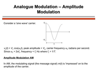
  • 1. Analogue Modulation – Amplitude Modulation v c ( t ) = V c cos (  c t ), peak amplitude = V c , carrier frequency  c radians per second. Since  c = 2  f c , frequency = f c Hz where f c = 1/ T . Consider a 'sine wave' carrier. Amplitude Modulation AM In AM, the modulating signal (the message signal) m ( t ) is 'impressed' on to the amplitude of the carrier.
  • 2. Message Signal m ( t ) In general m ( t ) will be a band of signals, for example speech or video signals. A notation or convention to show baseband signals for m ( t ) is shown below
  • 3. Message Signal m ( t ) In general m ( t ) will be band limited. Consider for example, speech via a microphone. The envelope of the spectrum would be like:
  • 6. Message Signal m ( t ) In order to make the analysis and indeed the testing of AM systems easier, it is common to make m ( t ) a test signal, i.e. a signal with a constant amplitude and frequency given by
  • 7. Schematic Diagram for Amplitude Modulation V DC is a variable voltage, which can be set between 0 Volts and + V Volts. This schematic diagram is very useful; from this all the important properties of AM and various forms of AM may be derived.
  • 8. Equations for AM From the diagram where V DC is the DC voltage that can be varied. The equation is in the form Amp cos  c t and we may 'see' that the amplitude is a function of m ( t ) and V DC . Expanding the equation we get:
  • 9. Equations for AM Now let m ( t ) = V m cos  m t, i.e. a 'test' signal, Using the trig identity we have Components: Carrier upper sideband USB lower sideband LSB Amplitude: V DC V m /2 V m /2 Frequency:  c  c +  m  c –  m f c f c + f m f c + f m This equation represents Double Amplitude Modulation – DSBAM
  • 10. Spectrum and Waveforms The following diagrams represent the spectrum of the input signals, namely ( V DC + m ( t )), with m ( t ) = V m cos  m t , and the carrier cos  c t and corresponding waveforms.
  • 11. Spectrum and Waveforms The above are input signals. The diagram below shows the spectrum and corresponding waveform of the output signal, given by
  • 13. Double Sideband AM, DSBAM The component at the output at the carrier frequency f c is shown as a broken line with amplitude V DC to show that the amplitude depends on V DC . The structure of the waveform will now be considered in a little more detail. Waveforms Consider again the diagram V DC is a variable DC offset added to the message; m ( t ) = V m cos  m t
  • 14. Double Sideband AM, DSBAM This is multiplied by a carrier, cos  c t . We effectively multiply ( V DC + m ( t )) waveform by +1, -1, +1, -1, ... The product gives the output signal
  • 16. Modulation Depth Consider again the equation , which may be written as The ratio is defined as the modulation depth , m , i.e. Modulation Depth From an oscilloscope display the modulation depth for Double Sideband AM may be determined as follows:
  • 17. Modulation Depth 2 2 E max = maximum peak-to-peak of waveform 2 E min = minimum peak-to-peak of waveform Modulation Depth This may be shown to equal as follows: = =
  • 18.
  • 19. Graphical Representation of Modulation Depth and Modulation Types.
  • 20. Graphical Representation of Modulation Depth and Modulation Types 2.
  • 21. Graphical Representation of Modulation Depth and Modulation Types 3 Note then that V DC may be set to give the modulation depth and modulation type. DSBAM V DC >> V m , m  1 DSB Dim C 0 < V DC < V m , m > 1 (1 < m <  ) DSBSC V DC = 0, m =  The spectrum for the 3 main types of amplitude modulation are summarised
  • 22. Bandwidth Requirement for DSBAM In general, the message signal m ( t ) will not be a single 'sine' wave, but a band of frequencies extending up to B Hz as shown Remember – the 'shape' is used for convenience to distinguish low frequencies from high frequencies in the baseband signal.
  • 23.
  • 24. Power Considerations in DSBAM Remembering that Normalised Average Power = ( V RMS ) 2 = we may tabulate for AM components as follows: Total Power P T = Carrier Power P c + P USB + P LSB Power Power V DC Amplitude pk LSB USB Carrier Component
  • 25. Power Considerations in DSBAM From this we may write two equivalent equations for the total power P T , in a DSBAM signal The carrier power and or i.e. Either of these forms may be useful. Since both USB and LSB contain the same information a useful ratio which shows the proportion of 'useful' power to total power is
  • 26. Power Considerations in DSBAM For DSBAM ( m  1), allowing for m ( t ) with a dynamic range, the average value of m may be assumed to be m = 0.3 Hence, on average only about 2.15% of the total power transmitted may be regarded as 'useful' power. (  95.7% of the total power is in the carrier!) Hence, Even for a maximum modulation depth of m = 1 for DSBAM the ratio i.e. only 1/6th of the total power is 'useful' power (with 2/3 of the total power in the carrier).
  • 28. Example Suppose you have a portable (for example you carry it in your ' back pack') DSBAM transmitter which needs to transmit an average power of 10 Watts in each sideband when modulation depth m = 0.3. Assume that the transmitter is powered by a 12 Volt battery. The total power will be where = 10 Watts, i.e. = 444.44 Watts Hence, total power P T = 444.44 + 10 + 10 = 464.44 Watts. Hence, battery current (assuming ideal transmitter) = Power / Volts = i.e. a large and heavy 12 Volt battery. amps! Suppose we could remove one sideband and the carrier, power transmitted would be 10 Watts, i.e. 0.833 amps from a 12 Volt battery, which is more reasonable for a portable radio transmitter.
  • 29. Single Sideband Amplitude Modulation One method to produce signal sideband (SSB) amplitude modulation is to produce DSBAM, and pass the DSBAM signal through a band pass filter, usually called a single sideband filter, which passes one of the sidebands as illustrated in the diagram below. The type of SSB may be SSBAM (with a 'large' carrier component), SSBDimC or SSBSC depending on V DC at the input. A sequence of spectral diagrams are shown on the next page.
  • 31. Single Sideband Amplitude Modulation Note that the bandwidth of the SSB signal B Hz is half of the DSB signal bandwidth. Note also that an ideal SSB filter response is shown. In practice the filter will not be ideal as illustrated. As shown, with practical filters some part of the rejected sideband (the LSB in this case) will be present in the SSB signal. A method which eases the problem is to produce SSBSC from DSBSC and then add the carrier to the SSB signal.
  • 33. Single Sideband Amplitude Modulation with m ( t ) = V m cos  m t , we may write: The SSB filter removes the LSB (say) and the output is Again, note that the output may be SSBAM, V DC large SSBDimC, V DC small SSBSC, V DC = 0 For SSBSC, output signal =
  • 34. Power in SSB From previous discussion, the total power in the DSB signal is Hence, if P c and m are known, the carrier power and power in one sideband may be determined. Alternatively, since SSB signal = then the power in SSB signal (Normalised Average Power) is Power in SSB signal = = for DSBAM.
  • 35.
  • 36. Envelope or Non-Coherent Detection This is obviously simple, low cost. But the AM input must be DSBAM with m << 1, i.e. it does not demodulate DSBDimC, DSBSC or SSBxx. An envelope detector for AM is shown below:
  • 37. Large Signal Operation For large signal inputs, (  Volts) the diode is switched i.e. forward biased  ON, reverse biased  OFF, and acts as a half wave rectifier. The 'RC' combination acts as a 'smoothing circuit' and the output is m ( t ) plus 'distortion'. If the modulation depth is > 1, the distortion below occurs
  • 38. Small Signal Operation – Square Law Detector For small AM signals (~ millivolts) demodulation depends on the diode square law characteristic. The diode characteristic is of the form i ( t ) = av + bv2 + cv3 + ... , where i.e. DSBAM signal.
  • 39. Small Signal Operation – Square Law Detector = = = 'LPF' removes components. Signal out = i.e. the output contains m ( t ) i.e.
  • 40. Synchronous or Coherent Demodulation A synchronous demodulator is shown below This is relatively more complex and more expensive. The Local Oscillator (LO) must be synchronised or coherent, i.e. at the same frequency and in phase with the carrier in the AM input signal. This additional requirement adds to the complexity and the cost. However, the AM input may be any form of AM, i.e. DSBAM, DSBDimC, DSBSC or SSBAM, SSBDimC, SSBSC. (Note – this is a 'universal' AM demodulator and the process is similar to correlation – the LPF is similar to an integrator).
  • 41. Synchronous or Coherent Demodulation If the AM input contains a small or large component at the carrier frequency, the LO may be derived from the AM input as shown below.
  • 42. Synchronous (Coherent) Local Oscillator If we assume zero path delay between the modulator and demodulator, then the ideal LO signal is cos(  c t ). Note – in general the will be a path delay, say  , and the LO would then be cos(  c ( t –  ), i.e. the LO is synchronous with the carrier implicit in the received signal. Hence for an ideal system with zero path delay Analysing this for a DSBAM input =
  • 43. Synchronous (Coherent) Local Oscillator V X = AM input x LO = We will now examine the signal spectra from 'modulator to V x' = =
  • 44. Synchronous (Coherent) Local Oscillator (continued on next page)
  • 45. Synchronous (Coherent) Local Oscillator Note – the AM input has been 'split into two' – 'half' has moved or shifted up to and half shifted down to baseband, and and and and and and
  • 46.
  • 47. 1. Double Sideband (DSB) AM Inputs The equation for DSB is diminished carrier or suppressed carrier to be set. where VDC allows full carrier (DSBAM), Hence, Vx = AM Input x LO Since
  • 48. 1. Double Sideband (DSB) AM Inputs The LPF with a cut-off frequency  f c Hz will remove the components at 2  c (i.e. components above  c ) and hence Obviously, if and we have, as previously Consider now if  is equivalent to a few Hz offset from the ideal LO. We may then say The output, if speech and processed by the human brain may be intelligible, but would include a low frequency 'buzz' at  , and the message amplitude would fluctuate. The requirement  = 0 is necessary for DSBAM.
  • 49. 1. Double Sideband (DSB) AM Inputs Consider now if  is equivalent to a few Hz offset from the ideal LO. We may then say The output, if speech and processed by the human brain may be intelligible, but would include a low frequency 'buzz' at  , and the message amplitude would fluctuate. The requirement  = 0 is necessary for DSBAM. Consider now that  = 0 but   0, i.e. the frequency is correct at  c but there is a phase offset. Now we have 'cos(  )' causes fading (i.e. amplitude reduction) of the output.
  • 50.
  • 51. 1. Double Sideband (DSB) AM Inputs If the phase offset varies with time, then the signal fades in and out. The variation of amplitude of the output, with phase offset  is illustrated below Thus the requirement for  = 0 and  = 0 is a 'strong' requirement for DSB amplitude modulation.
  • 52. 2. Single Sideband (SSB) AM Input The equation for SSB with a carrier depending on V DC is i.e. assuming Hence =
  • 53. 2. Single Sideband (SSB) AM Input The LPF removes the 2  c components and hence Note, if  = 0 and  = 0, ,i.e. has been recovered. Consider first that   0, e.g. an offset of say 50Hz. Then If m(t) is a signal at say 1kHz, the output contains a signal a 50Hz, depending on V DC and the 1kHz signal is shifted to 1000Hz - 50Hz = 950Hz.
  • 54. 2. Single Sideband (SSB) AM Input The spectrum for V out with  offset is shown Hence, the effect of the offset  is to shift the baseband output, up or down, by  . For speech, this shift is not serious (for example if we receive a 'whistle' at 1kHz and the offset is 50Hz, you hear the whistle at 950Hz (  = +ve) which is not very noticeable. Hence, small frequency offsets in SSB for speech may be tolerated. Consider now that  = 0,  = 0, then
  • 55.
  • 56.
  • 57. Phase Shift Method for SSB Generation The diagram below shows the Phase Shift Method for generating SSBSC f m and f c denote phase shifts at the message frequency (f m ) and the carrier frequency (f c ).
  • 58. Phase Shift Method for SSB Generation Solving for V out in general terms i.e. Since The actual form of the modulation at the output will depend on the phase shifts f m and f c .
  • 59. Phase Shift Method for SSB Generation Consider V out when (i.e.90 0 ) Since then When fm = 90 0 and fc = 90 0 the output is Single Sideband Suppressed Carrier – Lower Sideband. , i.e. SSBSC/LSB.
  • 60. Phase Shift Method for SSB Generation Consider V out when , and since then i.e. SSBSC/USB. When f m = 90 0 and f c = -90 0 the output is Single Sideband Suppressed Carrier – Upper Sideband. Note – for m(t) as a band of signals, the phase shift f m must be the same e.g.  /2 or 90 0 at all frequencies.
  • 61. Exercise 1) When f m = 0 and f c = 0 show that 2) When f m = 0 and f c =  show that V out = 0
  • 62. Quadrature Modulation A variation on the Phase Shift Method is shown below In this form of the method, 2 different message signals m 1 (t) and m 2 (t) are input.
  • 63. Quadrature Modulation The carrier is phase shifted by 90 0 to give The two carriers, and are in phase quadrature (orthogonal). Quadrature Modulation or Quadrature Multiplexing and as Independent Sideband ISB. The process is described as Clearly, .
  • 64. Quadrature Modulation Each 'term' in the output is a DSBSC signal occupying the same bandwidth, but phase shifted by 90 0 relative to each other
  • 65. Quadrature Modulation Demodulation will require synchronous demodulators as shown below.
  • 66. Quadrature Modulation Clearly Since Since the LPF with cut-off frequency = f c , the output Similarly, Since Again, LPF removes the '2wc components, i.e.
  • 67. Quadrature Modulation This type of modulation/multiplexing is used in radio systems, television and as a form of stereo multiplexing for AM radio.
  • 68. Vestigial Sideband Modulation Some signals, such as TV signals contain low frequencies, or even extend down to DC. When DSB modulated we have
  • 69. Vestigial Sideband Modulation It is now impossible to produce SSB, because the SSB filter would need to be ideal, as shown above. In practice the filter is as below The signal produced is called vestigial sideband, it contains the USB and a 'vestige' of the lower sideband. The BPF design is therefore less stringent. When demodulated the baseband signal is the sum of the USB and the vestige of the LSB
  • 70. Vestigial Sideband Modulation Hence the original baseband signal. VSB is used in TV systems.