Vibration monitoring of Pumps. Monitoreo de Vibraciones para Bombas
•
1 recomendación•660 vistas

Predictive Maintenance by Condition Monitoring through Vibration Monitoring of Pumps. Mantenimiento preventivo de bombas por medio de Sistemas de Monitoreo de las Vibraciones

Recomendados
Recomendados
Más contenido relacionado
La actualidad más candente
La actualidad más candente (20)
Similar a Vibration monitoring of Pumps. Monitoreo de Vibraciones para Bombas
Similar a Vibration monitoring of Pumps. Monitoreo de Vibraciones para Bombas (20)
Más de P&L International Trading
Más de P&L International Trading (20)
Último
Último (20)
Vibration monitoring of Pumps. Monitoreo de Vibraciones para Bombas
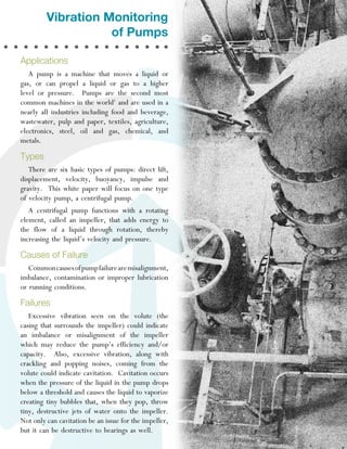
- 1. Vibration Monitoring of Pumps Applications A pump is a machine that moves a liquid or gas, or can propel a liquid or gas to a higher level or pressure. Pumps are the second most common machines in the world1 and are used in a nearly all industries including food and beverage, wastewater, pulp and paper, textiles, agriculture, electronics, steel, oil and gas, chemical, and metals. Types There are six basic types of pumps: direct lift, displacement, velocity, buoyancy, impulse and gravity. This white paper will focus on one type of velocity pump, a centrifugal pump. A centrifugal pump functions with a rotating element, called an impeller, that adds energy to the flow of a liquid through rotation, thereby increasing the liquid’s velocity and pressure. Causes of Failure Common causes of pump failure are misalignment, imbalance, contamination or improper lubrication or running conditions. Failures Excessive vibration seen on the volute (the casing that surrounds the impeller) could indicate an imbalance or misalignment of the impeller which may reduce the pump’s efficiency and/or capacity. Also, excessive vibration, along with crackling and popping noises, coming from the volute could indicate cavitation. Cavitation occurs when the pressure of the liquid in the pump drops below a threshold and causes the liquid to vaporize creating tiny bubbles that, when they pop, throw tiny, destructive jets of water onto the impeller. Not only can cavitation be an issue for the impeller, but it can be destructive to bearings as well.
- 2. bearing failure. For horizontally mounted centrifugal pumps the sensor should be installed perpendicular to the shaft on the bearing case. On a vertically mounted pump two sensors should be installed 90 degrees from each other and perpendicular to the shaft on the bearing case. For axial measurements for a vertically mounted pump, a sensor can be installed on a location near the pump casing. Analysis Figure 1: Cavitation damage on an impeller. Cavitation is not only a problem in and of itself, but is also an incation of poor pump performance. If cavitation is not caught, it can shorten the pump’s life, increase other maintenance requirements, and threaten the pump’s reliability. (Photo source: “Solving a Cavitation Problem,” http://jacpump. wordpress.com/2011/04/17/solving-a-cavitationproblem/) Vibration monitoring of the stuffing box can detect seal lubricants changing from a liquid state to a gas or solid which can lead to seal failure. This is especially a potential problem in hot water applications. What Should Be Measured Centrifugal pumps have multiple areas of interest for monitoring in a predictive maintenance program. The first area of interest for monitoring is the volute. The second area of interest is the stuffing box/seal area which is the joint that prevents fluid in the pump from coming out of the pump between the volute and pump shaft. The third area of interest is the bearing case, which can be monitored to detect Centrifugal pumps vibrate at multiples of the motor running speed and of the blade pass frequency (BPF) which is defined as the number of blades multiplied by the pump’s running speed in hertz. When a gearbox is present between the motor and pump, the BPF is the running speed times the gear ratio times the number of blades. In general, the maximum vibration levels occur at the BPF. Typical centrifugal pumps have running speeds of 1,500-1,800 RPM (4-pole motor) or 3,000-3,600 RPM (2-pole motor). Savings Efficiencies around 80 percent are possible for centrifugal pumps, but studies show that the average pump is running at an efficiency below 40 percent, and more than ten percent of pumps run below ten percent efficiency. While the reasons vary, it is clear that there is dramatic room for improvement with enhanced awareness of the pump systems. Unexpected failures can be disruptive and sometimes catastrophic. Take for example a fire that broke out at an oil refinery. The fire forced a three-day shut down of the refinery and cost $1.5 million in damages and lost production. It was later discovered that the cause of the fire was a pump that was being run inefficiently. Since the fire, the refinery has installed a monitoring system and two years after installing the system, the refineries pump system has yet to require unplanned maintenance.1 KCF Technologies 336 South Fraser Street State College, PA 16801 Phone: +1 814-867-4097 E-mail: sales@kcftech.com www.kcftech.com
- 3. Figure 2: Diagram of a centrifugal pump. Additional Things You May Want to Know The motor bearing frequencies are calculated based on the running speed and the bearing geometry. For rolling element bearings, the following formulas are used: u Pass Frequency Outer Race (BPFO) = Nb/2 x S x (1 – (Bd/Pd * cos (th)) Ball u Ball Pass Frequency Inner Race (BPFI) = Nb/2 x S x (1 + (Bd/Pd * cos (th)) u Fundamental Train Frequency (FTF) = S/2 x (1 – (Bd/Pd x cos (th)) u Ball Spin Frequency (BSF) = Pd/2Bd x S x (1 – (Bd/Pd * cos (th)) Where: u u u u u Nb = number of rolling elements S = speed (revolutions per second, in Hz) Bd = ball diameter Pd = pitch diameter th = contact angle (degrees) The following guidelines can be used as a quick reference: u u u u Ball Pass Frequency Outer Race (BPFO) = Nb x S x 0.4 Ball Pass Frequency Inner Race (BPFI) = Nb x S x 0.6 Fundamental Train Frequency (FTF) = S x 0.4 Ball Spin Frequency (BSF) = S x 1.6 KCF Technologies 336 South Fraser Street State College, PA 16801 Phone: +1 814-867-4097 E-mail: sales@kcftech.com www.kcftech.com
- 4. For example, a centrifugal pump with 8 blades operating at 1,800 RPM with 19 rolling elements in each bearing will have the following frequencies: Fundamental Train Frequency (FTF) 1X Motor Speed Ball Spin Frequency (BSF) 2X Motor Speed Ball Pass Frequency Outer Race (BPFO) Blade Pass Frequency (FPF) Ball Pass Frequency Outer Race (BPFI) 12Hz 30Hz 48Hz 60Hz 228Hz 240Hz 342Hz The vibration spectrum will display a peak at each frequency noted above. The actual frequency will be slightly lower as the speed slows under load with motor slip of a few percent. The analysis should be performed over a frequency band accommodated this range of speed variation. For variable-speed pumps, the motor speed will vary over a range of speeds based on the required pressure or flow rate, or peak efficiency. Each peak is analyzed for a trend in amplitude against pre-set warning and alarm levels. Specific information may be available from individual manufacturers or through operational specifications. The following guidelines provide a useful start for analyzing the FFT max amplitudes in each band for a pump: General (rotation and bearing locations including motor speed, FTF, BSF, BPFO, BPFI) Level Warning Alarm Shutdown Amplitude (max) 0.10 in/s 0.25 in/s 0.62 in/s Kernan, Daniel. “Pumps 101: Operation, Maintenance, and Monitoring Basics.” gouldspumps.com. ITT Corporation, n.d. Web. 22 June 2012. 1 KCF Technologies 336 South Fraser Street State College, PA 16801 Phone: +1 814-867-4097 E-mail: sales@kcftech.com www.kcftech.com