SlideShare una empresa de Scribd logo
1 de 10
Descargar para leer sin conexión
ELECTRICAL CIRCUITS


Electrical Circuits
A complete path, or circuit, is needed before           current path if too much current flows. Too much
voltage can cause a current flow through                current is called an overload, which could
resistances to perform work.                            damage conductors and working devices.
                                                        A list of five things to look for in any circuit:
There are several types of circuits, but all require
the same basic components. A power source                       1. Source of Voltage
(battery or alternator) produces voltage, or                    2. Protection Device
electrical potential. Conductors (wires, printed
circuit boards) provide a path for current flow.                3. Load
Working devices, or loads (lamps, motors),                      4. Control
change the electrical energy into another form of
energy to perform work. Control devices                         5. Ground
(switches, relays) turn the current flow on and
off. And, protection devices (fuses, circuit            We will be identifying these items when we look at
breakers) interrupt the                                 Automotive Circuits a little later in this book.


                                                   Page 1   © Toyota Motor Sales, U.S.A., Inc. All Rights Reserved.
ELECTRICAL CIRCUITS


Types Of Circuits
There are three basic types of circuits: series,
parallel, and series-parallel. The type of circuit
is determined by how the power source,
conductors, loads, and control or protective
devices are connected.

SERIES CIRCUIT

A series circuit is the simplest circuit. The
conductors, control and protection devices, loads,
and power source are connected with only one
path for current. The resistance of each device
can be different. The same amount of current will
flow through each. The voltage across each will
be different. If the path is broken, no current
flows.

PARALLEL CIRCUIT

A parallel circuit has more than one path for
current flow. The same voltage is applied across
each branch. If the load resistance in each branch
is the same, the current in each branch will be the
same. If the load resistance in each branch is
different, the current in each branch will be
different. If one branch is broken, current will
continue flowing to the other branches.

SERIES-PARALLEL CIRCUIT

A series-parallel circuit has some components in
series and others in parallel. The power source
and control or protection devices are usually in
series; the loads are usually in parallel. The same
current flows in the series portion, different
currents in the parallel portion. The same voltage is
applied to parallel devices, different voltages to
series devices. If the series portion is broken,
current stops flowing in the entire circuit. If a
parallel branch is broken, current continues
flowing in the series portion and the remaining
branches.


                                                   Page 2   © Toyota Motor Sales, U.S.A., Inc. All Rights Reserved.
ELECTRICAL CIRCUITS


SERIES CIRCUITS

In a series circuit, current has only one path. All        voltage on the other side of the load. The drop or
the circuit components are connected so that the           loss in voltage is proportional to the amount of
same amount of current flows through each. The             resistance. The higher the resistance, the higher
circuit must have continuity. If a wire is                 the voltage drop.
disconnected or broken, current stops flowing. If
one load is open, none of the loads will work.             When troubleshooting, then, you can see that more
                                                           resistance will reduce current and less resistance
Use of Ohm's Law                                           will increase current. Low voltage would also
                                                           reduce current and high voltage would increase
Applying Ohm's Law to series circuits is easy.             current. Reduced current will affect component
Simply add up the load resistances and divide the          operation (dim lamps, slow motors). But, increased
total resistance into the available voltage to find the    current will also affect component operation (early
current. The voltage drops across the load                 failure, blown fuses). And, of course, no current at
resistances are then found by multiplying the              all would mean that the entire circuit would not
current by each load resistance. For calculation           operate. There are electrical faults that can cause
examples, see page 6 in the Ohms law section.              such problems and knowing the relationship
Voltage drop is the difference in voltage                  between voltage, current, and resistance will help
(pressure) on one side of a load compared to the           to identify the cause of the problem.


                                                      Page 3   © Toyota Motor Sales, U.S.A., Inc. All Rights Reserved.
ELECTRICAL CIRCUITS


PARALLEL CIRCUITS

In a parallel circuit, current can flow through more      the smallest load resistance. This makes sense
than one path from and to the power source. The           because current can flow through more than one
circuit loads are connected in parallel legs, or          path. Also, remember that the voltage drop across
branches, across a power source. The points               each branch will be the same because the source
where the current paths split and rejoin are called       voltage is applied to each branch. For examples of
junctions. The separate current paths are called          how to calculate parallel resistance, see page 6.
branch circuits or shunt circuits. Each branch
operates independent of the others. If one load           When troubleshooting a parallel circuit, the loss of
opens, the others continue operating.                     one or more legs will reduce current because the
                                                          number of paths is reduced. The addition of one or
Use of Ohm's Law                                          more legs will increase current because the
                                                          number of paths is increased. Current can also be
Applying Ohm's Law to parallel circuits is a bit          reduced by low source voltage or by resistance in
more difficult than with series circuits. The reason      the path before the branches. And, current can be
is that the branch resistances must be combined to        increased by high source voltage or by one or
find an equivalent resistance. Just remember that         more legs being bypassed. High resistance in one
the total resistance in a parallel circuit is less than   leg would affect component operation only in that
                                                          leg.


                                                    Page 4    © Toyota Motor Sales, U.S.A., Inc. All Rights Reserved.
ELECTRICAL CIRCUITS


SERIES-PARALLEL CIRCUITS

In a series-parallel circuit, current flows through         The total resistance is then divided into the source
the series portion of the circuit and then splits to        voltage to find current. Voltage drop across series
flow through the parallel branches of the circuit.          loads is current times resistance. Current in
Some components are wired in series, others in              branches is voltage divided by resistance. For
parallel. Most automotive circuits are series-              calculation examples, see page 6.
parallel, and the same relationship between
voltage, current, and resistance exists.                    When troubleshooting a series-parallel circuit,
                                                            problems in the series portion can shut down the
Use of Ohm's Law                                            entire circuit while a problem in one leg of the
                                                            parallel portion may or may not affect the entire
Applying Ohm's Law to series-parallel circuits is a         circuit, depending on the problem. Very high
matter of simply combining the rules seen for               resistance in one leg would reduce total circuit
series circuits and parallel circuits. First, calculate     current, but increase current in other legs. Very
the equivalent resistance of the parallel loads and         low resistance in one leg would increase total
add it to the resistances of the loads in series.           circuit current and possibly have the effect of
                                                            bypassing other legs.


                                                       Page 5   © Toyota Motor Sales, U.S.A., Inc. All Rights Reserved.
ELECTRICAL CIRCUITS


Ohm's Law                                                sample circuits. Current found by dividing voltage
                                                         by resistance. This can be very helpful when
Fast, accurate electrical troubleshooting is easy        diagnosing electrical problems:
when you know how voltage, current, and
resistance are related. Ohm's Law explains the           • When the resistance stays the same ... current
relationship:                                            goes up as voltage goes up, and current goes
                                                         down as voltage goes down. A discharged battery
• Current (amps) equals voltage (volts) divided by       has low voltage which reduces current. Some
  resistance (ohms) ... I = E ÷ R.                       devices may fail to operate (slow motor speed). An
                                                         unregulated alternator may produce too much
• Voltage (volts) equals current (amps) times            voltage which increases current. Some devices
  resistance (ohms) ... E = I X R.                       may fail early (burned-out lamps).

• Resistance (ohms) equals voltage (volts) divided       • When the voltage stays the same ... current goes
  by current (amps) ... R ÷ E = 1.                       up as resistance goes down, and current goes
                                                         down as resistance goes up. Bypassed devices
USING OHM'S LAW                                          reduce resistance, causing high current. Loose
                                                         connections increase resistance, causing low
                                                         current.
The effects of different voltages and different
resistances on current flow can be seen in the


                                                    Page 6   © Toyota Motor Sales, U.S.A., Inc. All Rights Reserved.
ELECTRICAL CIRCUITS


SAMPLE CALCULATIONS                                      Ohm's law includes these two ideas:

Here are some basic formulas you will find helpful       1. In a circuit, if resistance is constant, current
in solving more complex electrical problems. They        varies directly with voltage.
provide the knowledge required for confidence
and thorough understanding of basic electricity.         Now what this means is that if you take a
                                                         component with a fixed resistance, say a light bulb,
The following abbreviations are used in the              and double the voltage you double the current
formulas:                                                flowing through it. Anyone who has hooked a six-
                                                         volt bulb to a twelve-volt circuit has experienced
        E = VOLTS                                        this. But it wasn't "too many volts" that burned out
        I = AMPS                                         the bulb, it was too much current. More about that
        R = OHMS                                         later.
        P = WATTS
                                                         2. In a circuit, if voltage is constant, current varies
• Ohm's Law                                              inversely with resistance.

Scientifically stated, it says: "The intensity Of the    This second idea states that when resistance goes
current in amperes in any electrical circuit is equal    up, current goes down. That's why corroded
to the difference in potential in volts across the       connectors cause very dim lights - not enough
circuit divided by the resistance in ohms of the         current.
circuit." Simply put it means that current is equal to
volts divided by ohms, or expressed as a formula,        • Watts
the law becomes:
                                                         A watt is an electrical measurement of power or
        I=E/R                                            work. It directly relates to horsepower. In fact, in
                                                         the Sl metric standards that most of the world
or it can be written:                                    uses, engine power is given in watts or kilowatts.

        E=IXR                                            Electrical power is easily calculated by the formula:

This is important because if you know any two of         P=EXI
the quantities, the third may be found by applying
the equation.                                            For instance, a halogen high-beam headlight is
                                                         rated or 5 amps of current. Figuring 12 volts in the
                                                         system, we could write:

                                                                 P=EXI
                                                                 P = 12 X 5
                                                                 P = 60 watts


                                                    Page 7   © Toyota Motor Sales, U.S.A., Inc. All Rights Reserved.
ELECTRICAL CIRCUITS


RESISTANCE                                                   That becomes:

The effect of individual resistors on the total
resistance of a circuit depends on whether the
circuit is series or parallel.                               Which becomes:

Series Circuits

In a series circuit, the total resistance is equal to
the sum of the individual resistors:                         So there is a little more than one-half ohm
                                                             resistance in the circuit. You can see that the more
SERIES:                                                      resistors in parallel, the less the resistance.

total R = R1 + R2 + R3 +                                     In fact, the total resistance is always less than the
                                                             smallest resistor. This is why a fuse will blow if
That is the basis of the concept of voltage drop.            you add too many circuits to the fuse. There are so
For example, if you had a circuit with three loads in        many paths for the current to follow that the total
series (a bulb, resistor, and corroded ground) you           resistance of the circuit is very low. That means
would add the three together to get total                    the current is very high - so high that the fuse can
resistance. And, of course, the voltage would                no longer handle the load.
drop across each load according to its value.
                                                             B. For two resistors:
Parallel Circuits

Parallel circuits are a different story. In a parallel
circuit, there are three ways to find total
                                                             For a 3 ohm and a 5 ohm resistor that would be:
resistance. Method A works in all cases. Method B
works only if there are two branches, equal or
not. Method C works only if the branches are of
equal resistance.
A. The total resistance is equal to one over the
                                                             C. For several identical resistors, divide the value
   sum of the reciprocals of the individual
                                                             of one resistor by the number of resistors, or:
   resistors. That sounds confusing, but looking at
   the formula will make it clearer:

PARALLEL:
                                                             Where R1 is the value of one resistor and n is the
                                                             number of resistors. So if you had three 4 ohm
                                                             resistors in parallel it would be:
n example will make it even clearer. Suppose there
is a circuit with three resistors in parallel: 4 ohms,
2 ohms, and 1 ohm. The formula would look like
this:


                                                        Page 8   © Toyota Motor Sales, U.S.A., Inc. All Rights Reserved.
ELECTRICAL CIRCUITS


Page 9   © Toyota Motor Sales, U.S.A., Inc. All Rights Reserved.
ELECTRICAL CIRCUITS


ASSIGNMENT                             NAME:


1.   Draw and label the parts of a Series Circuit and a Parallel Circuit.

2.   Explain the characteristics of “Voltage” and how it differs between a Series
     Circuit and a Parallel Circuit.

3.   Explain the characteristics of “Current” and how it differs between a Series
     Circuit and a Parallel Circuit.

4.   Explain the characteristics of “Resistance” and how it differs between a Series
     Circuit and a Parallel Circuit.

Más contenido relacionado

La actualidad más candente

Ib review 5 - circuits
Ib review   5 - circuitsIb review   5 - circuits
Ib review 5 - circuitsjsawyer3434
 
Basic Electrical Equipment module-1
Basic Electrical Equipment module-1Basic Electrical Equipment module-1
Basic Electrical Equipment module-1Aijaz Ali Mooro
 
ohm's law and circuits
ohm's law and  circuitsohm's law and  circuits
ohm's law and circuitsimran khan
 
All about motor
All about motorAll about motor
All about motoranil0943
 
Single phase transformers
Single phase transformersSingle phase transformers
Single phase transformersEkeeda
 
Chapter 33
Chapter 33Chapter 33
Chapter 33mcfalltj
 
Three Point Starter: Diagram and Working Principle
Three Point Starter: Diagram and Working PrincipleThree Point Starter: Diagram and Working Principle
Three Point Starter: Diagram and Working PrincipleDr.Raja R
 
Current electricity
Current electricityCurrent electricity
Current electricityMussaOmary3
 
Electrical interview-questions-answers
Electrical interview-questions-answersElectrical interview-questions-answers
Electrical interview-questions-answersRaghavendra Kiran
 
ohm's law
ohm's lawohm's law
ohm's law2461998
 
Electromagnetic Induction
Electromagnetic InductionElectromagnetic Induction
Electromagnetic Inductionlboehmer
 

La actualidad más candente (20)

Ppt 2
Ppt 2Ppt 2
Ppt 2
 
Ib review 5 - circuits
Ib review   5 - circuitsIb review   5 - circuits
Ib review 5 - circuits
 
Basic Electrical Equipment module-1
Basic Electrical Equipment module-1Basic Electrical Equipment module-1
Basic Electrical Equipment module-1
 
ohm's law and circuits
ohm's law and  circuitsohm's law and  circuits
ohm's law and circuits
 
All about motor
All about motorAll about motor
All about motor
 
Single phase transformers
Single phase transformersSingle phase transformers
Single phase transformers
 
Chapter 33
Chapter 33Chapter 33
Chapter 33
 
Circuits
CircuitsCircuits
Circuits
 
Digital electronics
Digital electronicsDigital electronics
Digital electronics
 
Contactor
ContactorContactor
Contactor
 
Voltage and current basics
Voltage and current   basicsVoltage and current   basics
Voltage and current basics
 
Three Point Starter: Diagram and Working Principle
Three Point Starter: Diagram and Working PrincipleThree Point Starter: Diagram and Working Principle
Three Point Starter: Diagram and Working Principle
 
Current electricity
Current electricityCurrent electricity
Current electricity
 
Chapter 14 - Ohm's Law
Chapter 14 - Ohm's LawChapter 14 - Ohm's Law
Chapter 14 - Ohm's Law
 
Transformer by Hemant
Transformer by HemantTransformer by Hemant
Transformer by Hemant
 
Electrical interview-questions-answers
Electrical interview-questions-answersElectrical interview-questions-answers
Electrical interview-questions-answers
 
Alternator
AlternatorAlternator
Alternator
 
Basic Electrical
Basic Electrical Basic Electrical
Basic Electrical
 
ohm's law
ohm's lawohm's law
ohm's law
 
Electromagnetic Induction
Electromagnetic InductionElectromagnetic Induction
Electromagnetic Induction
 

Destacado

Factors considered for High Voltage Cable Joint design
Factors considered for High Voltage Cable Joint design Factors considered for High Voltage Cable Joint design
Factors considered for High Voltage Cable Joint design Shahab Khan
 
Power Cables, Electrical Power & Industrial Cable, Electrical Wire, PVC Wire ...
Power Cables, Electrical Power & Industrial Cable, Electrical Wire, PVC Wire ...Power Cables, Electrical Power & Industrial Cable, Electrical Wire, PVC Wire ...
Power Cables, Electrical Power & Industrial Cable, Electrical Wire, PVC Wire ...Ajjay Kumar Gupta
 
Transformer design and protection
Transformer design and protectionTransformer design and protection
Transformer design and protectionashwin fcc
 
Electronics for-you-projects-and-ideas-2000
Electronics for-you-projects-and-ideas-2000Electronics for-you-projects-and-ideas-2000
Electronics for-you-projects-and-ideas-2000nonshahid
 
70 interesting circuits
70 interesting circuits70 interesting circuits
70 interesting circuitsvietem0610
 
Make electronics
Make   electronicsMake   electronics
Make electronicsPaulGoggin
 
Electrical power transmission system
Electrical power transmission systemElectrical power transmission system
Electrical power transmission systemAbdul Wahab Malik
 
Power transformer protection
Power transformer protectionPower transformer protection
Power transformer protectionmichaeljmack
 
Protection of power transformer
Protection of power transformerProtection of power transformer
Protection of power transformerRitesh Verma
 
Relay and switchgear protection
Relay and switchgear protectionRelay and switchgear protection
Relay and switchgear protectionBinit Das
 
Protective relay
Protective relay Protective relay
Protective relay Uday Wankar
 
Computer systems servicing cbc
Computer systems servicing cbcComputer systems servicing cbc
Computer systems servicing cbcHanzel Metrio
 
POWER SYSTEM PROTECTION
POWER SYSTEM PROTECTION POWER SYSTEM PROTECTION
POWER SYSTEM PROTECTION moiz89
 

Destacado (15)

Factors considered for High Voltage Cable Joint design
Factors considered for High Voltage Cable Joint design Factors considered for High Voltage Cable Joint design
Factors considered for High Voltage Cable Joint design
 
Single line diagram
Single line diagramSingle line diagram
Single line diagram
 
Transformer protection
Transformer protectionTransformer protection
Transformer protection
 
Power Cables, Electrical Power & Industrial Cable, Electrical Wire, PVC Wire ...
Power Cables, Electrical Power & Industrial Cable, Electrical Wire, PVC Wire ...Power Cables, Electrical Power & Industrial Cable, Electrical Wire, PVC Wire ...
Power Cables, Electrical Power & Industrial Cable, Electrical Wire, PVC Wire ...
 
Transformer design and protection
Transformer design and protectionTransformer design and protection
Transformer design and protection
 
Electronics for-you-projects-and-ideas-2000
Electronics for-you-projects-and-ideas-2000Electronics for-you-projects-and-ideas-2000
Electronics for-you-projects-and-ideas-2000
 
70 interesting circuits
70 interesting circuits70 interesting circuits
70 interesting circuits
 
Make electronics
Make   electronicsMake   electronics
Make electronics
 
Electrical power transmission system
Electrical power transmission systemElectrical power transmission system
Electrical power transmission system
 
Power transformer protection
Power transformer protectionPower transformer protection
Power transformer protection
 
Protection of power transformer
Protection of power transformerProtection of power transformer
Protection of power transformer
 
Relay and switchgear protection
Relay and switchgear protectionRelay and switchgear protection
Relay and switchgear protection
 
Protective relay
Protective relay Protective relay
Protective relay
 
Computer systems servicing cbc
Computer systems servicing cbcComputer systems servicing cbc
Computer systems servicing cbc
 
POWER SYSTEM PROTECTION
POWER SYSTEM PROTECTION POWER SYSTEM PROTECTION
POWER SYSTEM PROTECTION
 

Similar a E lectronics

Slide Presentation-Electrical Circuits.pptx
Slide Presentation-Electrical Circuits.pptxSlide Presentation-Electrical Circuits.pptx
Slide Presentation-Electrical Circuits.pptxJocelBaquilar
 
Lecture24 basiccircuits
Lecture24 basiccircuitsLecture24 basiccircuits
Lecture24 basiccircuitsAlex Klein
 
Physics parallel lesson
Physics parallel lessonPhysics parallel lesson
Physics parallel lessonssuserba742a1
 
Electricity.pptx............................
Electricity.pptx............................Electricity.pptx............................
Electricity.pptx............................taliahspence123
 
Electric Circuits
Electric CircuitsElectric Circuits
Electric Circuitsitutor
 
ABE Review Class July 2022.pptx
ABE Review Class July 2022.pptxABE Review Class July 2022.pptx
ABE Review Class July 2022.pptxmechanics020377
 
Electricity Module (uploaded by Giserey)
Electricity Module (uploaded by Giserey)Electricity Module (uploaded by Giserey)
Electricity Module (uploaded by Giserey)Giserey Ocampo
 
Fairylights...Principles and Definition of Ohms Law
Fairylights...Principles and Definition of Ohms LawFairylights...Principles and Definition of Ohms Law
Fairylights...Principles and Definition of Ohms LawMuhammad Hammad Lateef
 
Introduction to electronics second session
Introduction to electronics   second sessionIntroduction to electronics   second session
Introduction to electronics second sessionKareem Elzftawy
 
M4 - Electricity.pptx
M4 - Electricity.pptxM4 - Electricity.pptx
M4 - Electricity.pptxdevie1318
 
1.pptx4168484105164649489481510120165165161
1.pptx41684841051646494894815101201651651611.pptx4168484105164649489481510120165165161
1.pptx4168484105164649489481510120165165161vikknaguem
 
AS Level Physics- Electric circuits
AS Level Physics- Electric circuitsAS Level Physics- Electric circuits
AS Level Physics- Electric circuitsEbin Robinson
 
Series circuit
Series circuit Series circuit
Series circuit rinnen_04
 
ELECTRICAL WIRING DIAGRAM.pptx
ELECTRICAL WIRING DIAGRAM.pptxELECTRICAL WIRING DIAGRAM.pptx
ELECTRICAL WIRING DIAGRAM.pptxmarcobuela
 
Circuits ppt unit 1 s2
Circuits ppt unit 1 s2Circuits ppt unit 1 s2
Circuits ppt unit 1 s2Shevon Hall
 
OHMS LAW (1).pptx
OHMS LAW (1).pptxOHMS LAW (1).pptx
OHMS LAW (1).pptxArthi579360
 

Similar a E lectronics (20)

Slide Presentation-Electrical Circuits.pptx
Slide Presentation-Electrical Circuits.pptxSlide Presentation-Electrical Circuits.pptx
Slide Presentation-Electrical Circuits.pptx
 
Parallel Circuits
Parallel CircuitsParallel Circuits
Parallel Circuits
 
Lecture24 basiccircuits
Lecture24 basiccircuitsLecture24 basiccircuits
Lecture24 basiccircuits
 
Physics parallel lesson
Physics parallel lessonPhysics parallel lesson
Physics parallel lesson
 
Electricity.pptx............................
Electricity.pptx............................Electricity.pptx............................
Electricity.pptx............................
 
Electric Circuits
Electric CircuitsElectric Circuits
Electric Circuits
 
ABE Review Class July 2022.pptx
ABE Review Class July 2022.pptxABE Review Class July 2022.pptx
ABE Review Class July 2022.pptx
 
Electricity Module (uploaded by Giserey)
Electricity Module (uploaded by Giserey)Electricity Module (uploaded by Giserey)
Electricity Module (uploaded by Giserey)
 
Fairylights...Principles and Definition of Ohms Law
Fairylights...Principles and Definition of Ohms LawFairylights...Principles and Definition of Ohms Law
Fairylights...Principles and Definition of Ohms Law
 
Introduction to electronics second session
Introduction to electronics   second sessionIntroduction to electronics   second session
Introduction to electronics second session
 
M4 - Electricity.pptx
M4 - Electricity.pptxM4 - Electricity.pptx
M4 - Electricity.pptx
 
1.pptx4168484105164649489481510120165165161
1.pptx41684841051646494894815101201651651611.pptx4168484105164649489481510120165165161
1.pptx4168484105164649489481510120165165161
 
AS Level Physics- Electric circuits
AS Level Physics- Electric circuitsAS Level Physics- Electric circuits
AS Level Physics- Electric circuits
 
Series circuit
Series circuit Series circuit
Series circuit
 
Electrical basics
Electrical basicsElectrical basics
Electrical basics
 
ELECTRICAL WIRING DIAGRAM.pptx
ELECTRICAL WIRING DIAGRAM.pptxELECTRICAL WIRING DIAGRAM.pptx
ELECTRICAL WIRING DIAGRAM.pptx
 
MODULE 1.ppt
MODULE 1.pptMODULE 1.ppt
MODULE 1.ppt
 
Circuits ppt unit 1 s2
Circuits ppt unit 1 s2Circuits ppt unit 1 s2
Circuits ppt unit 1 s2
 
OHMS LAW (1).pptx
OHMS LAW (1).pptxOHMS LAW (1).pptx
OHMS LAW (1).pptx
 
OHMS LAW.pptx
OHMS LAW.pptxOHMS LAW.pptx
OHMS LAW.pptx
 

Más de sandeep patil

Make useof.com -_how_the_internet_works
Make useof.com -_how_the_internet_worksMake useof.com -_how_the_internet_works
Make useof.com -_how_the_internet_workssandeep patil
 
Fundamentals of digital electronics
 Fundamentals of digital electronics Fundamentals of digital electronics
Fundamentals of digital electronicssandeep patil
 
Electronics en engineering-basic-vocational-knowledge
Electronics en engineering-basic-vocational-knowledgeElectronics en engineering-basic-vocational-knowledge
Electronics en engineering-basic-vocational-knowledgesandeep patil
 
01255490crosstalk noise
01255490crosstalk noise01255490crosstalk noise
01255490crosstalk noisesandeep patil
 
3 minutes-to-god-shooting-cows
3 minutes-to-god-shooting-cows3 minutes-to-god-shooting-cows
3 minutes-to-god-shooting-cowssandeep patil
 
Ctp cdnlive2005 1329mohindru.pres
Ctp cdnlive2005 1329mohindru.presCtp cdnlive2005 1329mohindru.pres
Ctp cdnlive2005 1329mohindru.pressandeep patil
 
01255490crosstalk noise
01255490crosstalk noise01255490crosstalk noise
01255490crosstalk noisesandeep patil
 
3 minutes-to-god-shooting-cows
3 minutes-to-god-shooting-cows3 minutes-to-god-shooting-cows
3 minutes-to-god-shooting-cowssandeep patil
 

Más de sandeep patil (13)

Make useof.com -_how_the_internet_works
Make useof.com -_how_the_internet_worksMake useof.com -_how_the_internet_works
Make useof.com -_how_the_internet_works
 
Fundamentals of digital electronics
 Fundamentals of digital electronics Fundamentals of digital electronics
Fundamentals of digital electronics
 
Electronics en engineering-basic-vocational-knowledge
Electronics en engineering-basic-vocational-knowledgeElectronics en engineering-basic-vocational-knowledge
Electronics en engineering-basic-vocational-knowledge
 
Electronics 01
Electronics 01Electronics 01
Electronics 01
 
3 d ic's
3 d ic's3 d ic's
3 d ic's
 
Infinity plus one
Infinity plus oneInfinity plus one
Infinity plus one
 
Buffer sizing
Buffer sizingBuffer sizing
Buffer sizing
 
Chip xtalk ebook_
Chip xtalk ebook_Chip xtalk ebook_
Chip xtalk ebook_
 
01255490crosstalk noise
01255490crosstalk noise01255490crosstalk noise
01255490crosstalk noise
 
3 minutes-to-god-shooting-cows
3 minutes-to-god-shooting-cows3 minutes-to-god-shooting-cows
3 minutes-to-god-shooting-cows
 
Ctp cdnlive2005 1329mohindru.pres
Ctp cdnlive2005 1329mohindru.presCtp cdnlive2005 1329mohindru.pres
Ctp cdnlive2005 1329mohindru.pres
 
01255490crosstalk noise
01255490crosstalk noise01255490crosstalk noise
01255490crosstalk noise
 
3 minutes-to-god-shooting-cows
3 minutes-to-god-shooting-cows3 minutes-to-god-shooting-cows
3 minutes-to-god-shooting-cows
 

Último

Digital Identity is Under Attack: FIDO Paris Seminar.pptx
Digital Identity is Under Attack: FIDO Paris Seminar.pptxDigital Identity is Under Attack: FIDO Paris Seminar.pptx
Digital Identity is Under Attack: FIDO Paris Seminar.pptxLoriGlavin3
 
Developer Data Modeling Mistakes: From Postgres to NoSQL
Developer Data Modeling Mistakes: From Postgres to NoSQLDeveloper Data Modeling Mistakes: From Postgres to NoSQL
Developer Data Modeling Mistakes: From Postgres to NoSQLScyllaDB
 
Passkey Providers and Enabling Portability: FIDO Paris Seminar.pptx
Passkey Providers and Enabling Portability: FIDO Paris Seminar.pptxPasskey Providers and Enabling Portability: FIDO Paris Seminar.pptx
Passkey Providers and Enabling Portability: FIDO Paris Seminar.pptxLoriGlavin3
 
Dev Dives: Streamline document processing with UiPath Studio Web
Dev Dives: Streamline document processing with UiPath Studio WebDev Dives: Streamline document processing with UiPath Studio Web
Dev Dives: Streamline document processing with UiPath Studio WebUiPathCommunity
 
"ML in Production",Oleksandr Bagan
"ML in Production",Oleksandr Bagan"ML in Production",Oleksandr Bagan
"ML in Production",Oleksandr BaganFwdays
 
The Fit for Passkeys for Employee and Consumer Sign-ins: FIDO Paris Seminar.pptx
The Fit for Passkeys for Employee and Consumer Sign-ins: FIDO Paris Seminar.pptxThe Fit for Passkeys for Employee and Consumer Sign-ins: FIDO Paris Seminar.pptx
The Fit for Passkeys for Employee and Consumer Sign-ins: FIDO Paris Seminar.pptxLoriGlavin3
 
TrustArc Webinar - How to Build Consumer Trust Through Data Privacy
TrustArc Webinar - How to Build Consumer Trust Through Data PrivacyTrustArc Webinar - How to Build Consumer Trust Through Data Privacy
TrustArc Webinar - How to Build Consumer Trust Through Data PrivacyTrustArc
 
SAP Build Work Zone - Overview L2-L3.pptx
SAP Build Work Zone - Overview L2-L3.pptxSAP Build Work Zone - Overview L2-L3.pptx
SAP Build Work Zone - Overview L2-L3.pptxNavinnSomaal
 
unit 4 immunoblotting technique complete.pptx
unit 4 immunoblotting technique complete.pptxunit 4 immunoblotting technique complete.pptx
unit 4 immunoblotting technique complete.pptxBkGupta21
 
What is DBT - The Ultimate Data Build Tool.pdf
What is DBT - The Ultimate Data Build Tool.pdfWhat is DBT - The Ultimate Data Build Tool.pdf
What is DBT - The Ultimate Data Build Tool.pdfMounikaPolabathina
 
Commit 2024 - Secret Management made easy
Commit 2024 - Secret Management made easyCommit 2024 - Secret Management made easy
Commit 2024 - Secret Management made easyAlfredo García Lavilla
 
Unleash Your Potential - Namagunga Girls Coding Club
Unleash Your Potential - Namagunga Girls Coding ClubUnleash Your Potential - Namagunga Girls Coding Club
Unleash Your Potential - Namagunga Girls Coding ClubKalema Edgar
 
Connect Wave/ connectwave Pitch Deck Presentation
Connect Wave/ connectwave Pitch Deck PresentationConnect Wave/ connectwave Pitch Deck Presentation
Connect Wave/ connectwave Pitch Deck PresentationSlibray Presentation
 
Take control of your SAP testing with UiPath Test Suite
Take control of your SAP testing with UiPath Test SuiteTake control of your SAP testing with UiPath Test Suite
Take control of your SAP testing with UiPath Test SuiteDianaGray10
 
DSPy a system for AI to Write Prompts and Do Fine Tuning
DSPy a system for AI to Write Prompts and Do Fine TuningDSPy a system for AI to Write Prompts and Do Fine Tuning
DSPy a system for AI to Write Prompts and Do Fine TuningLars Bell
 
Transcript: New from BookNet Canada for 2024: BNC CataList - Tech Forum 2024
Transcript: New from BookNet Canada for 2024: BNC CataList - Tech Forum 2024Transcript: New from BookNet Canada for 2024: BNC CataList - Tech Forum 2024
Transcript: New from BookNet Canada for 2024: BNC CataList - Tech Forum 2024BookNet Canada
 
Advanced Computer Architecture – An Introduction
Advanced Computer Architecture – An IntroductionAdvanced Computer Architecture – An Introduction
Advanced Computer Architecture – An IntroductionDilum Bandara
 
SIP trunking in Janus @ Kamailio World 2024
SIP trunking in Janus @ Kamailio World 2024SIP trunking in Janus @ Kamailio World 2024
SIP trunking in Janus @ Kamailio World 2024Lorenzo Miniero
 
Use of FIDO in the Payments and Identity Landscape: FIDO Paris Seminar.pptx
Use of FIDO in the Payments and Identity Landscape: FIDO Paris Seminar.pptxUse of FIDO in the Payments and Identity Landscape: FIDO Paris Seminar.pptx
Use of FIDO in the Payments and Identity Landscape: FIDO Paris Seminar.pptxLoriGlavin3
 
SALESFORCE EDUCATION CLOUD | FEXLE SERVICES
SALESFORCE EDUCATION CLOUD | FEXLE SERVICESSALESFORCE EDUCATION CLOUD | FEXLE SERVICES
SALESFORCE EDUCATION CLOUD | FEXLE SERVICESmohitsingh558521
 

Último (20)

Digital Identity is Under Attack: FIDO Paris Seminar.pptx
Digital Identity is Under Attack: FIDO Paris Seminar.pptxDigital Identity is Under Attack: FIDO Paris Seminar.pptx
Digital Identity is Under Attack: FIDO Paris Seminar.pptx
 
Developer Data Modeling Mistakes: From Postgres to NoSQL
Developer Data Modeling Mistakes: From Postgres to NoSQLDeveloper Data Modeling Mistakes: From Postgres to NoSQL
Developer Data Modeling Mistakes: From Postgres to NoSQL
 
Passkey Providers and Enabling Portability: FIDO Paris Seminar.pptx
Passkey Providers and Enabling Portability: FIDO Paris Seminar.pptxPasskey Providers and Enabling Portability: FIDO Paris Seminar.pptx
Passkey Providers and Enabling Portability: FIDO Paris Seminar.pptx
 
Dev Dives: Streamline document processing with UiPath Studio Web
Dev Dives: Streamline document processing with UiPath Studio WebDev Dives: Streamline document processing with UiPath Studio Web
Dev Dives: Streamline document processing with UiPath Studio Web
 
"ML in Production",Oleksandr Bagan
"ML in Production",Oleksandr Bagan"ML in Production",Oleksandr Bagan
"ML in Production",Oleksandr Bagan
 
The Fit for Passkeys for Employee and Consumer Sign-ins: FIDO Paris Seminar.pptx
The Fit for Passkeys for Employee and Consumer Sign-ins: FIDO Paris Seminar.pptxThe Fit for Passkeys for Employee and Consumer Sign-ins: FIDO Paris Seminar.pptx
The Fit for Passkeys for Employee and Consumer Sign-ins: FIDO Paris Seminar.pptx
 
TrustArc Webinar - How to Build Consumer Trust Through Data Privacy
TrustArc Webinar - How to Build Consumer Trust Through Data PrivacyTrustArc Webinar - How to Build Consumer Trust Through Data Privacy
TrustArc Webinar - How to Build Consumer Trust Through Data Privacy
 
SAP Build Work Zone - Overview L2-L3.pptx
SAP Build Work Zone - Overview L2-L3.pptxSAP Build Work Zone - Overview L2-L3.pptx
SAP Build Work Zone - Overview L2-L3.pptx
 
unit 4 immunoblotting technique complete.pptx
unit 4 immunoblotting technique complete.pptxunit 4 immunoblotting technique complete.pptx
unit 4 immunoblotting technique complete.pptx
 
What is DBT - The Ultimate Data Build Tool.pdf
What is DBT - The Ultimate Data Build Tool.pdfWhat is DBT - The Ultimate Data Build Tool.pdf
What is DBT - The Ultimate Data Build Tool.pdf
 
Commit 2024 - Secret Management made easy
Commit 2024 - Secret Management made easyCommit 2024 - Secret Management made easy
Commit 2024 - Secret Management made easy
 
Unleash Your Potential - Namagunga Girls Coding Club
Unleash Your Potential - Namagunga Girls Coding ClubUnleash Your Potential - Namagunga Girls Coding Club
Unleash Your Potential - Namagunga Girls Coding Club
 
Connect Wave/ connectwave Pitch Deck Presentation
Connect Wave/ connectwave Pitch Deck PresentationConnect Wave/ connectwave Pitch Deck Presentation
Connect Wave/ connectwave Pitch Deck Presentation
 
Take control of your SAP testing with UiPath Test Suite
Take control of your SAP testing with UiPath Test SuiteTake control of your SAP testing with UiPath Test Suite
Take control of your SAP testing with UiPath Test Suite
 
DSPy a system for AI to Write Prompts and Do Fine Tuning
DSPy a system for AI to Write Prompts and Do Fine TuningDSPy a system for AI to Write Prompts and Do Fine Tuning
DSPy a system for AI to Write Prompts and Do Fine Tuning
 
Transcript: New from BookNet Canada for 2024: BNC CataList - Tech Forum 2024
Transcript: New from BookNet Canada for 2024: BNC CataList - Tech Forum 2024Transcript: New from BookNet Canada for 2024: BNC CataList - Tech Forum 2024
Transcript: New from BookNet Canada for 2024: BNC CataList - Tech Forum 2024
 
Advanced Computer Architecture – An Introduction
Advanced Computer Architecture – An IntroductionAdvanced Computer Architecture – An Introduction
Advanced Computer Architecture – An Introduction
 
SIP trunking in Janus @ Kamailio World 2024
SIP trunking in Janus @ Kamailio World 2024SIP trunking in Janus @ Kamailio World 2024
SIP trunking in Janus @ Kamailio World 2024
 
Use of FIDO in the Payments and Identity Landscape: FIDO Paris Seminar.pptx
Use of FIDO in the Payments and Identity Landscape: FIDO Paris Seminar.pptxUse of FIDO in the Payments and Identity Landscape: FIDO Paris Seminar.pptx
Use of FIDO in the Payments and Identity Landscape: FIDO Paris Seminar.pptx
 
SALESFORCE EDUCATION CLOUD | FEXLE SERVICES
SALESFORCE EDUCATION CLOUD | FEXLE SERVICESSALESFORCE EDUCATION CLOUD | FEXLE SERVICES
SALESFORCE EDUCATION CLOUD | FEXLE SERVICES
 

E lectronics

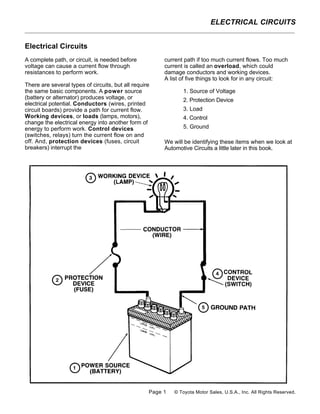
  • 1. ELECTRICAL CIRCUITS Electrical Circuits A complete path, or circuit, is needed before current path if too much current flows. Too much voltage can cause a current flow through current is called an overload, which could resistances to perform work. damage conductors and working devices. A list of five things to look for in any circuit: There are several types of circuits, but all require the same basic components. A power source 1. Source of Voltage (battery or alternator) produces voltage, or 2. Protection Device electrical potential. Conductors (wires, printed circuit boards) provide a path for current flow. 3. Load Working devices, or loads (lamps, motors), 4. Control change the electrical energy into another form of energy to perform work. Control devices 5. Ground (switches, relays) turn the current flow on and off. And, protection devices (fuses, circuit We will be identifying these items when we look at breakers) interrupt the Automotive Circuits a little later in this book. Page 1 © Toyota Motor Sales, U.S.A., Inc. All Rights Reserved.
  • 2. ELECTRICAL CIRCUITS Types Of Circuits There are three basic types of circuits: series, parallel, and series-parallel. The type of circuit is determined by how the power source, conductors, loads, and control or protective devices are connected. SERIES CIRCUIT A series circuit is the simplest circuit. The conductors, control and protection devices, loads, and power source are connected with only one path for current. The resistance of each device can be different. The same amount of current will flow through each. The voltage across each will be different. If the path is broken, no current flows. PARALLEL CIRCUIT A parallel circuit has more than one path for current flow. The same voltage is applied across each branch. If the load resistance in each branch is the same, the current in each branch will be the same. If the load resistance in each branch is different, the current in each branch will be different. If one branch is broken, current will continue flowing to the other branches. SERIES-PARALLEL CIRCUIT A series-parallel circuit has some components in series and others in parallel. The power source and control or protection devices are usually in series; the loads are usually in parallel. The same current flows in the series portion, different currents in the parallel portion. The same voltage is applied to parallel devices, different voltages to series devices. If the series portion is broken, current stops flowing in the entire circuit. If a parallel branch is broken, current continues flowing in the series portion and the remaining branches. Page 2 © Toyota Motor Sales, U.S.A., Inc. All Rights Reserved.
  • 3. ELECTRICAL CIRCUITS SERIES CIRCUITS In a series circuit, current has only one path. All voltage on the other side of the load. The drop or the circuit components are connected so that the loss in voltage is proportional to the amount of same amount of current flows through each. The resistance. The higher the resistance, the higher circuit must have continuity. If a wire is the voltage drop. disconnected or broken, current stops flowing. If one load is open, none of the loads will work. When troubleshooting, then, you can see that more resistance will reduce current and less resistance Use of Ohm's Law will increase current. Low voltage would also reduce current and high voltage would increase Applying Ohm's Law to series circuits is easy. current. Reduced current will affect component Simply add up the load resistances and divide the operation (dim lamps, slow motors). But, increased total resistance into the available voltage to find the current will also affect component operation (early current. The voltage drops across the load failure, blown fuses). And, of course, no current at resistances are then found by multiplying the all would mean that the entire circuit would not current by each load resistance. For calculation operate. There are electrical faults that can cause examples, see page 6 in the Ohms law section. such problems and knowing the relationship Voltage drop is the difference in voltage between voltage, current, and resistance will help (pressure) on one side of a load compared to the to identify the cause of the problem. Page 3 © Toyota Motor Sales, U.S.A., Inc. All Rights Reserved.
  • 4. ELECTRICAL CIRCUITS PARALLEL CIRCUITS In a parallel circuit, current can flow through more the smallest load resistance. This makes sense than one path from and to the power source. The because current can flow through more than one circuit loads are connected in parallel legs, or path. Also, remember that the voltage drop across branches, across a power source. The points each branch will be the same because the source where the current paths split and rejoin are called voltage is applied to each branch. For examples of junctions. The separate current paths are called how to calculate parallel resistance, see page 6. branch circuits or shunt circuits. Each branch operates independent of the others. If one load When troubleshooting a parallel circuit, the loss of opens, the others continue operating. one or more legs will reduce current because the number of paths is reduced. The addition of one or Use of Ohm's Law more legs will increase current because the number of paths is increased. Current can also be Applying Ohm's Law to parallel circuits is a bit reduced by low source voltage or by resistance in more difficult than with series circuits. The reason the path before the branches. And, current can be is that the branch resistances must be combined to increased by high source voltage or by one or find an equivalent resistance. Just remember that more legs being bypassed. High resistance in one the total resistance in a parallel circuit is less than leg would affect component operation only in that leg. Page 4 © Toyota Motor Sales, U.S.A., Inc. All Rights Reserved.
  • 5. ELECTRICAL CIRCUITS SERIES-PARALLEL CIRCUITS In a series-parallel circuit, current flows through The total resistance is then divided into the source the series portion of the circuit and then splits to voltage to find current. Voltage drop across series flow through the parallel branches of the circuit. loads is current times resistance. Current in Some components are wired in series, others in branches is voltage divided by resistance. For parallel. Most automotive circuits are series- calculation examples, see page 6. parallel, and the same relationship between voltage, current, and resistance exists. When troubleshooting a series-parallel circuit, problems in the series portion can shut down the Use of Ohm's Law entire circuit while a problem in one leg of the parallel portion may or may not affect the entire Applying Ohm's Law to series-parallel circuits is a circuit, depending on the problem. Very high matter of simply combining the rules seen for resistance in one leg would reduce total circuit series circuits and parallel circuits. First, calculate current, but increase current in other legs. Very the equivalent resistance of the parallel loads and low resistance in one leg would increase total add it to the resistances of the loads in series. circuit current and possibly have the effect of bypassing other legs. Page 5 © Toyota Motor Sales, U.S.A., Inc. All Rights Reserved.
  • 6. ELECTRICAL CIRCUITS Ohm's Law sample circuits. Current found by dividing voltage by resistance. This can be very helpful when Fast, accurate electrical troubleshooting is easy diagnosing electrical problems: when you know how voltage, current, and resistance are related. Ohm's Law explains the • When the resistance stays the same ... current relationship: goes up as voltage goes up, and current goes down as voltage goes down. A discharged battery • Current (amps) equals voltage (volts) divided by has low voltage which reduces current. Some resistance (ohms) ... I = E ÷ R. devices may fail to operate (slow motor speed). An unregulated alternator may produce too much • Voltage (volts) equals current (amps) times voltage which increases current. Some devices resistance (ohms) ... E = I X R. may fail early (burned-out lamps). • Resistance (ohms) equals voltage (volts) divided • When the voltage stays the same ... current goes by current (amps) ... R ÷ E = 1. up as resistance goes down, and current goes down as resistance goes up. Bypassed devices USING OHM'S LAW reduce resistance, causing high current. Loose connections increase resistance, causing low current. The effects of different voltages and different resistances on current flow can be seen in the Page 6 © Toyota Motor Sales, U.S.A., Inc. All Rights Reserved.
  • 7. ELECTRICAL CIRCUITS SAMPLE CALCULATIONS Ohm's law includes these two ideas: Here are some basic formulas you will find helpful 1. In a circuit, if resistance is constant, current in solving more complex electrical problems. They varies directly with voltage. provide the knowledge required for confidence and thorough understanding of basic electricity. Now what this means is that if you take a component with a fixed resistance, say a light bulb, The following abbreviations are used in the and double the voltage you double the current formulas: flowing through it. Anyone who has hooked a six- volt bulb to a twelve-volt circuit has experienced E = VOLTS this. But it wasn't "too many volts" that burned out I = AMPS the bulb, it was too much current. More about that R = OHMS later. P = WATTS 2. In a circuit, if voltage is constant, current varies • Ohm's Law inversely with resistance. Scientifically stated, it says: "The intensity Of the This second idea states that when resistance goes current in amperes in any electrical circuit is equal up, current goes down. That's why corroded to the difference in potential in volts across the connectors cause very dim lights - not enough circuit divided by the resistance in ohms of the current. circuit." Simply put it means that current is equal to volts divided by ohms, or expressed as a formula, • Watts the law becomes: A watt is an electrical measurement of power or I=E/R work. It directly relates to horsepower. In fact, in the Sl metric standards that most of the world or it can be written: uses, engine power is given in watts or kilowatts. E=IXR Electrical power is easily calculated by the formula: This is important because if you know any two of P=EXI the quantities, the third may be found by applying the equation. For instance, a halogen high-beam headlight is rated or 5 amps of current. Figuring 12 volts in the system, we could write: P=EXI P = 12 X 5 P = 60 watts Page 7 © Toyota Motor Sales, U.S.A., Inc. All Rights Reserved.
  • 8. ELECTRICAL CIRCUITS RESISTANCE That becomes: The effect of individual resistors on the total resistance of a circuit depends on whether the circuit is series or parallel. Which becomes: Series Circuits In a series circuit, the total resistance is equal to the sum of the individual resistors: So there is a little more than one-half ohm resistance in the circuit. You can see that the more SERIES: resistors in parallel, the less the resistance. total R = R1 + R2 + R3 + In fact, the total resistance is always less than the smallest resistor. This is why a fuse will blow if That is the basis of the concept of voltage drop. you add too many circuits to the fuse. There are so For example, if you had a circuit with three loads in many paths for the current to follow that the total series (a bulb, resistor, and corroded ground) you resistance of the circuit is very low. That means would add the three together to get total the current is very high - so high that the fuse can resistance. And, of course, the voltage would no longer handle the load. drop across each load according to its value. B. For two resistors: Parallel Circuits Parallel circuits are a different story. In a parallel circuit, there are three ways to find total For a 3 ohm and a 5 ohm resistor that would be: resistance. Method A works in all cases. Method B works only if there are two branches, equal or not. Method C works only if the branches are of equal resistance. A. The total resistance is equal to one over the C. For several identical resistors, divide the value sum of the reciprocals of the individual of one resistor by the number of resistors, or: resistors. That sounds confusing, but looking at the formula will make it clearer: PARALLEL: Where R1 is the value of one resistor and n is the number of resistors. So if you had three 4 ohm resistors in parallel it would be: n example will make it even clearer. Suppose there is a circuit with three resistors in parallel: 4 ohms, 2 ohms, and 1 ohm. The formula would look like this: Page 8 © Toyota Motor Sales, U.S.A., Inc. All Rights Reserved.
  • 9. ELECTRICAL CIRCUITS Page 9 © Toyota Motor Sales, U.S.A., Inc. All Rights Reserved.
  • 10. ELECTRICAL CIRCUITS ASSIGNMENT NAME: 1. Draw and label the parts of a Series Circuit and a Parallel Circuit. 2. Explain the characteristics of “Voltage” and how it differs between a Series Circuit and a Parallel Circuit. 3. Explain the characteristics of “Current” and how it differs between a Series Circuit and a Parallel Circuit. 4. Explain the characteristics of “Resistance” and how it differs between a Series Circuit and a Parallel Circuit.