SlideShare una empresa de Scribd logo
1 de 59
Descargar para leer sin conexión
…The Legend Rides On…
TECHNICAL SPECIFICATION: -
Bullet 350CC
Engine Single Cylinder Four stroke with over-head                                              Small - 63.03       / Large -
valve                                                               Main shaft ball bearings   62.05
Cubic Capacity                  346 cc                              Final drive sprocket       16 teeth
Stroke                          90 mm                               Rear drive chain           5/8quot; pitch chain
Bore-Nominal                    70 mm                               Brake drum sprocket        38 teeth
Actual                          69.875 mm / 2.751 in.               Carburetor                 Mikcarb-VM-24
Compression Ratio               7.25 : 1                            Main jet                   90
Compression Pressure            110 +- 5 Psi (recommended)          Pilot jet                  25
Engine Output                   18 BHP @ 5625 rpm                   Contact Breaker (Coil ignition)
Torque                          2.74 kgm @ 2875 rpm                 Points gap                 0.14/0.16quot; (0.35 to 0.4 mm)
Piston and Piston Rings                                             Timing before TDC          1/32quot; (0.8mm)
                                                                                               14mm      diameter B7HS
Ring Clearance in grooves       (Dimensions for new components)     Spark plug                 (NGK) or equivalent
Plain (2)                       .001/.003quot;                          Spark plug gap             0.46 to 0.50 mm
Scraper                         .002/.004quot;                          Condenser (Capacitor)      0.18 to 0.25 MFD
Ring end gap in bore            .015/.020quot;                          Suspension
Maximum       Ring      Gap                                                                    Telescopic           hydraulic
Permissible                     0.030quot;                              Front                      damping
Gudgeon pin diameter            0.7498/0.7500quot;                      Stroke                     155 mm
                                                                                               Pivoted fork       with shock
Crank Pin Diameter              1.24875 / 1.249 quot;                   Rear                       absorbers
Connecting rod small end
diameter                        0.7505/.7507quot;                       Wheel Rim Type             WM 2 - 19
Crankshaft                                                          Tyre Size                  3.25 x 19 (Front)
Driving side ball bearing       25 x 62 x 17 mm (6305)              Wheel bearings             3.50 x 19 (Rear)
                                25 x 62 x 17 mm (NU 305 or                                     17 x 40 x 12 mm (6203 or
Roller bearing                  N305)                               (Front & Rear)             6203 ZZ)
                                25 x 52 x 15 mm (NU 205 or NU                                  Mechanical       internally
Timing side roller bearing      205 R)                              Brakes                     expanding shoe type
                                                                                               178 mm x 38 mm Twin
Cam Lift                        0.3125 in                           Front                      leading shoes
                                                                                               153 mm x 25 mm Single
Valve lift                      0.3125 in                           Rear                       leading shoe
Valve timings with 0.012quot; clearance                                 Fuel Tank
Exhaust opens                   75 o BTDC                           Full Tank capacity         14.5 liters
Exhaust Closes                  35 o ATDC                           Reserve capacity           1.25 liters
Inlet Opens                     30 o BTDC                           Oil Capacity and Grades
Inlet Closes                    60 o BTDC                           Oil Tank                   2.25 liters SAE 20 W 50
                                                                                               200 ml on each leg
Rocker Bearings        Inside   0.625 / .626quot; (Dimensions for new                              hydraulic oil or SAE- 10 W
diameters                       components)                         Fork                       30
                                                                                               420 ml approximately SAE -
Rocker spindle diameter         0.6235 / 0.6240quot;                    Clutch                     20 W 40
                                                                                               700 Grams of veedol 00
                                                                                               grease (For topping use
Inlet valve stem diameter       .3425 / .3430quot;                      Gear box                   SAE - 20 W 50)


          Courtesy: RE in Orkut… Formatted & Converted: Nishanth, vonishanth@rediffmail.com
                                http://www.royalenfield.com/nishanthvo
Exhaust     valve       stem
diameter                         .3405 / .3410                       Dimensions
Valve    guide        internal
diameter                         .3437/.3447quot;                        Weight (Dry)               163 kg
Valve    Guide      External
Diameter                         .6270/.6275quot;                        Pay load (Max)             172 kg
Tappet    Guide       internal
diameter                         .3752/.3760quot;                        Ground Clearance           14 cm (140 mm)
Tappet    guide       external
diameter                         .7505/.7510quot;                        Overall length             212 cm (2120 mm)
                                 Dry sump, Oil tank integral with
Lubrication                      the crank case                      Overall width              75 cm (750 mm)
Clutch                           Wet, multiple, oil immersed         Saddle height              85 cm (850 mm)
Engine sprocket                  25 teeth                            Wheel base                 137 cm (1370 mm)
Clutch sprocket                  56 teeth                            Electricals
Primary Drive Chain              3/8quot; pitch Duplex Chain             System                     12 V DC
Gear Box
Overall Gear Ratios              5.32,7.26,9.80 & 14.80


Bullet 500CC

Engine Single Cylinder Four stroke with over-head                                               Small    - 63.03/ Large -
valve                                                                Main shaft ball bearings   62.05
Cubic Capacity                   499 cc                              Final drive sprocket       17 teeth
Stroke                           90 mm                               Rear drive chain           5/8quot; pitch chain
Bore-Nominal                     84 mm                               Brake drum sprocket        38 teeth
Actual                           83.96 mm / 83.97 mm.                Carburetor                 Mikcarb-VM-28
Compression Ratio                6.5 : 1                             Main jet                   110
Compression Pressure             110 +- 5 Psi (recommended)          Pilot jet                  25
Engine Output                    22 BHP @ 5400 rpm                   Contact Breaker (Coil ignition)
Torque                           3.5 kgm @ 3000 rpm                  Points gap                 0.14/0.16quot; (0.35 to 0.4 mm)
Piston and Piston Rings                                              Timing before TDC          1/32quot; (0.8mm)
Ring Clearance in grooves        (Dimensions for new components)     Spark plug                 NGK BR8 ES or equivalent
Plain (2)                        .001/.003quot;                          Spark plug gap             0.46 to 0.50 mm
Scraper                          .002/.004quot;                          Condenser (Capacitor)      0.18 to 0.25 MFD
Ring end gap in bore             .015/.020quot;                          Suspension
Maximum       Ring       Gap                                                                    Telescopic           hydraulic
Permissible                      0.039quot;                              Front                      damping
Gudgeon pin diameter             0.7498/0.7500quot;                      Stroke                     155 mm
                                                                                                Pivoted fork       with shock
Crank Pin Diameter               1.24875 / 1.249 quot;                   Rear                       absorbers
Connecting rod small end
diameter                         0.7505/.7507quot;                       Wheel Rim Type             WM 2 - 19
Crankshaft                                                           Tyre Size                  3.25 x 19 (Front)
Driving side ball bearing        25 x 62 x 17 mm (6305)              Wheel bearings             3.50 x 19 (Rear)
                                 25 x 62 x 17 mm (NU 305 or                                     17 x 40 x 12 mm (6203 or
Roller bearing                   N305)                               (Front & Rear)             6203 ZZ)
                                 25 x 52 x 15 mm (NU 205 or NU                                  Mechanical       internally
Timing side roller bearing       205 R)                              Brakes                     expanding shoe type
                                                                                                178 mm x 38 mm Twin
Cam Lift                         0.3125 in                           Front                      leading shoes
                                                                                                153 mm x 25 mm Single
Valve lift                       0.3125 in                           Rear                       leading shoe
Valve timings with 0.012quot; clearance                                  Fuel Tank
Exhaust opens                    75 o BTDC                           Full Tank capacity         14.5 liters
Exhaust Closes                   35 o ATDC                           Reserve capacity           1.25 liters
Inlet Opens                      30 o BTDC                           Oil Capacity and Grades
Inlet Closes                     60 o BTDC                           Oil Tank                   2.25 liters SAE 20 W 50
                                                                                                200 ml on each leg
Rocker Bearings        Inside    0.625 / .626quot; (Dimensions for new                              hydraulic oil or SAE- 10 W
diameters                        components)                         Fork                       30
                                                                                                420 ml approximately SAE -
Rocker spindle diameter          0.6235 / 0.6240quot;                    Clutch                     20 W 40


          Courtesy: RE in Orkut… Formatted & Converted: Nishanth, vonishanth@rediffmail.com
                                http://www.royalenfield.com/nishanthvo
700 Grams of veedol 00
                                                                                                   grease (For topping use
 Inlet valve stem diameter       .3425 / .3430quot;                       Gear box                     SAE - 20 W 50)
 Exhaust       valve     stem
 diameter                        .3405 / .3410                        Dimensions
 Valve      guide     internal
 diameter                        3437/.3447quot;                          Weight (Dry)                 168 kg
 Valve     Guide     External
 Diameter                        .6270/.6275quot;                         Pay load (Max)               172 kg
 Tappet      Guide    internal
 diameter                        .3752/.3760quot;                         Ground Clearance             14 cm (140 mm)
 Tappet      guide   external
 diameter                        .7505/.7510quot;                         Overall length               212 cm (2120 mm)
                                 Dry sump, Oil tank integral with
 Lubrication                     the crank case                       Overall width                75 cm (750 mm)
 Clutch                          Wet, multiple, oil immersed          Saddle height                85 cm (850 mm)
 Engine sprocket                 25 teeth                             Wheel base                   137 cm (1370 mm)
 Clutch sprocket                 56 teeth                             Electricals
 Primary Drive Chain             3/8quot; pitch Duplex Chain              System                       12 V DC
 Gear Box
 Overall Gear Ratios             5.01,6.83,9.22 & 13.93


DE – CARBONIZING: -
After a few thousand kilometers usage the carbon build up in the engine will cause general falling off in power,
accompanied by increased fuel consumption and starting trouble. De-carbonizing will normally be necessary every 8000
kilometers. This can be carried out without removing the engine from the frame. The mileage between de-carbonizing will
vary from machine to machine depending on the type of usage. A machine used for frequent short journeys will require
more attention that one that is used for long distance touring.

  Removal of the Petrol Tank

     •    Close the petrol tap. Disconnect the petrol hose from petrol tap end.
     •    Remove the two studs which holds the petrol tank to the frame and pull the petrol tank upwards.

  Removal of the Cylinder head

     •    Remove the engine steady eye bolt.
     •    Disconnect the high tension lead from the spark plug. Remove rocker oil pipe.
     •    Remove the exhaust pipe and silencer.
     •    Remove the air filter by undoing the bolts on the side of the air filter body.
     •    Push the carburetor back clear off the nuts after removing the fixing nuts.
     •    Remove the rocker box covers.
     •    Remove the de-compressor cable from the lever end of the handlebar (LH side).
     •    Remove the rocker arms and bearings completely after removing four 3/16quot; nuts on each. Lift out the push rods
          both inlet and exhaust.
     •    Remove the six cylinder head nuts and washers
     •    Lift the cylinder head off the barrel, tapping it gently beneath the exhaust and inlet ports with a wooden mallet.
          Do not tap the fins.


  Removal of Cylinder and Piston


          Courtesy: RE in Orkut… Formatted & Converted: Nishanth, vonishanth@rediffmail.com
                                http://www.royalenfield.com/nishanthvo
•     Slacken the two clamp nuts on the top of the crankcase neck. Remove the 1/4quot; nut above the tappet chest
             and lift the barrel.
       •     Remove the circlip retaining the gudgeon pin on the timing side of piston taking care not to drop the circlip into
             the crank case.
       •     Extract the gudgeon pin using special tool PED 2015 (with adaptor if necessary) so that the piston and the pin
             can be replaced the same way around, ie. split skirt to the front.


  Removal of Valves

  To remove valves from the cylinder head, first lift off the end caps from the valve stems. If these have stuck they can be
  removed with a screwdriver. Using compressing tool PED 2018 ST compress the valves springs from the valve tip.
  Slacken back the compressing tools and release the springs. Withdraw the valve and place its springs, top spring collar,
  bottom collar, the end cap and split conical collars together in order that they may be reassembled with the valve from
  which they were removed. If the valve will not slide easily through the valve guide, remove any slight burrs on the end of
  the valve stem with a carborundum stone or by using a fine jeweler's file to remove any sharp edge or burr. If the burrs
  are not removed and the valve is forced out, the valve guide may be damaged.


  Decarbonizing the Cylinder head - Combustion Chamber

Remove carbon from the valves, ports and combustion chamber by scraping. Take care not to cause any damage to the
valve faces or valve seat inserts. Scrape gently to avoid scoring the cylinder head. DO NOT, under any circumstances, use
caustic soda or potash for the removal of carbon from aluminium alloy. Remove the piston rings carefully. For cleaning the
grooves in the piston, a piece of broken piston ring thrust into a wooden handle and filed to a chisel point can be used.


  Piston and Rings

If the piston rings are in good condition they can be put back, taking care to fit them in their original grooves and the same
way up. If the rings show brown or black patches, or if their gaps are more than specified service limits (Page 79), when in
position in the barrel, new rings should be fitted. The correct gap for new rings are given in the technical specifications
(pages 6 & 8 ) for 350 and 500cc. The gap should be measured in the least worn part of the cylinder, which will be found at
the top or bottom of the bore.


           Courtesy: RE in Orkut… Formatted & Converted: Nishanth, vonishanth@rediffmail.com
                                 http://www.royalenfield.com/nishanthvo
Only for 350cc
The original size of the cylinder bore is 2.751quot; (69.875mm). If the wear at any point in the bore exceeds 0.008quot; the cylinder
should be rebored to 0.020quot; and an oversize piston fitted. (It should be rebored to 0.40quot; after a further 0.08quot; wear). Piston
sizes available are .020quot; and .040quot; oversize. The original side clearance between the piston rings and grooves is 003quot;. If
the grooves show a wear of .005quot; the piston should be replaced.

  Big end bearing inspection

Examine the condition of the big end while the piston is removed. About 0.10quot; - 0.20quot; end float is permissible and it will be
possible to rock the connecting rod slightly. The big end has a floating bush with an original clearance of approximately .
003quot; However, if a DEFINIT E up and down play can be felt engine should be stripped further to have the big-end renewed.


  Valves, Valve Guides and springs

Test the valve guides for wear by trying fit of a new valve in them. Both valves should be quite free, but the exhaust valve
has more clearance (.002quot;) than inlet valve.

To remove the valve guides from the head, two special tools are required which can be easily made. The first is a piece of
tube with an internal bore of not less than 7/8quot;. The second is a mandrel about 4quot; long made from 9/16quot; diameter bar with
the end turned down to 1/3quot; diameter for a length of 1/2quot;. Support the cylinder head on the tube, which fits over the collar of
the valve guide. Using the mandrel, force the guide out of the head with a hand press or by using a hammer.

To fit a new guide, support the head at the correct angle and use a hand press and the same mandrel. If a hand press is
not available, the guide can be replaced using a hammer and a mandrel, to prevent damage to the guide. Check the length
of the valve springs which are originally 2.020quot; and 2.095quot; for the inner and outer springs respectively. If these have
reached the specified service limits they should be renewed.


  Decompressor


          Courtesy: RE in Orkut… Formatted & Converted: Nishanth, vonishanth@rediffmail.com
                                http://www.royalenfield.com/nishanthvo
If the decompressor holds compression and operates freely there is no need to interfere with it except to remove the carbon
from the head of the valve. If the valve is leaking, it will be necessary to regrind it on its seat. This can be done without
completely dismantling it. Having disconnected the control cable from the handle bar, unscrew the decompressor from the
cylinder head. Compress the spring and remove the spring cap.

Unscrew the adjusting screw and locknut from the cable block and pull the cable sideways out of the block. Push the spring
upwards and pull the cable nipple out of the body. It will now be possible to remove the cable and nipple through the spring,
leaving the decompressor body and spring detachedfrom the control cable.

The spring and the cap should now be replaced. The valve may be ground in by applying a thin coating of grinding paste on
the seat of the valve and twisting to and fro by means of the cable block at its upper end and occasionally lifting the valve
from its seat. Do not rotate the valve through a complete revolution before lifting, as this will groove the seat.

After grinding, wash the whole assembly thoroughly in petrol, opening and shutting the valve while doing so. Make sure that
all traces of grinding paste have been removed.

If the paste should get into the cylinder serious damage would be caused. If the valve shows a tendency to stick-up in the
body but otherwise is satisfactory, this can be cured by washing in petrol, though in this case it will not be necessary to
disconnect the control cable.

If the decompressor valve is badly burnt or bent it must be replaced.


  Re-assembly after Decarbonising

Before building up the engine, see that all parts are scrupulously clean and place them on a clean tray, work bench or over
a clean sheet of paper. While re-assembling it is advisable to fit a new gasket between the cylinder barrel and the
crankcase. Smear clean oil over the piston and space the ring gaps. The second ring is a taper ring and is marked TOP on
the upper surface.

  WARNING : This mark should be on top when fitted. Reversing the ring will result in pumping of oil into the
  cylinder and consequent smoking.

Place the piston over the connecting rod small end ensuring the split skirt is facing the front and insert the gudgeon pin.
Secure the gudgeon pin with the circlips. Oil the cylinder bore and gently push barrel over the piston while keeping the rings
compressed in their grooves and seat it gently on the barrel gasket. Refit the 1/4quot; nut above the timing chest. When fitting
the head again, apply jointing compound sparingly on both sides of the gasket. Replace the six nuts and tighten them
progressively and diagonally from one side to the other to prevent distortion.

  WARNING : Excess compound may block oil-ways.

Place the push rods with the adjustable parts downward. The shorter pushrod is the Inlet. Ensure valve stem caps are fixed
on the valve stems. Position the rockers and bearings, making sure that the oil feed holes are at the bottom and that the


          Courtesy: RE in Orkut… Formatted & Converted: Nishanth, vonishanth@rediffmail.com
                                http://www.royalenfield.com/nishanthvo
caps and bases are in line when tightened down. Adjust the push rods after ensuring piston is in TDC on compression
stroke.

The silencer could be cleaned of carbon using a hot caustic soda solution, if necessary.

  NOTE: The cylinder head and base nuts should be checked again for tightness, after the engine has been run long
  enough to get thoroughly warm.

Tighten clamp nuts on crankcase finally. For torque tightening of cylinder head nuts please refer torque chart on page .100


SERVICE OPERATION – ENGINE ON FRAME: -
  Removal of the Timing cover
  First place a tray under the engine to hold the oil which will escape when the cover is removed.

  Remove the exhaust pipe and silencer. Remove ten screws from the timing cover, taking care not to lose the sealing
  washers, one for each screw.

  NOTE: When removing or refitting the timing cover it is important that the engine is gently cranked. This will prevent
  damage of pump worm or the pump spindle.

  Draw off the timing cover, tapping lightly if necessary with a wooden mallet.

  While refitting the timing cover ensure that the joint washer is correctly located over the oil holes, using a little grease (not
  compound) to hold it in position.

  Ensure proper functioning of oil pump by checking oil flow at rocker pipe union when the engine is running at slow speed.

  Slacken the oil pipe banjo union to see the oil flow and clamp it again properly. Wipe off the oil that has oozed out.


          Courtesy: RE in Orkut… Formatted & Converted: Nishanth, vonishanth@rediffmail.com
                                http://www.royalenfield.com/nishanthvo
Cleaning/Replacement of Oil Filter Element - Oil Feed and Return Filters


Overhauling of Oil feed and Return Pumps
•           Remove the timing cover.
•           Remove the end covers from both pumps.
•           Remove the pump discs and plungers.
•           Remove the pump spindle, which can be pulled out only from the front or return pump end.

•          Check the fit of the plungers in the pump discs, which should be sliding fit and should be able to be
moved in and out by hand.


       Courtesy: RE in Orkut… Formatted & Converted: Nishanth, vonishanth@rediffmail.com
                             http://www.royalenfield.com/nishanthvo
When matching a plunger in the pump disc, if it is found to be too tight a fit carefully lap the plunger in the pump disc,
using metal polish until it is just free. If the pump disc is not seating properly in the timing cover, or if a new pump disc
is fitted, it should be ensured that the pump disc matches properly and has a perfect seating in the timing cover. Lap
the discs in the timing cover with fine metal lapping paste or liquid metal polish using special tools PED 2034 ST for
feed pump disc and PED 2035 ST for return pump disc until a fine gray surface is obtained on the pump disc face.


NOTE : Replacement pump discs have a lip left at the opposite side of the lapped face. The purpose of this is
to hold the disc central in the housing during the lapping-in. It should be filed off before the pump is finally
assembled. Care should be taken not to damage the lapped face.

Wash all components and passages thoroughly with petrol after lapping, to remove all traces of grinding paste. Check
the pump disc springs for fatigue by assembling in the timing cover and placing the pump covers in position. The latter
should be held 1/8quot; off the timing cover if the springs are correct. The pump spindle should be renewed if excessive
wear has taken place on the teeth. Reassemble the oil pumps, replacing the cover gaskets. Before fitting each cover
fill the pump chamber with clean oil. Having assembled the pumps, lay the timing cover flat and fill the oil ports using
an oil can. Turn the pump spindle with a screwdriver in a clockwise direction and it can then be checked whether the
pumps are operating correctly. Before replacing the timing cover on the engine, fill the filter chamber with clean oil and
fit the filter element.


NOTE : With the engine running, the oil feed to the big end can be checked by partially unscrewing the feed
plug in the timing cover between the oil pumps. The oil return can be checked by slackening the rocker pipe
banjo bolt on the cylinder head and observing the oil flow.

Removal of Pump Worm and Timing Pinion

Unscrew the pump worm using the hexagon head behind the worm, with special tool PED 2006. Withdraw the
timing pinion using a special tool PED 2013.

CAUTION: The worm nut has a left hand thread. When turned clockwise the worm nut can be loosened and
when turned anticlockwise the worm nut gets tightened.


Valve Timing

The cams are integral with the cam pinions. They have internal sintered iron bushes running on fixed spindles on the
timing chest.

The cams and the timing pinions are provided with timing marks to set proper valve timings. The procedure is detailed
below.

Bring the piston to the TDC position. Match the exhaust cam (provided with two sets of punch marks) with the timing
pinion so that the two punch marks coincide on both. Match the inlet cam to the exhaust cam so that the single punch
mark coincides on both. Push the cams home towards the crankcase.


        Courtesy: RE in Orkut… Formatted & Converted: Nishanth, vonishanth@rediffmail.com
                              http://www.royalenfield.com/nishanthvo
Tappet Adjustment - Cold

It is very essential to ensure that the valves are closed fully during the closing period of the cam. The tappet clearance
should be adjusted properly to achieve this and to cater for a certain amount of thermal expansion of the working
components. We recommend 'NIL' clearance of the tappets to be set at cold. Provision for adjustment is given at the
bottom end of the push rod which sits over the tappet. Access to this is by removing the tappet cover.

Proceed as follows for adjustments. Bring piston to TDC at the end of compression stroke, so that both the valves are at
the closed position. This may be ensured by seeing the valve timing marks if the timing cover is open, or through
ammeter needle movement, when ignition is switched on. Check the push rods. They must rotate thumb free without any
up and down play.

In case the push rods do not rotate freely or if up and down play is noticed, the push rods need to be adjusted.

Loosen the lock nut in the adjuster, by holding the top nut. Thread in or out the bottom adjuster, till the correct push rod
freedom is achieved. Retighten the lock nut after adjustments are complete.


The Clutch - 350cc and 500 cc

The 350cc clutch has five driven plates and four driving plates, including the friction disc on the sprocket.

The 500cc clutch is similar to that of 350cc, except that there are six driven plates and five driving plates.

Also the lugs on the clutch sprocket and the splines on clutch center are longer.

Removal of the Clutch

Remove the L.H. front foot rest, place a tray beneath the primary chain case to collect the oil in the chain case. Remove
the central nut in the chain case outer and remove the cover. To remove the clutch unscrew the clutch spring pins. Lift
away the spring caps, springs, clutch front plate, clutch pad in main shaft, the assembly of driving and driven clutch
plates and the clutch retaining spring. The clutch sprocket can then be withdrawn along with the chain and engine
sprockets (see point 10).

The clutch center can be removed only after the engine sprocket, primary chain and the clutch sprocket have been
removed.


To remove the clutch center hold the clutch with a brake bar (Special tool No PED 2025) and remove the center retaining
nut and washer with a box spanner. The clutch center can then be withdrawn from the shaft using extractor (Special Tool
No. PED 2005).


        Courtesy: RE in Orkut… Formatted & Converted: Nishanth, vonishanth@rediffmail.com
                              http://www.royalenfield.com/nishanthvo
1. Clutch center and back plate            12. Clutch intermediate plate
             assembly                                   (flat)
             2. Clutch sprocket 56 T & Drum             13. Clutch bonded plate
             assembly                                   assembly
             3.Clutch sprocket drum (N/S)               14. Clutch front plate
             4. Clutch sprocket friction disc           15. Clutch spring
             5. Clutch sprocket friction disc rivet     16. Clutch Cap
             6. Clutch sprocket ball cage (N/S)         17. Clutch spring screw
             7. Clutch sprocket ball cage rivets
             (N/S)                                      18. Clutch pad
             8. Clutch sprocket balls(3/16quot; dia)
             (N/S)                                      19. Clutch rod
                                                        20. Washer main           shaft
             9. Clutch retaining spring                 (spring)
             10. Clutch intermediate            plate
             (dished)                                   21. Nut main shaft (Nyloc)
             11. Clutch plate (insert type)


Courtesy: RE in Orkut… Formatted & Converted: Nishanth, vonishanth@rediffmail.com
                      http://www.royalenfield.com/nishanthvo
1. Clutch center and back plate            12. Clutch intermediate plate
                            assembly                                   (flat)
                            2. Clutch sprocket 56 T & Drum             13. Clutch bonded plate
                            assembly                                   assembly
                            3. Clutch sprocket drum (N/S)              14. Clutch front plate
                            4. Clutch sprocket friction disc           15. Clutch spring
                            5. Clutch sprocket friction disc rivet     16. Clutch Cap
                            6. Clutch sprocket ball cage (N/S)         17. Clutch spring screw
                            7. Clutch sprocket ball cage rivets
                            (N/S)                                      18.Clutch pad
                            8. Clutch sprocket balls(3/16quot; dia)
                            (N/S)                                      19. Clutch rod
                                                                       20. Washer main           shaft
                            9. Clutch retaining spring                 (spring)
                            10. Clutch intermediate            plate
                            (dished)                                   21. Nut main shaft (Nyloc)
                            11. Clutch plate (insert type)

  Removal of Engine and Clutch sprockets

Remove the alternator stator by undoing three nuts. The primary chain is endless hence it is necessary to remove both the
engine and clutch sprockets simultaneously. Remove the central hexagon nut securing the alternator rotor, which can then
be drawn off, taking care not to lose the key. The engine sprocket is mounted on splines and can be removed along with
the clutch sprocket using extractor PED 2004 ST.

  Removal of Final Drive Sprocket

Remove the clutch as described above. Remove the primary chain tensioner. Remove the primary chaincase inner by
removing three nuts. Straighten the bent tab of the tab washer, which is provided for locking the final drive sprocket nut.
Hold the sprocket and remove the nut (right hand thread). The sprocket can then be withdrawn.

  Re-assembly of the Clutch Plates

When re-assembling the clutch plates the following order must be observed. The clutch pad must be fitted into the main
drive shaft, plain dished plate (dish projecting outwards). Friction plate with inserts, plain flat plate, friction plate bonded,
plain dished plate (dish projecting inwards), friction plate bonded, clutch front plate, 3 springs on the clutch center lugs.

In the case of 500cc one more plain flat plate will also have to be fixed after the plate with inserts has been assembled.

The other three springs are located by means of bosses on the clutch cap. Tighten the spring pins as far as they will go. If
the clutch lifts un evenly it is probably is that one of the springs has taken a set in which case new springs should be fitted.

The friction plates with inserts should be renewed if badly worn or when the inserts have become loose in their plate. The
bonded friction plates require renewal when worn or charred. ( A light change to blackish color should not be mistaken as
charred). Excessive or premature wear of the platesis due to either running the vehicle at half clutch application or
depriving clutch plates of oil, with insufficient or no oil in the clutch chain case.


          Courtesy: RE in Orkut… Formatted & Converted: Nishanth, vonishanth@rediffmail.com
                                http://www.royalenfield.com/nishanthvo
Primary Chain Adjustments

Access to the primary chain adjuster is gained by removing the primary chain cover, which is held in position by a single
nut. Before removing the nut, place a tray under the engine to collect the oil from the chaincase.

Beneath the bottom run of the chain is a curved slipper chain tensioner pad on which the chain rests. This can be raised or
lowered by turning the adjusting screw below the chain tensioner pad after having first slackened the locknut.

The chain should be adjusted so that there is 1/4quot; up and down movement at the center of the top run of the chain.
Remember to check the chain. Remember to check the chain tension at 3 or 4 places and then adjust accordingly. Ensure
that the chain tensioner pad moves freely and the lock nut of the adjuster is retightened after carrying out the adjustments.
The chain has to be changed if its length has increased by 3/4quot; more than the length of a new chain.

After replacing the chain cover remember to replenish the chaincase with oil (SAE 20) up to the level plug in outer chain
case (approx quantity 430 to 450 ml)


  Adjustment of the Clutch Control

It is essential that there should be about 3 to 4mm free movement in the clutch cable to ensure that all the spring pressure
is exerted on the plates.

There are two points of adjustments on the clutch cable. The first is the midway adjuster at the middle of the cable just
above the chain case. The adjustment is made by screwing the adjuster screw in or out of the adjuster body. Tighten the
locknut on the screwed collar after adjustment has been made.

The other point is at the handlebar end. Loosen the locknut and thread in the adjuster to increase play and vice-versa to
reduce play. Tighten lock nut after carrying out adjustment. However, if the adjusters have reached their maximum position,
then the adjustment can be carried out in the gearbox outer cover. Before proceeding on the adjustment, turn in both cable
adjusters to their fully closed position (fully in position).

To make the adjustment, remove the inspection cover, slacken the locknut and turn the central screw in to get the desired
free play on the clutch lever at the handle bar end. Tighten.

Owing to initial bedding down of the clutch plate inserts, the clutch control may require adjustment after the first few
hundred kms with a new machine. This point should therefore be examined soon after delivery and adjustment made if
necessary. Initially, excessive play in the cable can be taken up through midway adjuster and the adjuster at the handle bar
end.

NOTE : The clutch adjuster ball and clutch rod may require cleaning and greasing around 6000 miles / 10000 kms
usage. To do this, loosen and carefully remove the clutch adjuster from its position, taking care not to drop it into
the gearbox outer cover.

Start the engine and tilt the motorcycle towards the gearbox side, so that the clutch rod can be removed. Wash thoroughly,
the clutch rod and adjuster and look for chipped or worn clutch rod ends and free rotation of the clutch adjuster ball.


          Courtesy: RE in Orkut… Formatted & Converted: Nishanth, vonishanth@rediffmail.com
                                http://www.royalenfield.com/nishanthvo
Smear multipurpose grease on the clutch rod and carefully reassemble in its location. Adjust the adjuster to ensure free
play is maintained on the handle bar end and tighten locknut.


  Fitting the alternator

The alternator consists of two parts, the stator and the rotor. The stator is mounted on to the primary chain case inner by
three studs and nuts.

The rotor, which contains the permanent magnet, is mounted on the end of the drive shaft and is located by a key and
secured by a special nut and spring washer. The designed radial air gap between the rotor and the poles of the stator is
0.25mm (0.010quot;) and care must be taken when refitting to see that it is not less than 0.15mm (0.006quot;) at any point.


Fit the rotor first, making sure that it is located concentrically on the end of the drive shaft. Attention must be given to the
proper seating of the key. Finally secure the rotor with the appropriate washer and nut.

Having fitted the rotor, the stator may then be fitted on to the chain case inner with the coil connections facing outwards.
Replace the shake proof washers and the nuts on the studs and tighten gently. Insert six strips (preferably non magnetic
material) 0.15mm (0.006quot;) thick and 25.4mm (1quot;) wide. Check whether the strips are free in position. If one or more of the


          Courtesy: RE in Orkut… Formatted & Converted: Nishanth, vonishanth@rediffmail.com
                                http://www.royalenfield.com/nishanthvo
strips are not free, gently tap stator (at the opposite end) to centralize the same such that all the strips become free.
Tighten the stator nuts and ensure the strips move freely. Gently crank engine, recheck the strips are free. Repeat this
process at 3 or 4 places and then withdraw the strips.


  Function of Breather

The efficient operation of the breather is of paramount importance to the performance of the engine because it acts as a
non-return valve between the crankcase and the outside atmosphere, causing a partial vacuum in the crankcase and
rocker boxes which prevents the passage of oil into the cylinder. If the breather is not acting efficiently, it may cause
pressure in the crankcase instead of partial vacuum, giving rise to smoking or oiling of the plug.

  Gear Box

The gears, ratchet mechanism etc. of the gearbox can also be serviced without dismantling the engine from the frame.

Please refer page 33 for dismantling the gearbox.


         Courtesy: RE in Orkut… Formatted & Converted: Nishanth, vonishanth@rediffmail.com
                               http://www.royalenfield.com/nishanthvo
REMOVAL OF ENGINE FROM THE FRAME: -
  Removal of the Engine from the Frame

      Disconnect alternator leads.                       viii. Remove the rear chain.
      ii. Disconnect the spark plug cap,
      suppressor cap.                                    ix. Remove the footrest (L.H.).
      iii. Turn off petrol tap and disconnect the fuel
      pipe.                                              xi. Support the engine on a suitable box or wood block.
      iv. Remove carburettor assy. along with
      throttle cable.                                    xii. Remove the center stand and the stand stop.
                                                         xiii. Remove the front engine plates and the small bolt fixing
      v. Remove the air filter assy.                     the stand spring bracket and fix rear mudguard.
                                                         xiv. Remove the stud securing the rear engine plate to the
      vi. Remove the exhaust pipe and silencer.          frame.
      vii. Disconnect the engine steady bolt.            xv. Slide out the engine.


  Removal of the Gearbox

Remove the primary chain case outer, clutch assembly, stator and rotor, engine sprocket and clutch sprocket. Remove the
clutch centre and chain case inner.

Remove four 3/8quot; nuts and the gearbox can then be withdrawn from the engine.

  Dismantling the Crankcase

Drain the oil tank by removing the feed and return filter assembly plugs located in the crankcase bottom.
Having removed the engine from the frame dismantle the cylinder head, barrel, piston, timing gear etc., as described in the
chapter quot;Decarbonisingquot;.

Remove the nuts on the driving side of the engine from four fixed studs at the rear of the crankcase.
Remove six studs passing through the crankcase by undoing nuts.

The two halves of the crankcase can then be separated.

The driving side outer race of bearings will remain in the driving side half of the crankcase.

The driving side bearing inner race and the inner distance piece will remain on the engine shaft. ( Crankshaft)
The flywheel assembly may be removed from the driving side of the crankcase.

  Removal and Reassembly of main bearings

Clean the crankcase thoroughly as any trace of oil in the crankcase will burn and discolor the bearing race while heating the
crankcase.

Heat the crankcase in an oven or apply the naked flame of a blow lamp on the circumferential area of the bearing boss and
not directly on the bearing race. When the crankcase gets heated up fairly, about 110º-120ºC, tap the crankcase on a
wooden block (with the bearing race facing downwards) gently so that it will drop down due to the expansion of the bearing
boss.

Remove the circlip from the driving side crankcase and reheat to remove the ball bearing.

Inspect the bearings before assembly. The bearing should spin smoothly. Rotated dry, it may appear to be slightly noisy but
there should be no signs of corrosion, nor must there be any appreciable radial slackness. The outer race of the roller
bearing must be preferably smooth and bright with no evidence of crack or pitting. The individual rollers must show no signs
of wear and should rotate smoothly in the cage. It is recommended to replace with new bearings once they are removed
from the crankcase.

Reheat the crankcases to reassemble the bearings in the crankcase. Assemble the ball bearings in the D/S crankcase after
fitting the circlip. Locate the other circlip, distance tubes outer and inner and then assemble the roller bearing outer race.

Ensure that the bearings are seated properly in the crankcase and the outer roller race is flush with the crankcase.


          Courtesy: RE in Orkut… Formatted & Converted: Nishanth, vonishanth@rediffmail.com
                                http://www.royalenfield.com/nishanthvo
Replacement of the Cam Idler Spindles

When wear is noticed or step formation seen on the spindle, it should be replaced. To remove the cam spindle, heat the
crankcase and tap the spindles out from inside.

To remove the idler pinion spindles, heat the crankcases as before, hold the spindles in a vice and tap the crankcase lightly
with a nylon/wooden hammer.

To replace the cam spindles, locate the spindles in respective holes in the timing side crankcase and drive the spindles in
home with a small hammer (1/2 lb.) and a drift. Make sure that the spindles are upright and parallel to each other.

  Connecting Rod

Wear in the hardened steel big end bush will be shown by a formation of a ridge round the centre of the bearing surface
corresponding with the oil groove in the white metal floating bush. If this wear is excessive, the connecting rod should be
replaced.

Excessive wear on the small end of the connecting rod can be easily seen. The Gudgeon Pin will show a rocking motion if
wear is excessive.


The flywheel assembly consists of the crankshaft and the connecting rod.


          Courtesy: RE in Orkut… Formatted & Converted: Nishanth, vonishanth@rediffmail.com
                                http://www.royalenfield.com/nishanthvo
To dismantle the crankshaft remove the set screws securing the crankpin nuts. Holding the crankshaft in a special jig (PED
2037) remove the crankpin nuts.

Using PED 2037 with a pair of steel bars (about 1quot; x 3/8quot; x 9quot; long) placed across between the flywheel disc, press out the
crankpin using a hand press.

The connecting rod can then be removed along with floating bush.

Turn the crankshaft over in the jig and repeat with other side if necessary.

To remove the timing shaft, remove the set screw from the shaft nut and unscrew the nut. Drive the shaft out with a
hammer and drift. To replace the timing side shaft, reverse the above process, making sure that the key is a good fit and
that the nut is tightened securely by means of a box spanner with a 12quot; tommy bar.

The driving shaft has no nut but is secured by tightening the sprocket nut after the assembly of the engine. It should be
pressed in with a hand press or a hammer and drift. If the latter is used, care must be taken not to damage the centre. It
has a collar which butts against the flywheel disc.

To reassemble the crankshaft, press the crankpin into the timing side flywheel, making sure that the oil hole is in the correct
position and the thrust washer is facing the right way, i.e. with Chamfer away from the flywheel.

Test the oil passages using an oil can to make sure that they are clear.

Assemble the floating bush over the crankpin.

Assemble the connecting rod over the floating bush and smear with engine oil.

Place the other thrust washer over the crankpin, also with the Chamfer away from the flywheel.

Use a brass drift and hammer for pressing the D/S flywheel.

Locate the flywheel in the assembly jig, to ensure that the flywheels and shafts are in line, and replace the nuts. Tighten
securely and refit the set screws.

Test the oil passages again to ensure that they are clear.

If the same crankpin has been put back, it will be necessary to drill out the old grub screw in order to clean the oil passages
after which a new grub screw must be fitted.

Mount the crankshaft between the centers of a lathe or on a pair of vee block and true up to 0.001quot; on either side of the
shafts.

If the readings for the two shafts are high on opposite sides, the error can be corrected by gently tapping either or both of
the flywheels.

If the readings are high on the same side of the two shafts, it is probably due to dirt or foreign matter in the joints and the
crankshaft should be dismantled again, carefully examined and reassembled.


          Courtesy: RE in Orkut… Formatted & Converted: Nishanth, vonishanth@rediffmail.com
                                http://www.royalenfield.com/nishanthvo
RE- assembly of crankcase

  Replace the bearings, etc., in the crankcase halves after heating the crankcase as described earlier. (Refer page 29)

  Fit the inner distance piece in the driving side crankcase.

  Fit the thrust washer on the drive shaft. Fit the bearing inner race on the drive shaft. Assemble the flywheel into the
  bearing. If necessary use the sprocket nut with a suitable spacer to draw the driving shaft through the inner race of the
  ball bearing.

  Make sure that the crankcase face is clean and apply jointing compound to it and fix the crankcase gasket in position.

  Put the thrust washer on the timing side shaft and press the bearing inner race.

  Place the timing side crankcase in position over the flywheel and gently tap with wooden mallet.

  Bolt the two halves of the crankcase together making sure that the joint matches correctly so that the cylinder base is flat.

  Rotate the drive shaft by hand and check for free rotation to ensure correctness in assembly and press the oilseal on to
  the drive side of the crankcase from outside, ensuring proper seating.

  For 500cc

  Press the oil seal onto the timing side of the crankcase and ensure proper seating.


 Dismantling the Gearbox


       Courtesy: RE in Orkut… Formatted & Converted: Nishanth, vonishanth@rediffmail.com
                             http://www.royalenfield.com/nishanthvo
The gearbox can be completely dismantled with the engine in the frame except for the removal of the inside operator and
the bearings in the gearbox case. Remove the kickstarter crank, the gear change lever and the neutral finder. Remove the
top and bottom small inspection covers and disconnect the clutch cable, after loosening clutch adjuster.

Remove four screws and the gearbox outer cover can then be detached. Remove the foot control plate assembly and foot
control by taking off the two nuts securing it. Remove the mainshaft bearing cover which is attachedby two screws.

CAUTION: Hold the kickstarter return spring eyelet by means of a long screwdriver to prevent it from
rebounding (and causing damage) while the mainshaft bearing cover screw is removed.

The mainshaft can be drawn straight out. If the clutch has been removed which, however, should be done before taking off
the gear box inner cover, the top gear pinion and dog will come away with the mainshaft.


GEAR BOX: -
  Dismantling the Gearbox

The gearbox can be completely dismantled with the engine in the frame except for the removal of the inside operator and
the bearings in the gearbox case. Remove the kickstarter crank, the gear change lever and the neutral finder. Remove the
top and bottom small inspection covers and disconnect the clutch cable, after loosening clutch adjuster.


Remove four screws and the gearbox outer cover can then be detached. Remove the foot control plate assembly and foot
control by taking off the two nuts securing it. Remove the mainshaft bearing cover which is attachedby two screws.


    CAUTION: Hold the kickstarter return spring eyelet by means of a long screwdriver to prevent it from
    rebounding (and causing damage) while the mainshaft bearing cover screw is removed.

     The mainshaft can be drawn straight out. If the clutch has been removed which,
     however, should be done before taking off the gear box inner cover, the top
     gear pinion and dog will come away with the mainshaft.


  Removal of the Ball Bearings.

The main shaft ball bearings can be removed by using a stepped drift of 0.437quot;(11mm) & 1.171quot;(29.77mm) in diameter for
the bearing in the case and 0.812quot;(20.64 mm) & 0.515quot; (13.1 mm) in diameter for the bearing in the cover.

When refitting the bearing stepped drifts of 2.31quot; (58.7 mm) & 1.171quot; (29.7 mm) diameter and 1quot; (25.4 mm) in diameter,
must be used for bearings in the case and cover respectively.

  Gear Change Mechanism

If the two pins securing the gear change ratchet mechanism are slackened, the adjuster plate can be set in the desired
position. In this position the movement of the gear lever, necessary to engage the ratchet teeth, will be approximately the
same in each direction.


         Courtesy: RE in Orkut… Formatted & Converted: Nishanth, vonishanth@rediffmail.com
                               http://www.royalenfield.com/nishanthvo
If the plate is incorrectly adjusted, it may be found that, after moving top to third or from bottom to second gear, the outer
ratchets will not engage the teeth on the inner ratchets correctly.

When fitting new parts, if it is found that the gears do not engage properly, ascertain whether a little more movement is
required or whether there is too much movement so that the gear slips right through second or third gear into neutral. If
more movement is required, even after adjusting the adjuster plate then this can be obtained by filing the foot control stop
plate very slightly at the points of contact with the pegs on the ratchet ring. If too much movement is already present, a new
foot control stop plate giving less movement must be fitted.


  Gear box with Continental controls.

The procedure for dismantling the gearbox with Continental controls is the same as described earlier.

While dismantling the gear change mechanism care should be taken to disconnect the foot control lever from the gear shift
shaft after loosening the hex bolt.

The circlip provided on the gear shift shaft should also be removed prior to removing the inner cover.

Grease nipples are provided on the shift shaft and gear lever on the left side of the motorcycle for periodical greasing to
ensure smooth operation of shift shaft and gear lever.

If excessive gear lever travel is noticed and gear engagement becomes difficult, the plastic bushes provided at the gear
linkages are worn out and will have to be replaced with new bushes to reduce play in the linkages.


          Courtesy: RE in Orkut… Formatted & Converted: Nishanth, vonishanth@rediffmail.com
                                http://www.royalenfield.com/nishanthvo
1. Gear box case with bush            36. Plunger spring              71. Clutch lever
2. Gear operator pin                  37. Stop plate bolt             72. Clutch lever grease nipple
3. Bush gear operator pin             38. Stop plate                  73. Clutch lever bearing cap


        Courtesy: RE in Orkut… Formatted & Converted: Nishanth, vonishanth@rediffmail.com
                              http://www.royalenfield.com/nishanthvo
74. Clutch lever bearing block pin
 4. Drive sprocket (16-T)                        39. Washer oil level plug               (1/4quot; x 3/16quot;)
                                                                                         75. Clutch lever adjuster with screw
 5. Lock washer (D/sprocket)                     40. Oil level plug                      & ball
 6. Lock nut felt washer                         41. Washer oil filler & drain plug      76. Nut clutch lever adjuster
 7. Lock nut (D/sprocket)                        42. Oil filler & drain                  77. Neutral lever eccentric bush
 8. Drive sprocket distance piece                43. End cover with bush                 78. Neutral lever stop pin
                                                                                         79. Clutch adjustment inspection
 9. Oil seal                                     44. Bush foot control operator shaft    cap
 10. Main shaft ball bearing (Large)             45. Washer gear box case joint          80. Inspection pin short
 11. Main shaft low gear pinion (25T)            46. Foot operator shaft with lever      81. Neutral lever
 12. Main shaft sleeve                           47. Gear box cover bolt                 82. Cap pin (long)
 13. Sliding gear (21T & 18T)                    48. Gear box cover screw                83. Gear indicator
 14. Main shaft                                  49. Main shaft ball baring (small)      84. Washer for neutral lever spring
 15. High gear pinion dog                        50. Oil thrower (outer) main shaft      85. Neutral lever spring
                                                 51. Main shaft nut (LH thread) (F/s
 16. High gear pinion (15T)                      end)                                    86. Spring cap
 17. Oil thrower (inner)                         52. Ball bearing cap                    87. Neutral lever securing pin
 18. F/s spindle distance washer                 53. K/s return spring                   88. Foot change lever
 19. Lay shaft high gear & K/s wheel (25T)       54. Cap pin (Long)                      89. Pinch bolt & nut
 20. Third gear pinion (22T)                     55. Cap pin (Short)                     90. Foot change lever rubber
 21. Second gear pinion (19T)                    56. F/c lever return spring             91. Bolt kick starter crank
 22. Layshaft                                    57. Adjuster plate                      92. Kick starter crank
 23. Low gear pinion (15T)                       58. Spring stop                         93. Nut kick starter crank bolt
 24. Splined bush                                59. F/c ratchet spring                  94. Rubber kick starter crank
 25. Bush (case end)                             60. F/c plate spring stop               95. Kick starter pedal pall
 26. Gear operator fork                          61. Ratchet operating pin               96. Kick starter pedal
 27. Nut gear operator (inside)                  62. F/c plate                           97. Kick starter pedal pivot pin
 28. Washer gear operator selector               63. Ratchet (outer)                     98. Kick starter pedal spring
 29. Gear operator selector assembly             64. F/c plate pin bush                  99. Drive sprocket (17T) for 500cc
 30. Gear operator (inside)                      65. F/c adjuster plate pin
 31. F/s spindle quot;Oquot; ring                        66. F/c Ratchet (inner)
 32. F/s spindle with bush                       67. F/c stop plate & spring retainer
 33. Layshaft bush                               68. Nut (foot control adjuster plate)
 34. Foot starter pawl                           69. F/c lever short (inside)
                                                 70. F/c cover c/w Clutch lever,
 35. Plunger                                     bearing cap & pins


    Note : F/s means Foot Starter, F/c means Foot Control


  Adjustment of the Neutral Finder

The neutral finder is adjusted by means of an eccentric stopper secured to the front of the gearbox cover by a bolt which
limits the travel of the operating pedal. Slacken the bolt and turn the eccentric stopper until the correct movement of the
pedal is obtained.


          Courtesy: RE in Orkut… Formatted & Converted: Nishanth, vonishanth@rediffmail.com
                                http://www.royalenfield.com/nishanthvo
Lubrication of the Gearbox

Current machines have the gearbox filler plug at the top of the box and a level plug at the rear. Remove both plugs and fill,
with the machine on level ground until the oil commences to flow from the level plug.

Check the level every 800 to 1600 km when the gearbox is warm. For initial filling up of gearbox VEEDOL 'OO' grease is
recommended. During routine maintenance, topping up may be done with SAE 50 oil. The capacity is 700 grams (approx.)
of 'OO' grease mixed with SAE 50 grade oil to a thick consistency.


L U B RICATION: -
Lubrication system is by Dry Sump and effected by an automatic and positive double action oil pumps.

The oil tank is integral with the crankcase, for ensuring the full rate of oil circulation immediately when the engine is started
and for rapid heating of the oil in cold weather. The capacity of the oil sump is 2.25 Ltrs. (SAE 50 grade). There are two
piston type oil pumps running at 1/12 of engine speed positively driven by the worm gear on the timing shaft.

The feed pump is at the rear of the timing cover (Left side when viewed from the front) and pumps oil from the oil tank,
through the oil filter to the big end through the timing shaft. After lubrication of the big end bearings, the oil splashes and
lubricates the cylinder barrel walls and drains to the bottom of thecrankcase.

The return pump (front sied of the timing cover) draws the oil from the crankcase through the drilled passaage and passes
through the rocker oil pipe and lubricates the rocker bearings and valve spring mechanism and flows down through the
push rod tunnels into the timing cover chest.

From here, the drained oil is pumped back to the oil tank through a hole (drilled in the RH crankcase) by the two idler
pinions. The return pump has a capacity of approximately double that of the feed pump, which ensures that oil does not
accumulate in the crankcase. If allowed to accumulate it will lead to smoke – oil splash through breather pipe and starvation
of oil to rocker arm bearings.

Both pumps are double acting, but two sides of feed pump are inter-connected, thereby giving an augmented and even
supply to the big end. Return pump is also inter-connected for effective scavenging from crankcase.

Gauze strainers are provided for both feed and return filters from the crankcase to ensure oil is free from dirt and sludge.

Oil Filter: The oil filter has a special and important feature in design. In the case of clogged filter or should it be neglected
the oil pressure will lift the spring and cap off of its seat, thereby automatically by-passing the filter so that the big end
bearings will not be deprived of lubrication, even though the oil may be dirty.


          Courtesy: RE in Orkut… Formatted & Converted: Nishanth, vonishanth@rediffmail.com
                                http://www.royalenfield.com/nishanthvo
FE ED PUMP

PORTS IN THE TIMING COVER

   Y – Suction from Oil tank

   X – Delivery to big end

   Position 1: The plunger A is drawn out of the feed pump disc C, by the peg B in the spindle D, due to its rotation.

   The suction port T in the pump disc aligns with the suction port Y in the timing cover and oil from the tank is drawn into
   the pump disc as the plunger is drawn out

   Simultaneously, the through hole W in the disc registers with the delivery port in the timing cover.

   The outward movement of the plunger forces the accumulated oil in the annular space in the timing cover to be delivered
   to the big end bearings through the oil filter element.


 FE ED PUMP

PORTS IN FEED PUMP DISC

   T – Suction port

   R – Delivery port

   W, Z – Through holes

   Position 2 : As the pump spindle rotates further the plunger A is pushed into the pump disc C.

   The delivery port R in the pump disc registers with the delivery port X in the timing cover. The oil in the pump disc is
   forced out through these ports, by the plunger for supply to the oil filter element and to the big ends.

   Simultaneously the through hole Z, in the pump disc registers with the suction port Y in the timing cover and draws oil
   from the tank, into the annular space in the timing cover, due to inward movement of the plunger into the disc.


        Courtesy: RE in Orkut… Formatted & Converted: Nishanth, vonishanth@rediffmail.com
                              http://www.royalenfield.com/nishanthvo
RE TU R N PUMP

PORTS IN THE TIMING COVER

    Y' - Suction from Crankcase

    X' - Delivery to Rockery

    Position 1:- The plunger A' is drawn out of the return pump disc C' by the peg B on the spindle D, due to its rotation.

    The suction port T' in the pump disc registers with the suction port Y in the timing cover and oil from the crank case is
    drawn into the pump disc as the plunger is drawn out.

    Simultaneously, the through hole W' in the disc registers with the delivery port X in the timing cover.

    The movement of the plunger forces the accumulated oil in the annular space in the timing cover to be delivered to the
    cylinder head.


  RE TU R N PUMP

PORTS IN THE RETU RN PUMP DISC

    T' - Suction Port
    R' - Delivery Port
    W', Z' - Through holes

    Position 2 :- As the pump spindle rotates further the plunger A' is pushed into the pump disc C'.

    The delivery port R' in the pump disc registers with the delivery port X' in the timing cover. The oil in the pump disc is
    forced out through these ports, by the plunger, for supply to the cylinder head.

    Simultaneously, the through hole Z' in the pump disc registers with the suction port Y' in the timing cover and draws oil
    from the crank case chamber into the annular space in the timing cover due to inward movement of the plunger into the
    disc.


  Description of Frame

The frame is built of special cold drawn welded steel tubing incorporating reinforcements wherever necessary, for extra
strength.


         Courtesy: RE in Orkut… Formatted & Converted: Nishanth, vonishanth@rediffmail.com
                               http://www.royalenfield.com/nishanthvo
The swinging arm unit forms the chainstay and is fitted with rubber bonded silent-bloc bushes. The swinging arm unit is
secured to the main frame by a long bolt passing through the pivot lugs.

  Removal of Rear Spring Box Unit / Servicing Rear Spring Box

Remove the top pivot pin nut, drive out the pivot pin, then hinge the suspension unit back on the lower pivot pin. After
removing the lower nut, the unit may be pushed off the pivot pin welded to the fork end. It is a sealed unit and the internal
mechanism cannot be serviced. Outer dust cover can be removed using special tool PED-2039 for cleaning coil spring.


  Removal of Swinging Arm Chain Stay

Remove the rear wheel, chain, rear sprocket and brake cover plate assembly from the swinging arm chain stay. Remove
one of the pivot nuts and pull the pivot pin from the other end. The chainstay can then be pulled out of the frame.

The life of the rubber bonded silent-bloc bushes is very high. But if it is necessary to replace the bushes, the inner sleeves
will have to be pressed out first on a press. The rubber can than be taken away from the outer sleeves by pliers. The outer
sleeves can be driven out by means of a hammer and a suitable drift.

Replace the rubber bonded bushes in the swinging arm, using a suitable drift, press one bush from one end of the pivot
bearing tube under a press, until the metal outer sleeve is flush with the end face of the pivot bearing tube. While pressing,
it must be ensured that pressure is exerted only on the outer sleeve and not on the inner sleeve of the bush, as axial
pressure on the inner sleeve would destroy the bonding of the rubber to the metal sleeves. Similarly press the second bush
from the other side of the pivot bearing tube until the metal outer sleeve is flush with its end face.

While assembling the swinging arm fitted with rubber bonded silent-bloc bushes to the frame, the pivot nuts should be fully
tightened only with the swinging arm positioned in the mid-stroke of the spring boxes, i.e., when the centre distance
between the spring box top mounting hole in the frame and the bottom mounting pin on the swinging arm is 9.75quot;. This is
recommended so that the rubber bush will be subjected to minimum angular movement in either direction from the mid
stroke.


          Courtesy: RE in Orkut… Formatted & Converted: Nishanth, vonishanth@rediffmail.com
                                http://www.royalenfield.com/nishanthvo
Centre Stand

To remove the centre stand take out the split pins & washers from both the ends of the stand spindle. Drift out the spindle
and withdraw the stand complete after disconnecting both the ends of the stand springs.


         Courtesy: RE in Orkut… Formatted & Converted: Nishanth, vonishanth@rediffmail.com
                               http://www.royalenfield.com/nishanthvo
FRONT FORK: -

Description

The telescopic fork consists of two legs each of which comprises a main tube of alloy steel tubing which is screwed into the
casquette fork head at the upper end and securely clamped to the fork crown. Fitted over the lower end of the main tube is
the bottom tube made of high strength aluminum alloy with an integral lug which carries the wheel spindle. Fitted on the
lower end of the main tube is a steel bush which is a close fit in the bore of the bottom tube. The upper end of the bottom
tube carries a cast iron bush which is a close fit over the outside diameter of the main tube. These bushes are not fitted to
the latest Front fork Assemblies. The bush is secured to the bottom tube by means of a threaded housing which contains
two oil seals. A stud known as the 'Spring Stud' is fitted in the lower end of the bottom tube and a valve port is secured to
the lower end of the main tube. As the fork operates, oil is forced between the spring stud and the bore of the valve port
forming a hydraulic damping system. A compression spring is fitted inside the main tube between the upper end of the main
tube. The lower end of the main tube and the upper end of the bottom tube are protected by a cover secured to the fork
crown.


  Operation of the Fork

The fork provides a range of movement of 150mm/ 6quot; from the fully extended to the fully compressed position. The
movement is controlled by the compression spring and by the hydraulic damping system. The hydraulic damping is light on
the bump stroke and heavier on the rebound stroke, thus damping out any tendency to pitching or oscillation without
interfering unduly with the free movement of the fork when the wheel encounters an obstacle or pot hole.

The fork is filled with a light oil (S.A.E 30) to a point above the lower end of the spring so that the damper chamber 'B' is
always kept full of oil. Upward movement of the wheel spindle forces oil from the lower chamber 'A' through the annular
space between the spring stud and the bore of the main tube valve port into the damper chamber 'B'. During this stroke the
pressure on the underside of the valve plate causes it to lift so that oil can also pass from 'A' to 'B' through the eight holes
in the valve body. Since, however, the diameter of chamber 'B' is less than that of chamber 'A' there is no room in 'B' to
receive all the oil which must be displaced from 'A' as the fork operates. The surplus oil passes through the cross hole in
the spring stud and up the centre hole in the stud, spilling out through the nut which secures the upper end of the spring
stud to the lower end of the fork spring.

On the stroke, the oil in the damper rebound chamber 'B' is forced through the annular space between the spring stud and
the bore of the main tube valve port. During this stroke pressure in chamber 'B' closes the two disc valves at the upper and
lower ends of the chamber so that the only path through which the oil can escape is the annular space between the spring
stud and the port. Damping on the rebound stroke is therefore heavier than on the compression stroke. At the extreme end
of either pump or rebound stroke a small taper portion on the spring stud enters the bore of the valve port, thus restricting
the annular space and increasing the amount of damping . At the extreme end of the bump stroke, the larger diameter taper
on the oil control collar enters the main counter bore of the valve port thus forming a hydraulic cushion to prevent metal to
metal contact.


          Courtesy: RE in Orkut… Formatted & Converted: Nishanth, vonishanth@rediffmail.com
                                http://www.royalenfield.com/nishanthvo
Dismantling the Fork

Place the machine on the centre stand, disconnect the front brake control cable & speedometer connection and remove the
front wheel and mudguard complete with stays. Unscrew the bottom spring and the stud nut which will allow oil to run out of
the fork down to the level of the cross hole in the spring stud.

Now knock the spring stud upwards into the fork with a soft mallet, thus allowing the remainder of the oil to escape. Pull the
fork bottom tube down as far as possible, thus exposing the oil seal housing. In the latest version the oil seal housing is
eliminated and the oil seals are provided as an integral part of the bottom tubes. Hence by pulling the bottom tube
downwards it can be removed from the fork main tubes. [For old type front forks: Unscrew this housing by means of a
spanner on the flats with which it is provided. The bottom tube can now be withdrawn completely from the main tube leaving
the bottom tube bush, oil seal housing and oil seal in position on the main tube.

Now unscrew the main tube valve port using special tool PED 2026.The spring stud and spring can now be withdrawn from
the lower end of the main tube.
NOTE : In the latest version the oil seal housing and steel bush has been eliminated on introduction of integral oil
seals in the bottom tubes.

The steel main tube bush can now be tapped off the lower end of the tube, if necessary using the bottom tube bush for this
purpose. Before doing this, however, it is advisable to mark the position of the bush with a pencil so as to ensure re-
assembling it in the same position on the main tube. The reason for this is that these bushes are ground to size, after fitting
on to the tubes, so as to ensure concentricity. After removal of the main tube bush, bottom tube bush and oil seal housing,


          Courtesy: RE in Orkut… Formatted & Converted: Nishanth, vonishanth@rediffmail.com
                                http://www.royalenfield.com/nishanthvo
the main tube can be removed using tool PED 2036ST. Before attempting to loosen the main tubes, ensure that the 2 pinch
bolts on the fork crown bottom have been successfully loosened to allow the main tubes to rotate.


  Spring

The free length of the spring is 20 1/2quot;. The spring should be replaced if it has closed by more than 1 inch.

  Re-assembly

When refitting the oil seal, or fitting a new one, great care must be exercised not to damage the synthetic rubber lip which
forms the actual seal.

NOTE : Only for Old Type Forks): If the oil seal housing has been removed from the upper end of the main tube and
is refitted from this end, a special nose piece must be fitted over the threaded end of the tube to prevent damage to
the oil seal.

The spring stud is a tight fit in the hole at the lower end of the bottom tube. Once the stud has been located in the hole,
push the bottom tube up sharply against the spring until two or three threads on the stud project beneath the end of the
bottom tube. Now fit the nut and washer and pull the stud into position by tightening the nut. If necessary fit the nut first
without the washer until sufficient thread is projecting to enable the washer to be fitted.

  Removal of complete fork Assembly

The fork complete with the front wheel and mudguard can be removed from the machine, if necessary, by adopting the
following procedure. The leads to the lighting switch and ammeter should be disconnected at their lower ends or by means
of the plug and socket connectors where these are provided.

Disconnect the speedometer drive from the speedometer head.

Remove the two plug screws and loosen the steering head clip bolt and the fork crown clamp bolts.

Unscrew the fork main tubes from the headlamp casing and the steering stem locknut from the top of the steering stem,
turning each tube and the nut a turn or two at a time. When the nut has been removed from the steering stem and the main
tubes have been completely unscrewed from the headlamp casing, the complete fork and wheel with the steering stem can
be removed.

  Lubrication

The lubrication of the fork internal parts is effected by the oil which forms the hydraulic damping medium. All that is
necessary is to keep sufficient oil in the fork to ensure that the top end of the bottom spring stud is never uncovered even in
the full rebound position. The level of oil in the fork can be gauged by removing the top plug screw and inserting a long rod
about 3/8quot; in diameter. If slightly tilted this will wedge against the nut at the upper end of the bottom spring stud. If the oil is
above the spring stud, it will leave a trace on the long rod, which can be seen on removal. This trace of oil implies that oil
level is correct. If the fork is empty to start with, the quantity required is 200ml in each leg. Recommended grade of oil is
hydraulic oil or SAE 10 W 30.

SEQUENCE FOR ADJUSTMENT
   1.  Loosen the Head lamp casing clip bolt by using an Allen Key (size 5mm)
    2. Loosen the front fork crown clip bolts (2 Nos.)
    3. Then screw down the steering stem lock nut by 1/2 thread to 3/4 thread initially and check the play once again. If
       necessary further tightening can be done.
    4. NOTE : Over tightening of this steering Stem lock nut will result in vehicle drag.


          Courtesy: RE in Orkut… Formatted & Converted: Nishanth, vonishanth@rediffmail.com
                                http://www.royalenfield.com/nishanthvo
Lubrication-Steering Head

   The steering head races and stand pivot bearing should be well greased on assembly. No nipples are provided for the
   steering head as experience has shown that the provision of nipples at this point causes trouble through chafing and
   cutting of control and lighting cables. If the steering head bearings are well packed with grease initially they will last for
   several years or many thousands of kilometers.


WHEEL S : -

 Removal from Fork

   To remove the front wheel from the fork place the machine on the centre stand with sufficient packing beneath the
   stand to lift the front wheel clear off the ground when the vehicle is tilted back. Slacken the brake cable adjustment
   and disconnect the cable from the handlebar lever and from the operating cam lever on the hub.

   Disconnect speedometer driving cable. Unscrew the four nuts securing the fork lug caps and allow the wheel to drop
   forward out of the front fork. Make sure that the machine stands securely on the rear wheel and centre stand. If
   necessary, place a weight on the dual seat or a strut beneath the front end of engine near frame down tube to ensure
   this.

   Dismantling

   Lock the brake 'on', by applying the front brake and unscrew the cover plate nut. (For front brake with twin leading
   shoes loosen the lock nuts on the link rod and turn link rod so that both brake shoes become free and are not in
   contact with the brake drum). The cover plate assembly can then be withdrawn from the brake drum.

   The brake shoes can be removed after detaching the return springs. Brake linings are supplied in pairs and are of
   'Bonded' type hence linings cannot be separated and re-fixed with new linings.

   To remove the operating cam unscrew the nut, which secures the operating lever to the splines on the cam. A sharp
   tap on the end of the cam spindle will now free the lever, after which the cam can be withdrawn from its housing. The
   brake shoe pivot pin can be removed after unscrewing the nut which secures it to the cover plate.

   To remove the hub spindle and bearings, having first removed the brake cover plate, unscrew the retaining nut by
   holding the spindle on a bench vice with soft jaws. Remove speedo drive assembly and the felt washer from the other
   side of the hub. Remove the felt washer and the distance washer from the brake drum side and hit one end of the
   spindle with a brass or plastic mallet, thus driving it out of the hub, bringing one bearing with it and leaving the other in
   position in the hub. Drive the bearing off the spindle and insert the latter once more in the hub through the end from
   which it was removed. Now drive the spindle through the hub, the other way, which will bring out the other bearing.


       Courtesy: RE in Orkut… Formatted & Converted: Nishanth, vonishanth@rediffmail.com
                             http://www.royalenfield.com/nishanthvo
Fitting Limits for Bearings

  The fit of the bearings in the hub barrel is important. The bearings are locked on the spindle between shoulders and
  the distance pieces , which in turn are held by the nuts on the spindle. In order to prevent endways pre-loading of the
  bearings, it is essential that there is a small clearance between the inner edge of the outer race of the bearing and the
  back of the races in either end of the barrel. To prevent any possibility of sideways movement of the hub barrel on the
  bearing, it is therefore necessary for the bearings to be a tight fit in the barrel, but this fit must not be so tight as to
  close down the outer race of the bearing and thus overload the ball race in the bearing.


                1. Front Wheel rim (WM 2-19)                      14. Front brake shoe c/w lining S/L
                2. Front Wheel spokes (outer)                     15. Front brake shoe spring (7quot; dia.)
                                                                  16. Front brake cover plate (7quot; dia.)
                3. Front Wheel spoke nipples                      S/L
                                                                  17. Front brake show pin (7quot; dia.)
                4. Front hub assembly (7quot; dia.)                   S/L
                5. Front hub journal bearing (SKF 6203)           18. Washer front brake shoe pin S/L
                6. Front hub spindle                              19. Nut front brake shoe pin S/L
                                                                  20. Front brake operating cam (7quot;
                7. Front hub felt retainer                        dia.) S/L
                8. Front hub felt washer (drum side)              21. Nut front hub cover plate
                                                                  22. Front hub spindle nut (speedo
                9. Front hub cover plate distance collar          side)
                                                                  23. Front brake operating cam lever
                10. Front hub felt washer (speedo side)           (7quot; dia.) (S/L)
                11. Front hub felt washer retainer (speedo        24. Washer front brake operating
                side)                                             cam lever (S/L)
                                                                  25. Nut front brake operating cam
                12. Front hub speedo drive spacing collar         lever S/L
                13. Speedo drive complete


Re-assembly

  To refit the bearings in the hub, two hollow drifts (Special Tool No. PED 2011) are required. One bearing is first fitted
  to one end of the spindle by means of the hollow drift. The spindle and bearing are then inserted into one end of the
  hub barrel, which is then supported on one of the hollow drifts. The other bearing is then inserted over the upper end
  of the spindle and driven home by means of the second hollow drift either under a press or by means of a hammer,
  which will thus drive both bearings into position simultaneously.


      Courtesy: RE in Orkut… Formatted & Converted: Nishanth, vonishanth@rediffmail.com
                            http://www.royalenfield.com/nishanthvo
In order to make quite sure that there is clearance between the inner faces of the outer bearing races and the bottom
  of the recesses in the hub, fit the distance washers, cover plate, dust excluder and the nuts on the spindle. Tightening
  the nuts should not have any effect on the ease with which the spindle can be rotated.


               26. F/B operating lever (short) T/L              34. Front Brake Cover Plate T/L
               27. Front brake lever long T/L                   35. Front brake shoe pin T/L
               28. Link Rod Front Brake T/L                     36. Washer Front brake shoe pin T/L
               29. L/Rod Trunnion (RH Thread) T/L               37. Nut Front brake shoe pin T/L
               30. L/Rod Trunnion Nut (RH) T/L                  38. Front brake operating cam
                                                                39. Washer front brake operating
               31. L/Rod Trunnion (L/H) T/L (NF)                cam
               32. L/Rod Trunnion Nut (LH) T/L (NF)             40. Nut front brake operating cam
               33. Front brake shoes C/W lining T/L


  If tightening the nuts makes the spindle hard to turn, the bearings are bottoming in the recesses in the hub barrel and
  the inner races are not resting on the shoulder of the spindle. In this case, the bearing should be removed and a thin
  packing shim should be fitted between the inner race and the shoulder on the spindle.

  Assemble the operating cam into cover plate after smearing grease on the pivot pin and the cylindrical bearing surface
  of the operating cam. Fit the operating lever on its splines in a position to suit the extent of wear on the linings and
  secure with the nut and washer. Note that the position of the operating lever may have to be corrected when adjusting
  the brake after refitting the wheel. The range of adjustment can be extended by moving this lever on to a different
  spline.
 NOTE : Before replacing the felt washers which form the grease seals, pack all bearings with medium/lime soap
 or aluminium soap greases or multipurpose grease. The use of H.M.P. greases which have a soda soap base is
 not recommended, as these tend to be slightly corrosive if any dampness finds its way into the hubs.

  Make sure the inside of the brake drum is quite free from oil or grease, dampness, etc. When replacing the speedo
  drive, make sure that the dogs on the speedo drive are correctly engaged with the slots in the end of the hub barrel.
  Make sure that the speedo drive is correctly positioned, so that the speedo cable would not be too stretched or will not
  have any sharp bends. Replace the felt washers, distance collars, and brake cover plate and securely tighten the
  spindle nuts.


Removal of wheel - quickly-detachable type

  The rear wheel is quickly detachable without disturbing the sprocket. Place vehicle on centre stand. Remove the split
  pin and the castle nut securing the long spindle which is located on the sprocket side. Slide out the long spindle from
  the wheel and remove both the spacers from the RH side fork end. Tilt the vehicle and slide out the wheel from the
  chainstay. For assembly reverse the process but take care to engage the cush rubbers properly on the driving lugs.


      Courtesy: RE in Orkut… Formatted & Converted: Nishanth, vonishanth@rediffmail.com
                            http://www.royalenfield.com/nishanthvo
Cush Drive

  Four rubber blocks are fitted in the pockets of centre hub and four radial vanes are formed on the back of the rear
  sprocket/brake drum, thus transmitting both driving and braking torque and smoothening out harshness and
  irregularity in the former.

  If the cush drive rubbers are worn, and the amount of free movement measured at the tyre exceeds 1/2quot; to 1quot;, the
  rubbers should be replaced. The condition of the cush drive rubber in the rear wheel can be gauged by placing the
  machine on the rear stand, applying the rear brake and rotating the rear wheel.

  The cush rubbers are fixed in the pockets of the centre hub by means of buttons provided in the rubber blocks, thus
  the rubbers are prevented from falling down when wheel is removed or refitted.


Removal and re-assembly of rear wheel sprocket

  Removal of sprocket is necessary only if replacement of sprocket or attention to brakes is required. Remove the
  wheel as described above. Remove the brake rod nut and disconnect the brake rod from the operating lever. Be sure
  to quot;DISCONNECTquot; the stop light switch from the link, otherwise the switch will get damaged. Remove the securing
  bolts of the chainguard at both front and rear ends and remove the chainguard. Disconnect the chain link. Remove the
  securing nuts from brake anchor and wheel spindle. Unwrap the chain from the rear sprocket. Slide out the rear
  sprocket assembly from the chainstay.

  For re-assembly proceed in the reverse order. Make sure that the inside of the brake drum is quite free from oil,
  grease, dampness, etc. Ensure the chain lock clip is fitted in the right direction so that the closed end of the clip is
  towards the direction of motion. The rear chain should be inspected for wear before assembly. It should be renewed
  when its length has increased by 1-1/8quot; more than a new chain. The rear chain can be adjusted by slackening the
  wheel spindle nuts and brake anchor shoe pin nut and turning the notched cam plate.


      Courtesy: RE in Orkut… Formatted & Converted: Nishanth, vonishanth@rediffmail.com
                            http://www.royalenfield.com/nishanthvo
22. Rear brake cover plate distance
       1. Rear wheel rim WM 2-19                      collar
       2. Rear wheel spokes (dust cover side-
       outer)                                         23. Rear brake cover plate assembly
                                                      24. Rear hub distance collar ( drum
       3. Rear wheel spokes (dust cover side-inner)   side )
       4. Rear wheel spoke nipples                    25. Rear brake shoe pin
       5. Centre hub with barrel                      26. Nut rear brake shoe pin
                                                      27. Washer rear brake shoe pin
       6. Rear hub bearing spacer assy.               (plain)
       7. Rear hub dust cover                         28. Shoe pin nut near brake anchor
       8. Rear hub dust cover screw                   29. Rear brake operating cam
       9. Rear hub barrel 'O' ring                    30. Rear brake cam bush
                                                      31. Rear brake operating cam bush
       10. Rear hub arease seal (small)               pin (long)
                                                      32. Rear brake operating cam bush
       11. Rear hub journal bearing                   pin (short)
                                                      33. Rear brake operating cam bush
       12. Rear hub grease seal (small)               pin locknut
       13. Rear hub spindle (long)                    34. Rear brake return spring
                                                      35. Rear brake operating Cam Lever
       14. Rear hub sprocket cush rubber              Assy
       15. Rear hub sprocket 38T                      36. Washer rear brake lever
       16. Rear hub spindle (short)                   37. Nut rear brake lever
      17. Rear hub bearing (large)                    38. Rear hub adjuster (RH)
       18. Distance collar (dust cover inner side)    39. Rear hub adjuster (LH)
       19. Rear hub distance collar (dust cover
       outer side)                                    40. Lock nut (Rear hub spindle)
      20. Rear brake shoe c/w lining (bonded)         41. Nut rear hub spindle
       21. Rear brake shoe spring                     42. Rear hub spindle split pin


Courtesy: RE in Orkut… Formatted & Converted: Nishanth, vonishanth@rediffmail.com
                      http://www.royalenfield.com/nishanthvo
Dismantling the Rear Brake Shoes

  After separating the cover plate from the sprocket assembly unscrew the brake shoe pivot pin lock nut and the
  operating lever nut. The assembly of brake shoes, return springs, pivot pin and operating cam can be removed from
  the cover plate by unscrewing the pivot pin and applying light blows with a hammer and drift on the end of the
  operating cam. The return spring can then be unhooked from the brake shoes.

  Brake linings are supplied in pairs and are bonded type hence linings cannot be separated and refitted with new
  linings.

Removal of bearing from center hub and reassembly

  The bearing from the center hub can be moved by inserting a small rod of 6 mm dia. Insert the rod through the
  bearing at one end and through the slit provided at the ends of the bearing distance tube. Hit the rod with a small
  mallet on radially opposite sides of the bearing. The other bearing also can be removed by hitting it from opposite side
  after the removal of grease seal.

  To remove the hub spindle (short) and bearings from the brake drum, having already removed the brake cover plate
  assembly, hit the outer end of the spindle with a brass hammer or mallet, thus driving it out of the bearing. Now the
  grease seal and the bearing from the brake drum can be removed one after the other.

  The fit of the bearings in the hub barrel is important as in the case of Front wheel.

  To fit the bearings in the hub, use the two hollow drifts and proceed as follows. In order to make sure that there is
  clearance between the inner faces of the bearings and the bottom of the recess, first fit the sealed bearing at the cush
  drive side of the center hub so that the bearing will sit in the housing flush with the boss face. Then place the distance
  tube from the other end and press the second bearing and also the grease seal (small).

  NOTE : Before replacing the bearings in the center hub as well as the sprocket brake drum, pack with
  medium/heavy lime soap or aluminum soap grease. The use of HMP greases which have soda soap base is
  not recommended as these tend to be slightly corrosive if any dampness finds its way into the hub.

Re-assembly of brake shoes

  Make sure that the brake shoe pivot pin is really right in the cover plate and smear grease in the grooves of the pivot
  pin and on the operating face of the cam. Also smear grease on the


      Courtesy: RE in Orkut… Formatted & Converted: Nishanth, vonishanth@rediffmail.com
                            http://www.royalenfield.com/nishanthvo
cylindrical bearing surface of the operating cam, if this has been removed. Fit the operating lever on its splines in a
  position to suit the extent of wear on the linings and secure with the nut. The range of adjustment can be extended by
  moving the lever onto a different spline.


  Note that the bolt holes in the cover plate for locating the rear brake cam bush are slotted, to enable the brake shoe
  assembly to be centered in the drum. The brake cover plate assembly with the shoes should be fitted over the spindle
  into the brake drum and the brake applied as hard as possible by means of the operating lever. This will center the
  shoes in the drum. The brake cover plate assembly should then be removed and the screws should then be tightened
  fully and secured with the lock nuts. If the shoes are not correctly centered, the brake will be either ineffective or too
  fierce, depending on whether the trailing or leading shoe first makes contact with the drum. With the brake assembly
  correctly centered, the screws securing the cam housing correctly tightened, wear on both linings should be
  approximately equal.

Adjustment of Drive Chain

  Check slackness of the drive chain every 1000 Km and adjust if necessary. The frequency of adjustment depends
  entirely on the rider habits and usage conditions. If the chain is adjusted too loose or too tight, the chain may either
  jump off the sprocket or might break, causing serious damage to vehicle/engine parts and may also lead to serious
  accident.

The procedure for adjusting the rear chain is as follows:

  Place the vehicle on its center stand on a firm flat surface. Unfold and remove the split pin (1) on the castle nut on LH
  side of rear wheel. Loosen the castle nut (2). Loosen the stub axle nut (3) and rear brake anchor pin nut (4). Move the
  cam adjusters to the same number of notches on either side of the axle. Rotate the rear wheel and check the chain
  tension on the top run of the chain. The minimum free play of the chain should be 25 to 30 mm with the vehicle on its
  center stand. Check the wheel alignment of front and rear wheel, using a straight edge or by means of stretching a
  rope from the front wheel to rear wheel. Retighten the stub axle nut. Rotate the rear wheel, apply the rear brake hard
  and hold the rear brake pedal firmly in the depressed position so that the brake assembly is centralized in the brake
  drum. Retighten the brake anchor pin nut. Release the brake pedal. Ensure that the chain adjuster on the RH side is
  butting against the peg on the chain stay and is not disturbed from its adjusted position. Retighten the castle nut fully
  such that the split pin hole is aligned. Locate the split pin in position and bend out the split ends. Check the chain
  tension again at 3 or 4 places by rotating the wheel and ensure the free play is 25 to 30 mm on the top run.


Wheel Alignment


      Courtesy: RE in Orkut… Formatted & Converted: Nishanth, vonishanth@rediffmail.com
                            http://www.royalenfield.com/nishanthvo
Bullet Maintenance Manual 01

Más contenido relacionado

La actualidad más candente

La actualidad más candente (6)

Ergonomi
ErgonomiErgonomi
Ergonomi
 
100 SET LATIHAN BINA AYAT TAHUN 3 fb koleksibbm.pdf
100 SET LATIHAN BINA AYAT TAHUN 3 fb koleksibbm.pdf100 SET LATIHAN BINA AYAT TAHUN 3 fb koleksibbm.pdf
100 SET LATIHAN BINA AYAT TAHUN 3 fb koleksibbm.pdf
 
Matematik Tahun1 :Pecahan
Matematik Tahun1 :PecahanMatematik Tahun1 :Pecahan
Matematik Tahun1 :Pecahan
 
Nuclear power plants
Nuclear power plantsNuclear power plants
Nuclear power plants
 
Penjodoh bilangan
Penjodoh bilanganPenjodoh bilangan
Penjodoh bilangan
 
Energy Systems Optimization
Energy Systems OptimizationEnergy Systems Optimization
Energy Systems Optimization
 

Destacado

W650 Service Manual
W650 Service ManualW650 Service Manual
W650 Service Manualguest36f2092
 
Manual usuario rtr180
Manual usuario rtr180Manual usuario rtr180
Manual usuario rtr180franckcortes
 
Akumulatoret ose Baterite.
Akumulatoret ose Baterite.Akumulatoret ose Baterite.
Akumulatoret ose Baterite.Gen Ndoci
 
Carburetor Theory
Carburetor TheoryCarburetor Theory
Carburetor TheoryJ.T.A.JONES
 
Lubrication ppt.
Lubrication ppt.Lubrication ppt.
Lubrication ppt.Zahir Khan
 

Destacado (7)

Royal Enfield UCE Lubrication
Royal Enfield UCE LubricationRoyal Enfield UCE Lubrication
Royal Enfield UCE Lubrication
 
W650 Service Manual
W650 Service ManualW650 Service Manual
W650 Service Manual
 
Manual usuario rtr180
Manual usuario rtr180Manual usuario rtr180
Manual usuario rtr180
 
Akumulatoret ose Baterite.
Akumulatoret ose Baterite.Akumulatoret ose Baterite.
Akumulatoret ose Baterite.
 
Lubrication system
Lubrication systemLubrication system
Lubrication system
 
Carburetor Theory
Carburetor TheoryCarburetor Theory
Carburetor Theory
 
Lubrication ppt.
Lubrication ppt.Lubrication ppt.
Lubrication ppt.
 

Similar a Bullet Maintenance Manual 01

Tucson-2007-2.0L.pdf
Tucson-2007-2.0L.pdfTucson-2007-2.0L.pdf
Tucson-2007-2.0L.pdfmoyakh27
 
Lintech ball screw_assemblies_catalog
Lintech ball screw_assemblies_catalogLintech ball screw_assemblies_catalog
Lintech ball screw_assemblies_catalogElectromate
 
Driveline & Axle System.pptx
Driveline & Axle System.pptxDriveline & Axle System.pptx
Driveline & Axle System.pptxMeghanNagvekar
 
Stihl ms 250 chainsaw service repair manual
Stihl ms 250 chainsaw service repair manualStihl ms 250 chainsaw service repair manual
Stihl ms 250 chainsaw service repair manualfjjsfkskemem
 
Stihl ms 230 chainsaw service repair manual service repair manual
Stihl ms 230 chainsaw service repair manual service repair manualStihl ms 230 chainsaw service repair manual service repair manual
Stihl ms 230 chainsaw service repair manual service repair manualufjjdfjkskemfmme
 
Stihl ms 210 chainsaw service repair manual
Stihl ms 210 chainsaw service repair manualStihl ms 210 chainsaw service repair manual
Stihl ms 210 chainsaw service repair manualfusjfjskefksmem
 
Stihl ms 230 chainsaw service repair manual
Stihl ms 230 chainsaw service repair manualStihl ms 230 chainsaw service repair manual
Stihl ms 230 chainsaw service repair manualufjjdjjkskemme
 
Stihl ms 210 chainsaw service repair manual
Stihl ms 210 chainsaw service repair manualStihl ms 210 chainsaw service repair manual
Stihl ms 210 chainsaw service repair manualufjjjsejfjksekm
 
Stihl ms 230 chainsaw service repair manual
Stihl ms 230 chainsaw service repair manualStihl ms 230 chainsaw service repair manual
Stihl ms 230 chainsaw service repair manualfujsjefjkskeksmem
 
Stihl ms 250 chainsaw service repair manual
Stihl ms 250 chainsaw service repair manualStihl ms 250 chainsaw service repair manual
Stihl ms 250 chainsaw service repair manualufuusjjfjkskekmem
 
Stihl ms 250 chainsaw service repair manual
Stihl ms 250 chainsaw service repair manualStihl ms 250 chainsaw service repair manual
Stihl ms 250 chainsaw service repair manualufujjdfjjskekemm
 
Benefits of Using Angle Heads for VMC|Kuvam Technologies
  Benefits of Using Angle Heads for VMC|Kuvam Technologies  Benefits of Using Angle Heads for VMC|Kuvam Technologies
Benefits of Using Angle Heads for VMC|Kuvam TechnologiesKuvam Technologies Pvt. Ltd.
 
Motor+d4 fa+1.5+cr di+16v+matrix
Motor+d4 fa+1.5+cr di+16v+matrixMotor+d4 fa+1.5+cr di+16v+matrix
Motor+d4 fa+1.5+cr di+16v+matrixOscar Oscar
 
2002 arctic cat atv 500 4x4 automatic tbx service repair manual
2002 arctic cat atv 500 4x4 automatic tbx service repair manual2002 arctic cat atv 500 4x4 automatic tbx service repair manual
2002 arctic cat atv 500 4x4 automatic tbx service repair manualfjjskekdmem
 
2002 arctic cat atv 500 4x4 automatic service repair manual
2002 arctic cat atv 500 4x4 automatic service repair manual2002 arctic cat atv 500 4x4 automatic service repair manual
2002 arctic cat atv 500 4x4 automatic service repair manualfjkskekdmmenm
 
2002 Arctic Cat 400 4x4 ATV Service Repair Manual
2002 Arctic Cat 400 4x4 ATV Service Repair Manual2002 Arctic Cat 400 4x4 ATV Service Repair Manual
2002 Arctic Cat 400 4x4 ATV Service Repair Manualjkmjskem
 
2002 Arctic Cat ATV 375 4X4 Automatic Service Repair Manual
2002 Arctic Cat ATV 375 4X4 Automatic Service Repair Manual2002 Arctic Cat ATV 375 4X4 Automatic Service Repair Manual
2002 Arctic Cat ATV 375 4X4 Automatic Service Repair Manualkjdmjys
 

Similar a Bullet Maintenance Manual 01 (20)

Tucson-2007-2.0L.pdf
Tucson-2007-2.0L.pdfTucson-2007-2.0L.pdf
Tucson-2007-2.0L.pdf
 
Yamaha xs750 2-d
Yamaha xs750 2-dYamaha xs750 2-d
Yamaha xs750 2-d
 
IRS POINT MACHINE.ppt
IRS POINT MACHINE.pptIRS POINT MACHINE.ppt
IRS POINT MACHINE.ppt
 
Lintech ball screw_assemblies_catalog
Lintech ball screw_assemblies_catalogLintech ball screw_assemblies_catalog
Lintech ball screw_assemblies_catalog
 
Driveline & Axle System.pptx
Driveline & Axle System.pptxDriveline & Axle System.pptx
Driveline & Axle System.pptx
 
PPT VIRTUAL.pptx
PPT VIRTUAL.pptxPPT VIRTUAL.pptx
PPT VIRTUAL.pptx
 
Stihl ms 250 chainsaw service repair manual
Stihl ms 250 chainsaw service repair manualStihl ms 250 chainsaw service repair manual
Stihl ms 250 chainsaw service repair manual
 
Stihl ms 230 chainsaw service repair manual service repair manual
Stihl ms 230 chainsaw service repair manual service repair manualStihl ms 230 chainsaw service repair manual service repair manual
Stihl ms 230 chainsaw service repair manual service repair manual
 
Stihl ms 210 chainsaw service repair manual
Stihl ms 210 chainsaw service repair manualStihl ms 210 chainsaw service repair manual
Stihl ms 210 chainsaw service repair manual
 
Stihl ms 230 chainsaw service repair manual
Stihl ms 230 chainsaw service repair manualStihl ms 230 chainsaw service repair manual
Stihl ms 230 chainsaw service repair manual
 
Stihl ms 210 chainsaw service repair manual
Stihl ms 210 chainsaw service repair manualStihl ms 210 chainsaw service repair manual
Stihl ms 210 chainsaw service repair manual
 
Stihl ms 230 chainsaw service repair manual
Stihl ms 230 chainsaw service repair manualStihl ms 230 chainsaw service repair manual
Stihl ms 230 chainsaw service repair manual
 
Stihl ms 250 chainsaw service repair manual
Stihl ms 250 chainsaw service repair manualStihl ms 250 chainsaw service repair manual
Stihl ms 250 chainsaw service repair manual
 
Stihl ms 250 chainsaw service repair manual
Stihl ms 250 chainsaw service repair manualStihl ms 250 chainsaw service repair manual
Stihl ms 250 chainsaw service repair manual
 
Benefits of Using Angle Heads for VMC|Kuvam Technologies
  Benefits of Using Angle Heads for VMC|Kuvam Technologies  Benefits of Using Angle Heads for VMC|Kuvam Technologies
Benefits of Using Angle Heads for VMC|Kuvam Technologies
 
Motor+d4 fa+1.5+cr di+16v+matrix
Motor+d4 fa+1.5+cr di+16v+matrixMotor+d4 fa+1.5+cr di+16v+matrix
Motor+d4 fa+1.5+cr di+16v+matrix
 
2002 arctic cat atv 500 4x4 automatic tbx service repair manual
2002 arctic cat atv 500 4x4 automatic tbx service repair manual2002 arctic cat atv 500 4x4 automatic tbx service repair manual
2002 arctic cat atv 500 4x4 automatic tbx service repair manual
 
2002 arctic cat atv 500 4x4 automatic service repair manual
2002 arctic cat atv 500 4x4 automatic service repair manual2002 arctic cat atv 500 4x4 automatic service repair manual
2002 arctic cat atv 500 4x4 automatic service repair manual
 
2002 Arctic Cat 400 4x4 ATV Service Repair Manual
2002 Arctic Cat 400 4x4 ATV Service Repair Manual2002 Arctic Cat 400 4x4 ATV Service Repair Manual
2002 Arctic Cat 400 4x4 ATV Service Repair Manual
 
2002 Arctic Cat ATV 375 4X4 Automatic Service Repair Manual
2002 Arctic Cat ATV 375 4X4 Automatic Service Repair Manual2002 Arctic Cat ATV 375 4X4 Automatic Service Repair Manual
2002 Arctic Cat ATV 375 4X4 Automatic Service Repair Manual
 

Último

Lucknow 💋 Escorts in Lucknow - 450+ Call Girl Cash Payment 8923113531 Neha Th...
Lucknow 💋 Escorts in Lucknow - 450+ Call Girl Cash Payment 8923113531 Neha Th...Lucknow 💋 Escorts in Lucknow - 450+ Call Girl Cash Payment 8923113531 Neha Th...
Lucknow 💋 Escorts in Lucknow - 450+ Call Girl Cash Payment 8923113531 Neha Th...anilsa9823
 
Call Girls In DLf Gurgaon ➥99902@11544 ( Best price)100% Genuine Escort In 24...
Call Girls In DLf Gurgaon ➥99902@11544 ( Best price)100% Genuine Escort In 24...Call Girls In DLf Gurgaon ➥99902@11544 ( Best price)100% Genuine Escort In 24...
Call Girls In DLf Gurgaon ➥99902@11544 ( Best price)100% Genuine Escort In 24...lizamodels9
 
FULL ENJOY Call Girls In Majnu Ka Tilla, Delhi Contact Us 8377877756
FULL ENJOY Call Girls In Majnu Ka Tilla, Delhi Contact Us 8377877756FULL ENJOY Call Girls In Majnu Ka Tilla, Delhi Contact Us 8377877756
FULL ENJOY Call Girls In Majnu Ka Tilla, Delhi Contact Us 8377877756dollysharma2066
 
VIP Call Girls In Saharaganj ( Lucknow ) 🔝 8923113531 🔝 Cash Payment (COD) 👒
VIP Call Girls In Saharaganj ( Lucknow  ) 🔝 8923113531 🔝  Cash Payment (COD) 👒VIP Call Girls In Saharaganj ( Lucknow  ) 🔝 8923113531 🔝  Cash Payment (COD) 👒
VIP Call Girls In Saharaganj ( Lucknow ) 🔝 8923113531 🔝 Cash Payment (COD) 👒anilsa9823
 
It will be International Nurses' Day on 12 May
It will be International Nurses' Day on 12 MayIt will be International Nurses' Day on 12 May
It will be International Nurses' Day on 12 MayNZSG
 
How to Get Started in Social Media for Art League City
How to Get Started in Social Media for Art League CityHow to Get Started in Social Media for Art League City
How to Get Started in Social Media for Art League CityEric T. Tung
 
Ensure the security of your HCL environment by applying the Zero Trust princi...
Ensure the security of your HCL environment by applying the Zero Trust princi...Ensure the security of your HCL environment by applying the Zero Trust princi...
Ensure the security of your HCL environment by applying the Zero Trust princi...Roland Driesen
 
The Path to Product Excellence: Avoiding Common Pitfalls and Enhancing Commun...
The Path to Product Excellence: Avoiding Common Pitfalls and Enhancing Commun...The Path to Product Excellence: Avoiding Common Pitfalls and Enhancing Commun...
The Path to Product Excellence: Avoiding Common Pitfalls and Enhancing Commun...Aggregage
 
Organizational Transformation Lead with Culture
Organizational Transformation Lead with CultureOrganizational Transformation Lead with Culture
Organizational Transformation Lead with CultureSeta Wicaksana
 
Value Proposition canvas- Customer needs and pains
Value Proposition canvas- Customer needs and painsValue Proposition canvas- Customer needs and pains
Value Proposition canvas- Customer needs and painsP&CO
 
MONA 98765-12871 CALL GIRLS IN LUDHIANA LUDHIANA CALL GIRL
MONA 98765-12871 CALL GIRLS IN LUDHIANA LUDHIANA CALL GIRLMONA 98765-12871 CALL GIRLS IN LUDHIANA LUDHIANA CALL GIRL
MONA 98765-12871 CALL GIRLS IN LUDHIANA LUDHIANA CALL GIRLSeo
 
Famous Olympic Siblings from the 21st Century
Famous Olympic Siblings from the 21st CenturyFamous Olympic Siblings from the 21st Century
Famous Olympic Siblings from the 21st Centuryrwgiffor
 
7.pdf This presentation captures many uses and the significance of the number...
7.pdf This presentation captures many uses and the significance of the number...7.pdf This presentation captures many uses and the significance of the number...
7.pdf This presentation captures many uses and the significance of the number...Paul Menig
 
FULL ENJOY Call Girls In Mahipalpur Delhi Contact Us 8377877756
FULL ENJOY Call Girls In Mahipalpur Delhi Contact Us 8377877756FULL ENJOY Call Girls In Mahipalpur Delhi Contact Us 8377877756
FULL ENJOY Call Girls In Mahipalpur Delhi Contact Us 8377877756dollysharma2066
 
Dr. Admir Softic_ presentation_Green Club_ENG.pdf
Dr. Admir Softic_ presentation_Green Club_ENG.pdfDr. Admir Softic_ presentation_Green Club_ENG.pdf
Dr. Admir Softic_ presentation_Green Club_ENG.pdfAdmir Softic
 
Pharma Works Profile of Karan Communications
Pharma Works Profile of Karan CommunicationsPharma Works Profile of Karan Communications
Pharma Works Profile of Karan Communicationskarancommunications
 
Yaroslav Rozhankivskyy: Три складові і три передумови максимальної продуктивн...
Yaroslav Rozhankivskyy: Три складові і три передумови максимальної продуктивн...Yaroslav Rozhankivskyy: Три складові і три передумови максимальної продуктивн...
Yaroslav Rozhankivskyy: Три складові і три передумови максимальної продуктивн...Lviv Startup Club
 

Último (20)

Lucknow 💋 Escorts in Lucknow - 450+ Call Girl Cash Payment 8923113531 Neha Th...
Lucknow 💋 Escorts in Lucknow - 450+ Call Girl Cash Payment 8923113531 Neha Th...Lucknow 💋 Escorts in Lucknow - 450+ Call Girl Cash Payment 8923113531 Neha Th...
Lucknow 💋 Escorts in Lucknow - 450+ Call Girl Cash Payment 8923113531 Neha Th...
 
Call Girls In DLf Gurgaon ➥99902@11544 ( Best price)100% Genuine Escort In 24...
Call Girls In DLf Gurgaon ➥99902@11544 ( Best price)100% Genuine Escort In 24...Call Girls In DLf Gurgaon ➥99902@11544 ( Best price)100% Genuine Escort In 24...
Call Girls In DLf Gurgaon ➥99902@11544 ( Best price)100% Genuine Escort In 24...
 
VVVIP Call Girls In Greater Kailash ➡️ Delhi ➡️ 9999965857 🚀 No Advance 24HRS...
VVVIP Call Girls In Greater Kailash ➡️ Delhi ➡️ 9999965857 🚀 No Advance 24HRS...VVVIP Call Girls In Greater Kailash ➡️ Delhi ➡️ 9999965857 🚀 No Advance 24HRS...
VVVIP Call Girls In Greater Kailash ➡️ Delhi ➡️ 9999965857 🚀 No Advance 24HRS...
 
FULL ENJOY Call Girls In Majnu Ka Tilla, Delhi Contact Us 8377877756
FULL ENJOY Call Girls In Majnu Ka Tilla, Delhi Contact Us 8377877756FULL ENJOY Call Girls In Majnu Ka Tilla, Delhi Contact Us 8377877756
FULL ENJOY Call Girls In Majnu Ka Tilla, Delhi Contact Us 8377877756
 
VIP Call Girls In Saharaganj ( Lucknow ) 🔝 8923113531 🔝 Cash Payment (COD) 👒
VIP Call Girls In Saharaganj ( Lucknow  ) 🔝 8923113531 🔝  Cash Payment (COD) 👒VIP Call Girls In Saharaganj ( Lucknow  ) 🔝 8923113531 🔝  Cash Payment (COD) 👒
VIP Call Girls In Saharaganj ( Lucknow ) 🔝 8923113531 🔝 Cash Payment (COD) 👒
 
It will be International Nurses' Day on 12 May
It will be International Nurses' Day on 12 MayIt will be International Nurses' Day on 12 May
It will be International Nurses' Day on 12 May
 
How to Get Started in Social Media for Art League City
How to Get Started in Social Media for Art League CityHow to Get Started in Social Media for Art League City
How to Get Started in Social Media for Art League City
 
Ensure the security of your HCL environment by applying the Zero Trust princi...
Ensure the security of your HCL environment by applying the Zero Trust princi...Ensure the security of your HCL environment by applying the Zero Trust princi...
Ensure the security of your HCL environment by applying the Zero Trust princi...
 
The Path to Product Excellence: Avoiding Common Pitfalls and Enhancing Commun...
The Path to Product Excellence: Avoiding Common Pitfalls and Enhancing Commun...The Path to Product Excellence: Avoiding Common Pitfalls and Enhancing Commun...
The Path to Product Excellence: Avoiding Common Pitfalls and Enhancing Commun...
 
Organizational Transformation Lead with Culture
Organizational Transformation Lead with CultureOrganizational Transformation Lead with Culture
Organizational Transformation Lead with Culture
 
Value Proposition canvas- Customer needs and pains
Value Proposition canvas- Customer needs and painsValue Proposition canvas- Customer needs and pains
Value Proposition canvas- Customer needs and pains
 
MONA 98765-12871 CALL GIRLS IN LUDHIANA LUDHIANA CALL GIRL
MONA 98765-12871 CALL GIRLS IN LUDHIANA LUDHIANA CALL GIRLMONA 98765-12871 CALL GIRLS IN LUDHIANA LUDHIANA CALL GIRL
MONA 98765-12871 CALL GIRLS IN LUDHIANA LUDHIANA CALL GIRL
 
Famous Olympic Siblings from the 21st Century
Famous Olympic Siblings from the 21st CenturyFamous Olympic Siblings from the 21st Century
Famous Olympic Siblings from the 21st Century
 
7.pdf This presentation captures many uses and the significance of the number...
7.pdf This presentation captures many uses and the significance of the number...7.pdf This presentation captures many uses and the significance of the number...
7.pdf This presentation captures many uses and the significance of the number...
 
unwanted pregnancy Kit [+918133066128] Abortion Pills IN Dubai UAE Abudhabi
unwanted pregnancy Kit [+918133066128] Abortion Pills IN Dubai UAE Abudhabiunwanted pregnancy Kit [+918133066128] Abortion Pills IN Dubai UAE Abudhabi
unwanted pregnancy Kit [+918133066128] Abortion Pills IN Dubai UAE Abudhabi
 
FULL ENJOY Call Girls In Mahipalpur Delhi Contact Us 8377877756
FULL ENJOY Call Girls In Mahipalpur Delhi Contact Us 8377877756FULL ENJOY Call Girls In Mahipalpur Delhi Contact Us 8377877756
FULL ENJOY Call Girls In Mahipalpur Delhi Contact Us 8377877756
 
Dr. Admir Softic_ presentation_Green Club_ENG.pdf
Dr. Admir Softic_ presentation_Green Club_ENG.pdfDr. Admir Softic_ presentation_Green Club_ENG.pdf
Dr. Admir Softic_ presentation_Green Club_ENG.pdf
 
Pharma Works Profile of Karan Communications
Pharma Works Profile of Karan CommunicationsPharma Works Profile of Karan Communications
Pharma Works Profile of Karan Communications
 
Yaroslav Rozhankivskyy: Три складові і три передумови максимальної продуктивн...
Yaroslav Rozhankivskyy: Три складові і три передумови максимальної продуктивн...Yaroslav Rozhankivskyy: Три складові і три передумови максимальної продуктивн...
Yaroslav Rozhankivskyy: Три складові і три передумови максимальної продуктивн...
 
Mifty kit IN Salmiya (+918133066128) Abortion pills IN Salmiyah Cytotec pills
Mifty kit IN Salmiya (+918133066128) Abortion pills IN Salmiyah Cytotec pillsMifty kit IN Salmiya (+918133066128) Abortion pills IN Salmiyah Cytotec pills
Mifty kit IN Salmiya (+918133066128) Abortion pills IN Salmiyah Cytotec pills
 

Bullet Maintenance Manual 01

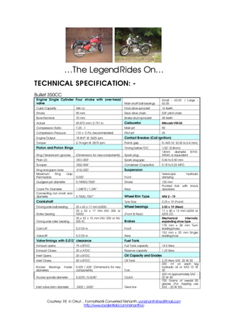
  • 1. …The Legend Rides On… TECHNICAL SPECIFICATION: - Bullet 350CC Engine Single Cylinder Four stroke with over-head Small - 63.03 / Large - valve Main shaft ball bearings 62.05 Cubic Capacity 346 cc Final drive sprocket 16 teeth Stroke 90 mm Rear drive chain 5/8quot; pitch chain Bore-Nominal 70 mm Brake drum sprocket 38 teeth Actual 69.875 mm / 2.751 in. Carburetor Mikcarb-VM-24 Compression Ratio 7.25 : 1 Main jet 90 Compression Pressure 110 +- 5 Psi (recommended) Pilot jet 25 Engine Output 18 BHP @ 5625 rpm Contact Breaker (Coil ignition) Torque 2.74 kgm @ 2875 rpm Points gap 0.14/0.16quot; (0.35 to 0.4 mm) Piston and Piston Rings Timing before TDC 1/32quot; (0.8mm) 14mm diameter B7HS Ring Clearance in grooves (Dimensions for new components) Spark plug (NGK) or equivalent Plain (2) .001/.003quot; Spark plug gap 0.46 to 0.50 mm Scraper .002/.004quot; Condenser (Capacitor) 0.18 to 0.25 MFD Ring end gap in bore .015/.020quot; Suspension Maximum Ring Gap Telescopic hydraulic Permissible 0.030quot; Front damping Gudgeon pin diameter 0.7498/0.7500quot; Stroke 155 mm Pivoted fork with shock Crank Pin Diameter 1.24875 / 1.249 quot; Rear absorbers Connecting rod small end diameter 0.7505/.7507quot; Wheel Rim Type WM 2 - 19 Crankshaft Tyre Size 3.25 x 19 (Front) Driving side ball bearing 25 x 62 x 17 mm (6305) Wheel bearings 3.50 x 19 (Rear) 25 x 62 x 17 mm (NU 305 or 17 x 40 x 12 mm (6203 or Roller bearing N305) (Front & Rear) 6203 ZZ) 25 x 52 x 15 mm (NU 205 or NU Mechanical internally Timing side roller bearing 205 R) Brakes expanding shoe type 178 mm x 38 mm Twin Cam Lift 0.3125 in Front leading shoes 153 mm x 25 mm Single Valve lift 0.3125 in Rear leading shoe Valve timings with 0.012quot; clearance Fuel Tank Exhaust opens 75 o BTDC Full Tank capacity 14.5 liters Exhaust Closes 35 o ATDC Reserve capacity 1.25 liters Inlet Opens 30 o BTDC Oil Capacity and Grades Inlet Closes 60 o BTDC Oil Tank 2.25 liters SAE 20 W 50 200 ml on each leg Rocker Bearings Inside 0.625 / .626quot; (Dimensions for new hydraulic oil or SAE- 10 W diameters components) Fork 30 420 ml approximately SAE - Rocker spindle diameter 0.6235 / 0.6240quot; Clutch 20 W 40 700 Grams of veedol 00 grease (For topping use Inlet valve stem diameter .3425 / .3430quot; Gear box SAE - 20 W 50) Courtesy: RE in Orkut… Formatted & Converted: Nishanth, vonishanth@rediffmail.com http://www.royalenfield.com/nishanthvo
  • 2. Exhaust valve stem diameter .3405 / .3410 Dimensions Valve guide internal diameter .3437/.3447quot; Weight (Dry) 163 kg Valve Guide External Diameter .6270/.6275quot; Pay load (Max) 172 kg Tappet Guide internal diameter .3752/.3760quot; Ground Clearance 14 cm (140 mm) Tappet guide external diameter .7505/.7510quot; Overall length 212 cm (2120 mm) Dry sump, Oil tank integral with Lubrication the crank case Overall width 75 cm (750 mm) Clutch Wet, multiple, oil immersed Saddle height 85 cm (850 mm) Engine sprocket 25 teeth Wheel base 137 cm (1370 mm) Clutch sprocket 56 teeth Electricals Primary Drive Chain 3/8quot; pitch Duplex Chain System 12 V DC Gear Box Overall Gear Ratios 5.32,7.26,9.80 & 14.80 Bullet 500CC Engine Single Cylinder Four stroke with over-head Small - 63.03/ Large - valve Main shaft ball bearings 62.05 Cubic Capacity 499 cc Final drive sprocket 17 teeth Stroke 90 mm Rear drive chain 5/8quot; pitch chain Bore-Nominal 84 mm Brake drum sprocket 38 teeth Actual 83.96 mm / 83.97 mm. Carburetor Mikcarb-VM-28 Compression Ratio 6.5 : 1 Main jet 110 Compression Pressure 110 +- 5 Psi (recommended) Pilot jet 25 Engine Output 22 BHP @ 5400 rpm Contact Breaker (Coil ignition) Torque 3.5 kgm @ 3000 rpm Points gap 0.14/0.16quot; (0.35 to 0.4 mm) Piston and Piston Rings Timing before TDC 1/32quot; (0.8mm) Ring Clearance in grooves (Dimensions for new components) Spark plug NGK BR8 ES or equivalent Plain (2) .001/.003quot; Spark plug gap 0.46 to 0.50 mm Scraper .002/.004quot; Condenser (Capacitor) 0.18 to 0.25 MFD Ring end gap in bore .015/.020quot; Suspension Maximum Ring Gap Telescopic hydraulic Permissible 0.039quot; Front damping Gudgeon pin diameter 0.7498/0.7500quot; Stroke 155 mm Pivoted fork with shock Crank Pin Diameter 1.24875 / 1.249 quot; Rear absorbers Connecting rod small end diameter 0.7505/.7507quot; Wheel Rim Type WM 2 - 19 Crankshaft Tyre Size 3.25 x 19 (Front) Driving side ball bearing 25 x 62 x 17 mm (6305) Wheel bearings 3.50 x 19 (Rear) 25 x 62 x 17 mm (NU 305 or 17 x 40 x 12 mm (6203 or Roller bearing N305) (Front & Rear) 6203 ZZ) 25 x 52 x 15 mm (NU 205 or NU Mechanical internally Timing side roller bearing 205 R) Brakes expanding shoe type 178 mm x 38 mm Twin Cam Lift 0.3125 in Front leading shoes 153 mm x 25 mm Single Valve lift 0.3125 in Rear leading shoe Valve timings with 0.012quot; clearance Fuel Tank Exhaust opens 75 o BTDC Full Tank capacity 14.5 liters Exhaust Closes 35 o ATDC Reserve capacity 1.25 liters Inlet Opens 30 o BTDC Oil Capacity and Grades Inlet Closes 60 o BTDC Oil Tank 2.25 liters SAE 20 W 50 200 ml on each leg Rocker Bearings Inside 0.625 / .626quot; (Dimensions for new hydraulic oil or SAE- 10 W diameters components) Fork 30 420 ml approximately SAE - Rocker spindle diameter 0.6235 / 0.6240quot; Clutch 20 W 40 Courtesy: RE in Orkut… Formatted & Converted: Nishanth, vonishanth@rediffmail.com http://www.royalenfield.com/nishanthvo
  • 3. 700 Grams of veedol 00 grease (For topping use Inlet valve stem diameter .3425 / .3430quot; Gear box SAE - 20 W 50) Exhaust valve stem diameter .3405 / .3410 Dimensions Valve guide internal diameter 3437/.3447quot; Weight (Dry) 168 kg Valve Guide External Diameter .6270/.6275quot; Pay load (Max) 172 kg Tappet Guide internal diameter .3752/.3760quot; Ground Clearance 14 cm (140 mm) Tappet guide external diameter .7505/.7510quot; Overall length 212 cm (2120 mm) Dry sump, Oil tank integral with Lubrication the crank case Overall width 75 cm (750 mm) Clutch Wet, multiple, oil immersed Saddle height 85 cm (850 mm) Engine sprocket 25 teeth Wheel base 137 cm (1370 mm) Clutch sprocket 56 teeth Electricals Primary Drive Chain 3/8quot; pitch Duplex Chain System 12 V DC Gear Box Overall Gear Ratios 5.01,6.83,9.22 & 13.93 DE – CARBONIZING: - After a few thousand kilometers usage the carbon build up in the engine will cause general falling off in power, accompanied by increased fuel consumption and starting trouble. De-carbonizing will normally be necessary every 8000 kilometers. This can be carried out without removing the engine from the frame. The mileage between de-carbonizing will vary from machine to machine depending on the type of usage. A machine used for frequent short journeys will require more attention that one that is used for long distance touring. Removal of the Petrol Tank • Close the petrol tap. Disconnect the petrol hose from petrol tap end. • Remove the two studs which holds the petrol tank to the frame and pull the petrol tank upwards. Removal of the Cylinder head • Remove the engine steady eye bolt. • Disconnect the high tension lead from the spark plug. Remove rocker oil pipe. • Remove the exhaust pipe and silencer. • Remove the air filter by undoing the bolts on the side of the air filter body. • Push the carburetor back clear off the nuts after removing the fixing nuts. • Remove the rocker box covers. • Remove the de-compressor cable from the lever end of the handlebar (LH side). • Remove the rocker arms and bearings completely after removing four 3/16quot; nuts on each. Lift out the push rods both inlet and exhaust. • Remove the six cylinder head nuts and washers • Lift the cylinder head off the barrel, tapping it gently beneath the exhaust and inlet ports with a wooden mallet. Do not tap the fins. Removal of Cylinder and Piston Courtesy: RE in Orkut… Formatted & Converted: Nishanth, vonishanth@rediffmail.com http://www.royalenfield.com/nishanthvo
  • 4. Slacken the two clamp nuts on the top of the crankcase neck. Remove the 1/4quot; nut above the tappet chest and lift the barrel. • Remove the circlip retaining the gudgeon pin on the timing side of piston taking care not to drop the circlip into the crank case. • Extract the gudgeon pin using special tool PED 2015 (with adaptor if necessary) so that the piston and the pin can be replaced the same way around, ie. split skirt to the front. Removal of Valves To remove valves from the cylinder head, first lift off the end caps from the valve stems. If these have stuck they can be removed with a screwdriver. Using compressing tool PED 2018 ST compress the valves springs from the valve tip. Slacken back the compressing tools and release the springs. Withdraw the valve and place its springs, top spring collar, bottom collar, the end cap and split conical collars together in order that they may be reassembled with the valve from which they were removed. If the valve will not slide easily through the valve guide, remove any slight burrs on the end of the valve stem with a carborundum stone or by using a fine jeweler's file to remove any sharp edge or burr. If the burrs are not removed and the valve is forced out, the valve guide may be damaged. Decarbonizing the Cylinder head - Combustion Chamber Remove carbon from the valves, ports and combustion chamber by scraping. Take care not to cause any damage to the valve faces or valve seat inserts. Scrape gently to avoid scoring the cylinder head. DO NOT, under any circumstances, use caustic soda or potash for the removal of carbon from aluminium alloy. Remove the piston rings carefully. For cleaning the grooves in the piston, a piece of broken piston ring thrust into a wooden handle and filed to a chisel point can be used. Piston and Rings If the piston rings are in good condition they can be put back, taking care to fit them in their original grooves and the same way up. If the rings show brown or black patches, or if their gaps are more than specified service limits (Page 79), when in position in the barrel, new rings should be fitted. The correct gap for new rings are given in the technical specifications (pages 6 & 8 ) for 350 and 500cc. The gap should be measured in the least worn part of the cylinder, which will be found at the top or bottom of the bore. Courtesy: RE in Orkut… Formatted & Converted: Nishanth, vonishanth@rediffmail.com http://www.royalenfield.com/nishanthvo
  • 5. Only for 350cc The original size of the cylinder bore is 2.751quot; (69.875mm). If the wear at any point in the bore exceeds 0.008quot; the cylinder should be rebored to 0.020quot; and an oversize piston fitted. (It should be rebored to 0.40quot; after a further 0.08quot; wear). Piston sizes available are .020quot; and .040quot; oversize. The original side clearance between the piston rings and grooves is 003quot;. If the grooves show a wear of .005quot; the piston should be replaced. Big end bearing inspection Examine the condition of the big end while the piston is removed. About 0.10quot; - 0.20quot; end float is permissible and it will be possible to rock the connecting rod slightly. The big end has a floating bush with an original clearance of approximately . 003quot; However, if a DEFINIT E up and down play can be felt engine should be stripped further to have the big-end renewed. Valves, Valve Guides and springs Test the valve guides for wear by trying fit of a new valve in them. Both valves should be quite free, but the exhaust valve has more clearance (.002quot;) than inlet valve. To remove the valve guides from the head, two special tools are required which can be easily made. The first is a piece of tube with an internal bore of not less than 7/8quot;. The second is a mandrel about 4quot; long made from 9/16quot; diameter bar with the end turned down to 1/3quot; diameter for a length of 1/2quot;. Support the cylinder head on the tube, which fits over the collar of the valve guide. Using the mandrel, force the guide out of the head with a hand press or by using a hammer. To fit a new guide, support the head at the correct angle and use a hand press and the same mandrel. If a hand press is not available, the guide can be replaced using a hammer and a mandrel, to prevent damage to the guide. Check the length of the valve springs which are originally 2.020quot; and 2.095quot; for the inner and outer springs respectively. If these have reached the specified service limits they should be renewed. Decompressor Courtesy: RE in Orkut… Formatted & Converted: Nishanth, vonishanth@rediffmail.com http://www.royalenfield.com/nishanthvo
  • 6. If the decompressor holds compression and operates freely there is no need to interfere with it except to remove the carbon from the head of the valve. If the valve is leaking, it will be necessary to regrind it on its seat. This can be done without completely dismantling it. Having disconnected the control cable from the handle bar, unscrew the decompressor from the cylinder head. Compress the spring and remove the spring cap. Unscrew the adjusting screw and locknut from the cable block and pull the cable sideways out of the block. Push the spring upwards and pull the cable nipple out of the body. It will now be possible to remove the cable and nipple through the spring, leaving the decompressor body and spring detachedfrom the control cable. The spring and the cap should now be replaced. The valve may be ground in by applying a thin coating of grinding paste on the seat of the valve and twisting to and fro by means of the cable block at its upper end and occasionally lifting the valve from its seat. Do not rotate the valve through a complete revolution before lifting, as this will groove the seat. After grinding, wash the whole assembly thoroughly in petrol, opening and shutting the valve while doing so. Make sure that all traces of grinding paste have been removed. If the paste should get into the cylinder serious damage would be caused. If the valve shows a tendency to stick-up in the body but otherwise is satisfactory, this can be cured by washing in petrol, though in this case it will not be necessary to disconnect the control cable. If the decompressor valve is badly burnt or bent it must be replaced. Re-assembly after Decarbonising Before building up the engine, see that all parts are scrupulously clean and place them on a clean tray, work bench or over a clean sheet of paper. While re-assembling it is advisable to fit a new gasket between the cylinder barrel and the crankcase. Smear clean oil over the piston and space the ring gaps. The second ring is a taper ring and is marked TOP on the upper surface. WARNING : This mark should be on top when fitted. Reversing the ring will result in pumping of oil into the cylinder and consequent smoking. Place the piston over the connecting rod small end ensuring the split skirt is facing the front and insert the gudgeon pin. Secure the gudgeon pin with the circlips. Oil the cylinder bore and gently push barrel over the piston while keeping the rings compressed in their grooves and seat it gently on the barrel gasket. Refit the 1/4quot; nut above the timing chest. When fitting the head again, apply jointing compound sparingly on both sides of the gasket. Replace the six nuts and tighten them progressively and diagonally from one side to the other to prevent distortion. WARNING : Excess compound may block oil-ways. Place the push rods with the adjustable parts downward. The shorter pushrod is the Inlet. Ensure valve stem caps are fixed on the valve stems. Position the rockers and bearings, making sure that the oil feed holes are at the bottom and that the Courtesy: RE in Orkut… Formatted & Converted: Nishanth, vonishanth@rediffmail.com http://www.royalenfield.com/nishanthvo
  • 7. caps and bases are in line when tightened down. Adjust the push rods after ensuring piston is in TDC on compression stroke. The silencer could be cleaned of carbon using a hot caustic soda solution, if necessary. NOTE: The cylinder head and base nuts should be checked again for tightness, after the engine has been run long enough to get thoroughly warm. Tighten clamp nuts on crankcase finally. For torque tightening of cylinder head nuts please refer torque chart on page .100 SERVICE OPERATION – ENGINE ON FRAME: - Removal of the Timing cover First place a tray under the engine to hold the oil which will escape when the cover is removed. Remove the exhaust pipe and silencer. Remove ten screws from the timing cover, taking care not to lose the sealing washers, one for each screw. NOTE: When removing or refitting the timing cover it is important that the engine is gently cranked. This will prevent damage of pump worm or the pump spindle. Draw off the timing cover, tapping lightly if necessary with a wooden mallet. While refitting the timing cover ensure that the joint washer is correctly located over the oil holes, using a little grease (not compound) to hold it in position. Ensure proper functioning of oil pump by checking oil flow at rocker pipe union when the engine is running at slow speed. Slacken the oil pipe banjo union to see the oil flow and clamp it again properly. Wipe off the oil that has oozed out. Courtesy: RE in Orkut… Formatted & Converted: Nishanth, vonishanth@rediffmail.com http://www.royalenfield.com/nishanthvo
  • 8. Cleaning/Replacement of Oil Filter Element - Oil Feed and Return Filters Overhauling of Oil feed and Return Pumps • Remove the timing cover. • Remove the end covers from both pumps. • Remove the pump discs and plungers. • Remove the pump spindle, which can be pulled out only from the front or return pump end. • Check the fit of the plungers in the pump discs, which should be sliding fit and should be able to be moved in and out by hand. Courtesy: RE in Orkut… Formatted & Converted: Nishanth, vonishanth@rediffmail.com http://www.royalenfield.com/nishanthvo
  • 9. When matching a plunger in the pump disc, if it is found to be too tight a fit carefully lap the plunger in the pump disc, using metal polish until it is just free. If the pump disc is not seating properly in the timing cover, or if a new pump disc is fitted, it should be ensured that the pump disc matches properly and has a perfect seating in the timing cover. Lap the discs in the timing cover with fine metal lapping paste or liquid metal polish using special tools PED 2034 ST for feed pump disc and PED 2035 ST for return pump disc until a fine gray surface is obtained on the pump disc face. NOTE : Replacement pump discs have a lip left at the opposite side of the lapped face. The purpose of this is to hold the disc central in the housing during the lapping-in. It should be filed off before the pump is finally assembled. Care should be taken not to damage the lapped face. Wash all components and passages thoroughly with petrol after lapping, to remove all traces of grinding paste. Check the pump disc springs for fatigue by assembling in the timing cover and placing the pump covers in position. The latter should be held 1/8quot; off the timing cover if the springs are correct. The pump spindle should be renewed if excessive wear has taken place on the teeth. Reassemble the oil pumps, replacing the cover gaskets. Before fitting each cover fill the pump chamber with clean oil. Having assembled the pumps, lay the timing cover flat and fill the oil ports using an oil can. Turn the pump spindle with a screwdriver in a clockwise direction and it can then be checked whether the pumps are operating correctly. Before replacing the timing cover on the engine, fill the filter chamber with clean oil and fit the filter element. NOTE : With the engine running, the oil feed to the big end can be checked by partially unscrewing the feed plug in the timing cover between the oil pumps. The oil return can be checked by slackening the rocker pipe banjo bolt on the cylinder head and observing the oil flow. Removal of Pump Worm and Timing Pinion Unscrew the pump worm using the hexagon head behind the worm, with special tool PED 2006. Withdraw the timing pinion using a special tool PED 2013. CAUTION: The worm nut has a left hand thread. When turned clockwise the worm nut can be loosened and when turned anticlockwise the worm nut gets tightened. Valve Timing The cams are integral with the cam pinions. They have internal sintered iron bushes running on fixed spindles on the timing chest. The cams and the timing pinions are provided with timing marks to set proper valve timings. The procedure is detailed below. Bring the piston to the TDC position. Match the exhaust cam (provided with two sets of punch marks) with the timing pinion so that the two punch marks coincide on both. Match the inlet cam to the exhaust cam so that the single punch mark coincides on both. Push the cams home towards the crankcase. Courtesy: RE in Orkut… Formatted & Converted: Nishanth, vonishanth@rediffmail.com http://www.royalenfield.com/nishanthvo
  • 10. Tappet Adjustment - Cold It is very essential to ensure that the valves are closed fully during the closing period of the cam. The tappet clearance should be adjusted properly to achieve this and to cater for a certain amount of thermal expansion of the working components. We recommend 'NIL' clearance of the tappets to be set at cold. Provision for adjustment is given at the bottom end of the push rod which sits over the tappet. Access to this is by removing the tappet cover. Proceed as follows for adjustments. Bring piston to TDC at the end of compression stroke, so that both the valves are at the closed position. This may be ensured by seeing the valve timing marks if the timing cover is open, or through ammeter needle movement, when ignition is switched on. Check the push rods. They must rotate thumb free without any up and down play. In case the push rods do not rotate freely or if up and down play is noticed, the push rods need to be adjusted. Loosen the lock nut in the adjuster, by holding the top nut. Thread in or out the bottom adjuster, till the correct push rod freedom is achieved. Retighten the lock nut after adjustments are complete. The Clutch - 350cc and 500 cc The 350cc clutch has five driven plates and four driving plates, including the friction disc on the sprocket. The 500cc clutch is similar to that of 350cc, except that there are six driven plates and five driving plates. Also the lugs on the clutch sprocket and the splines on clutch center are longer. Removal of the Clutch Remove the L.H. front foot rest, place a tray beneath the primary chain case to collect the oil in the chain case. Remove the central nut in the chain case outer and remove the cover. To remove the clutch unscrew the clutch spring pins. Lift away the spring caps, springs, clutch front plate, clutch pad in main shaft, the assembly of driving and driven clutch plates and the clutch retaining spring. The clutch sprocket can then be withdrawn along with the chain and engine sprockets (see point 10). The clutch center can be removed only after the engine sprocket, primary chain and the clutch sprocket have been removed. To remove the clutch center hold the clutch with a brake bar (Special tool No PED 2025) and remove the center retaining nut and washer with a box spanner. The clutch center can then be withdrawn from the shaft using extractor (Special Tool No. PED 2005). Courtesy: RE in Orkut… Formatted & Converted: Nishanth, vonishanth@rediffmail.com http://www.royalenfield.com/nishanthvo
  • 11. 1. Clutch center and back plate 12. Clutch intermediate plate assembly (flat) 2. Clutch sprocket 56 T & Drum 13. Clutch bonded plate assembly assembly 3.Clutch sprocket drum (N/S) 14. Clutch front plate 4. Clutch sprocket friction disc 15. Clutch spring 5. Clutch sprocket friction disc rivet 16. Clutch Cap 6. Clutch sprocket ball cage (N/S) 17. Clutch spring screw 7. Clutch sprocket ball cage rivets (N/S) 18. Clutch pad 8. Clutch sprocket balls(3/16quot; dia) (N/S) 19. Clutch rod 20. Washer main shaft 9. Clutch retaining spring (spring) 10. Clutch intermediate plate (dished) 21. Nut main shaft (Nyloc) 11. Clutch plate (insert type) Courtesy: RE in Orkut… Formatted & Converted: Nishanth, vonishanth@rediffmail.com http://www.royalenfield.com/nishanthvo
  • 12. 1. Clutch center and back plate 12. Clutch intermediate plate assembly (flat) 2. Clutch sprocket 56 T & Drum 13. Clutch bonded plate assembly assembly 3. Clutch sprocket drum (N/S) 14. Clutch front plate 4. Clutch sprocket friction disc 15. Clutch spring 5. Clutch sprocket friction disc rivet 16. Clutch Cap 6. Clutch sprocket ball cage (N/S) 17. Clutch spring screw 7. Clutch sprocket ball cage rivets (N/S) 18.Clutch pad 8. Clutch sprocket balls(3/16quot; dia) (N/S) 19. Clutch rod 20. Washer main shaft 9. Clutch retaining spring (spring) 10. Clutch intermediate plate (dished) 21. Nut main shaft (Nyloc) 11. Clutch plate (insert type) Removal of Engine and Clutch sprockets Remove the alternator stator by undoing three nuts. The primary chain is endless hence it is necessary to remove both the engine and clutch sprockets simultaneously. Remove the central hexagon nut securing the alternator rotor, which can then be drawn off, taking care not to lose the key. The engine sprocket is mounted on splines and can be removed along with the clutch sprocket using extractor PED 2004 ST. Removal of Final Drive Sprocket Remove the clutch as described above. Remove the primary chain tensioner. Remove the primary chaincase inner by removing three nuts. Straighten the bent tab of the tab washer, which is provided for locking the final drive sprocket nut. Hold the sprocket and remove the nut (right hand thread). The sprocket can then be withdrawn. Re-assembly of the Clutch Plates When re-assembling the clutch plates the following order must be observed. The clutch pad must be fitted into the main drive shaft, plain dished plate (dish projecting outwards). Friction plate with inserts, plain flat plate, friction plate bonded, plain dished plate (dish projecting inwards), friction plate bonded, clutch front plate, 3 springs on the clutch center lugs. In the case of 500cc one more plain flat plate will also have to be fixed after the plate with inserts has been assembled. The other three springs are located by means of bosses on the clutch cap. Tighten the spring pins as far as they will go. If the clutch lifts un evenly it is probably is that one of the springs has taken a set in which case new springs should be fitted. The friction plates with inserts should be renewed if badly worn or when the inserts have become loose in their plate. The bonded friction plates require renewal when worn or charred. ( A light change to blackish color should not be mistaken as charred). Excessive or premature wear of the platesis due to either running the vehicle at half clutch application or depriving clutch plates of oil, with insufficient or no oil in the clutch chain case. Courtesy: RE in Orkut… Formatted & Converted: Nishanth, vonishanth@rediffmail.com http://www.royalenfield.com/nishanthvo
  • 13. Primary Chain Adjustments Access to the primary chain adjuster is gained by removing the primary chain cover, which is held in position by a single nut. Before removing the nut, place a tray under the engine to collect the oil from the chaincase. Beneath the bottom run of the chain is a curved slipper chain tensioner pad on which the chain rests. This can be raised or lowered by turning the adjusting screw below the chain tensioner pad after having first slackened the locknut. The chain should be adjusted so that there is 1/4quot; up and down movement at the center of the top run of the chain. Remember to check the chain. Remember to check the chain tension at 3 or 4 places and then adjust accordingly. Ensure that the chain tensioner pad moves freely and the lock nut of the adjuster is retightened after carrying out the adjustments. The chain has to be changed if its length has increased by 3/4quot; more than the length of a new chain. After replacing the chain cover remember to replenish the chaincase with oil (SAE 20) up to the level plug in outer chain case (approx quantity 430 to 450 ml) Adjustment of the Clutch Control It is essential that there should be about 3 to 4mm free movement in the clutch cable to ensure that all the spring pressure is exerted on the plates. There are two points of adjustments on the clutch cable. The first is the midway adjuster at the middle of the cable just above the chain case. The adjustment is made by screwing the adjuster screw in or out of the adjuster body. Tighten the locknut on the screwed collar after adjustment has been made. The other point is at the handlebar end. Loosen the locknut and thread in the adjuster to increase play and vice-versa to reduce play. Tighten lock nut after carrying out adjustment. However, if the adjusters have reached their maximum position, then the adjustment can be carried out in the gearbox outer cover. Before proceeding on the adjustment, turn in both cable adjusters to their fully closed position (fully in position). To make the adjustment, remove the inspection cover, slacken the locknut and turn the central screw in to get the desired free play on the clutch lever at the handle bar end. Tighten. Owing to initial bedding down of the clutch plate inserts, the clutch control may require adjustment after the first few hundred kms with a new machine. This point should therefore be examined soon after delivery and adjustment made if necessary. Initially, excessive play in the cable can be taken up through midway adjuster and the adjuster at the handle bar end. NOTE : The clutch adjuster ball and clutch rod may require cleaning and greasing around 6000 miles / 10000 kms usage. To do this, loosen and carefully remove the clutch adjuster from its position, taking care not to drop it into the gearbox outer cover. Start the engine and tilt the motorcycle towards the gearbox side, so that the clutch rod can be removed. Wash thoroughly, the clutch rod and adjuster and look for chipped or worn clutch rod ends and free rotation of the clutch adjuster ball. Courtesy: RE in Orkut… Formatted & Converted: Nishanth, vonishanth@rediffmail.com http://www.royalenfield.com/nishanthvo
  • 14. Smear multipurpose grease on the clutch rod and carefully reassemble in its location. Adjust the adjuster to ensure free play is maintained on the handle bar end and tighten locknut. Fitting the alternator The alternator consists of two parts, the stator and the rotor. The stator is mounted on to the primary chain case inner by three studs and nuts. The rotor, which contains the permanent magnet, is mounted on the end of the drive shaft and is located by a key and secured by a special nut and spring washer. The designed radial air gap between the rotor and the poles of the stator is 0.25mm (0.010quot;) and care must be taken when refitting to see that it is not less than 0.15mm (0.006quot;) at any point. Fit the rotor first, making sure that it is located concentrically on the end of the drive shaft. Attention must be given to the proper seating of the key. Finally secure the rotor with the appropriate washer and nut. Having fitted the rotor, the stator may then be fitted on to the chain case inner with the coil connections facing outwards. Replace the shake proof washers and the nuts on the studs and tighten gently. Insert six strips (preferably non magnetic material) 0.15mm (0.006quot;) thick and 25.4mm (1quot;) wide. Check whether the strips are free in position. If one or more of the Courtesy: RE in Orkut… Formatted & Converted: Nishanth, vonishanth@rediffmail.com http://www.royalenfield.com/nishanthvo
  • 15. strips are not free, gently tap stator (at the opposite end) to centralize the same such that all the strips become free. Tighten the stator nuts and ensure the strips move freely. Gently crank engine, recheck the strips are free. Repeat this process at 3 or 4 places and then withdraw the strips. Function of Breather The efficient operation of the breather is of paramount importance to the performance of the engine because it acts as a non-return valve between the crankcase and the outside atmosphere, causing a partial vacuum in the crankcase and rocker boxes which prevents the passage of oil into the cylinder. If the breather is not acting efficiently, it may cause pressure in the crankcase instead of partial vacuum, giving rise to smoking or oiling of the plug. Gear Box The gears, ratchet mechanism etc. of the gearbox can also be serviced without dismantling the engine from the frame. Please refer page 33 for dismantling the gearbox. Courtesy: RE in Orkut… Formatted & Converted: Nishanth, vonishanth@rediffmail.com http://www.royalenfield.com/nishanthvo
  • 16. REMOVAL OF ENGINE FROM THE FRAME: - Removal of the Engine from the Frame Disconnect alternator leads. viii. Remove the rear chain. ii. Disconnect the spark plug cap, suppressor cap. ix. Remove the footrest (L.H.). iii. Turn off petrol tap and disconnect the fuel pipe. xi. Support the engine on a suitable box or wood block. iv. Remove carburettor assy. along with throttle cable. xii. Remove the center stand and the stand stop. xiii. Remove the front engine plates and the small bolt fixing v. Remove the air filter assy. the stand spring bracket and fix rear mudguard. xiv. Remove the stud securing the rear engine plate to the vi. Remove the exhaust pipe and silencer. frame. vii. Disconnect the engine steady bolt. xv. Slide out the engine. Removal of the Gearbox Remove the primary chain case outer, clutch assembly, stator and rotor, engine sprocket and clutch sprocket. Remove the clutch centre and chain case inner. Remove four 3/8quot; nuts and the gearbox can then be withdrawn from the engine. Dismantling the Crankcase Drain the oil tank by removing the feed and return filter assembly plugs located in the crankcase bottom. Having removed the engine from the frame dismantle the cylinder head, barrel, piston, timing gear etc., as described in the chapter quot;Decarbonisingquot;. Remove the nuts on the driving side of the engine from four fixed studs at the rear of the crankcase. Remove six studs passing through the crankcase by undoing nuts. The two halves of the crankcase can then be separated. The driving side outer race of bearings will remain in the driving side half of the crankcase. The driving side bearing inner race and the inner distance piece will remain on the engine shaft. ( Crankshaft) The flywheel assembly may be removed from the driving side of the crankcase. Removal and Reassembly of main bearings Clean the crankcase thoroughly as any trace of oil in the crankcase will burn and discolor the bearing race while heating the crankcase. Heat the crankcase in an oven or apply the naked flame of a blow lamp on the circumferential area of the bearing boss and not directly on the bearing race. When the crankcase gets heated up fairly, about 110º-120ºC, tap the crankcase on a wooden block (with the bearing race facing downwards) gently so that it will drop down due to the expansion of the bearing boss. Remove the circlip from the driving side crankcase and reheat to remove the ball bearing. Inspect the bearings before assembly. The bearing should spin smoothly. Rotated dry, it may appear to be slightly noisy but there should be no signs of corrosion, nor must there be any appreciable radial slackness. The outer race of the roller bearing must be preferably smooth and bright with no evidence of crack or pitting. The individual rollers must show no signs of wear and should rotate smoothly in the cage. It is recommended to replace with new bearings once they are removed from the crankcase. Reheat the crankcases to reassemble the bearings in the crankcase. Assemble the ball bearings in the D/S crankcase after fitting the circlip. Locate the other circlip, distance tubes outer and inner and then assemble the roller bearing outer race. Ensure that the bearings are seated properly in the crankcase and the outer roller race is flush with the crankcase. Courtesy: RE in Orkut… Formatted & Converted: Nishanth, vonishanth@rediffmail.com http://www.royalenfield.com/nishanthvo
  • 17. Replacement of the Cam Idler Spindles When wear is noticed or step formation seen on the spindle, it should be replaced. To remove the cam spindle, heat the crankcase and tap the spindles out from inside. To remove the idler pinion spindles, heat the crankcases as before, hold the spindles in a vice and tap the crankcase lightly with a nylon/wooden hammer. To replace the cam spindles, locate the spindles in respective holes in the timing side crankcase and drive the spindles in home with a small hammer (1/2 lb.) and a drift. Make sure that the spindles are upright and parallel to each other. Connecting Rod Wear in the hardened steel big end bush will be shown by a formation of a ridge round the centre of the bearing surface corresponding with the oil groove in the white metal floating bush. If this wear is excessive, the connecting rod should be replaced. Excessive wear on the small end of the connecting rod can be easily seen. The Gudgeon Pin will show a rocking motion if wear is excessive. The flywheel assembly consists of the crankshaft and the connecting rod. Courtesy: RE in Orkut… Formatted & Converted: Nishanth, vonishanth@rediffmail.com http://www.royalenfield.com/nishanthvo
  • 18. To dismantle the crankshaft remove the set screws securing the crankpin nuts. Holding the crankshaft in a special jig (PED 2037) remove the crankpin nuts. Using PED 2037 with a pair of steel bars (about 1quot; x 3/8quot; x 9quot; long) placed across between the flywheel disc, press out the crankpin using a hand press. The connecting rod can then be removed along with floating bush. Turn the crankshaft over in the jig and repeat with other side if necessary. To remove the timing shaft, remove the set screw from the shaft nut and unscrew the nut. Drive the shaft out with a hammer and drift. To replace the timing side shaft, reverse the above process, making sure that the key is a good fit and that the nut is tightened securely by means of a box spanner with a 12quot; tommy bar. The driving shaft has no nut but is secured by tightening the sprocket nut after the assembly of the engine. It should be pressed in with a hand press or a hammer and drift. If the latter is used, care must be taken not to damage the centre. It has a collar which butts against the flywheel disc. To reassemble the crankshaft, press the crankpin into the timing side flywheel, making sure that the oil hole is in the correct position and the thrust washer is facing the right way, i.e. with Chamfer away from the flywheel. Test the oil passages using an oil can to make sure that they are clear. Assemble the floating bush over the crankpin. Assemble the connecting rod over the floating bush and smear with engine oil. Place the other thrust washer over the crankpin, also with the Chamfer away from the flywheel. Use a brass drift and hammer for pressing the D/S flywheel. Locate the flywheel in the assembly jig, to ensure that the flywheels and shafts are in line, and replace the nuts. Tighten securely and refit the set screws. Test the oil passages again to ensure that they are clear. If the same crankpin has been put back, it will be necessary to drill out the old grub screw in order to clean the oil passages after which a new grub screw must be fitted. Mount the crankshaft between the centers of a lathe or on a pair of vee block and true up to 0.001quot; on either side of the shafts. If the readings for the two shafts are high on opposite sides, the error can be corrected by gently tapping either or both of the flywheels. If the readings are high on the same side of the two shafts, it is probably due to dirt or foreign matter in the joints and the crankshaft should be dismantled again, carefully examined and reassembled. Courtesy: RE in Orkut… Formatted & Converted: Nishanth, vonishanth@rediffmail.com http://www.royalenfield.com/nishanthvo
  • 19. RE- assembly of crankcase Replace the bearings, etc., in the crankcase halves after heating the crankcase as described earlier. (Refer page 29) Fit the inner distance piece in the driving side crankcase. Fit the thrust washer on the drive shaft. Fit the bearing inner race on the drive shaft. Assemble the flywheel into the bearing. If necessary use the sprocket nut with a suitable spacer to draw the driving shaft through the inner race of the ball bearing. Make sure that the crankcase face is clean and apply jointing compound to it and fix the crankcase gasket in position. Put the thrust washer on the timing side shaft and press the bearing inner race. Place the timing side crankcase in position over the flywheel and gently tap with wooden mallet. Bolt the two halves of the crankcase together making sure that the joint matches correctly so that the cylinder base is flat. Rotate the drive shaft by hand and check for free rotation to ensure correctness in assembly and press the oilseal on to the drive side of the crankcase from outside, ensuring proper seating. For 500cc Press the oil seal onto the timing side of the crankcase and ensure proper seating. Dismantling the Gearbox Courtesy: RE in Orkut… Formatted & Converted: Nishanth, vonishanth@rediffmail.com http://www.royalenfield.com/nishanthvo
  • 20. The gearbox can be completely dismantled with the engine in the frame except for the removal of the inside operator and the bearings in the gearbox case. Remove the kickstarter crank, the gear change lever and the neutral finder. Remove the top and bottom small inspection covers and disconnect the clutch cable, after loosening clutch adjuster. Remove four screws and the gearbox outer cover can then be detached. Remove the foot control plate assembly and foot control by taking off the two nuts securing it. Remove the mainshaft bearing cover which is attachedby two screws. CAUTION: Hold the kickstarter return spring eyelet by means of a long screwdriver to prevent it from rebounding (and causing damage) while the mainshaft bearing cover screw is removed. The mainshaft can be drawn straight out. If the clutch has been removed which, however, should be done before taking off the gear box inner cover, the top gear pinion and dog will come away with the mainshaft. GEAR BOX: - Dismantling the Gearbox The gearbox can be completely dismantled with the engine in the frame except for the removal of the inside operator and the bearings in the gearbox case. Remove the kickstarter crank, the gear change lever and the neutral finder. Remove the top and bottom small inspection covers and disconnect the clutch cable, after loosening clutch adjuster. Remove four screws and the gearbox outer cover can then be detached. Remove the foot control plate assembly and foot control by taking off the two nuts securing it. Remove the mainshaft bearing cover which is attachedby two screws. CAUTION: Hold the kickstarter return spring eyelet by means of a long screwdriver to prevent it from rebounding (and causing damage) while the mainshaft bearing cover screw is removed. The mainshaft can be drawn straight out. If the clutch has been removed which, however, should be done before taking off the gear box inner cover, the top gear pinion and dog will come away with the mainshaft. Removal of the Ball Bearings. The main shaft ball bearings can be removed by using a stepped drift of 0.437quot;(11mm) & 1.171quot;(29.77mm) in diameter for the bearing in the case and 0.812quot;(20.64 mm) & 0.515quot; (13.1 mm) in diameter for the bearing in the cover. When refitting the bearing stepped drifts of 2.31quot; (58.7 mm) & 1.171quot; (29.7 mm) diameter and 1quot; (25.4 mm) in diameter, must be used for bearings in the case and cover respectively. Gear Change Mechanism If the two pins securing the gear change ratchet mechanism are slackened, the adjuster plate can be set in the desired position. In this position the movement of the gear lever, necessary to engage the ratchet teeth, will be approximately the same in each direction. Courtesy: RE in Orkut… Formatted & Converted: Nishanth, vonishanth@rediffmail.com http://www.royalenfield.com/nishanthvo
  • 21. If the plate is incorrectly adjusted, it may be found that, after moving top to third or from bottom to second gear, the outer ratchets will not engage the teeth on the inner ratchets correctly. When fitting new parts, if it is found that the gears do not engage properly, ascertain whether a little more movement is required or whether there is too much movement so that the gear slips right through second or third gear into neutral. If more movement is required, even after adjusting the adjuster plate then this can be obtained by filing the foot control stop plate very slightly at the points of contact with the pegs on the ratchet ring. If too much movement is already present, a new foot control stop plate giving less movement must be fitted. Gear box with Continental controls. The procedure for dismantling the gearbox with Continental controls is the same as described earlier. While dismantling the gear change mechanism care should be taken to disconnect the foot control lever from the gear shift shaft after loosening the hex bolt. The circlip provided on the gear shift shaft should also be removed prior to removing the inner cover. Grease nipples are provided on the shift shaft and gear lever on the left side of the motorcycle for periodical greasing to ensure smooth operation of shift shaft and gear lever. If excessive gear lever travel is noticed and gear engagement becomes difficult, the plastic bushes provided at the gear linkages are worn out and will have to be replaced with new bushes to reduce play in the linkages. Courtesy: RE in Orkut… Formatted & Converted: Nishanth, vonishanth@rediffmail.com http://www.royalenfield.com/nishanthvo
  • 22. 1. Gear box case with bush 36. Plunger spring 71. Clutch lever 2. Gear operator pin 37. Stop plate bolt 72. Clutch lever grease nipple 3. Bush gear operator pin 38. Stop plate 73. Clutch lever bearing cap Courtesy: RE in Orkut… Formatted & Converted: Nishanth, vonishanth@rediffmail.com http://www.royalenfield.com/nishanthvo
  • 23. 74. Clutch lever bearing block pin 4. Drive sprocket (16-T) 39. Washer oil level plug (1/4quot; x 3/16quot;) 75. Clutch lever adjuster with screw 5. Lock washer (D/sprocket) 40. Oil level plug & ball 6. Lock nut felt washer 41. Washer oil filler & drain plug 76. Nut clutch lever adjuster 7. Lock nut (D/sprocket) 42. Oil filler & drain 77. Neutral lever eccentric bush 8. Drive sprocket distance piece 43. End cover with bush 78. Neutral lever stop pin 79. Clutch adjustment inspection 9. Oil seal 44. Bush foot control operator shaft cap 10. Main shaft ball bearing (Large) 45. Washer gear box case joint 80. Inspection pin short 11. Main shaft low gear pinion (25T) 46. Foot operator shaft with lever 81. Neutral lever 12. Main shaft sleeve 47. Gear box cover bolt 82. Cap pin (long) 13. Sliding gear (21T & 18T) 48. Gear box cover screw 83. Gear indicator 14. Main shaft 49. Main shaft ball baring (small) 84. Washer for neutral lever spring 15. High gear pinion dog 50. Oil thrower (outer) main shaft 85. Neutral lever spring 51. Main shaft nut (LH thread) (F/s 16. High gear pinion (15T) end) 86. Spring cap 17. Oil thrower (inner) 52. Ball bearing cap 87. Neutral lever securing pin 18. F/s spindle distance washer 53. K/s return spring 88. Foot change lever 19. Lay shaft high gear & K/s wheel (25T) 54. Cap pin (Long) 89. Pinch bolt & nut 20. Third gear pinion (22T) 55. Cap pin (Short) 90. Foot change lever rubber 21. Second gear pinion (19T) 56. F/c lever return spring 91. Bolt kick starter crank 22. Layshaft 57. Adjuster plate 92. Kick starter crank 23. Low gear pinion (15T) 58. Spring stop 93. Nut kick starter crank bolt 24. Splined bush 59. F/c ratchet spring 94. Rubber kick starter crank 25. Bush (case end) 60. F/c plate spring stop 95. Kick starter pedal pall 26. Gear operator fork 61. Ratchet operating pin 96. Kick starter pedal 27. Nut gear operator (inside) 62. F/c plate 97. Kick starter pedal pivot pin 28. Washer gear operator selector 63. Ratchet (outer) 98. Kick starter pedal spring 29. Gear operator selector assembly 64. F/c plate pin bush 99. Drive sprocket (17T) for 500cc 30. Gear operator (inside) 65. F/c adjuster plate pin 31. F/s spindle quot;Oquot; ring 66. F/c Ratchet (inner) 32. F/s spindle with bush 67. F/c stop plate & spring retainer 33. Layshaft bush 68. Nut (foot control adjuster plate) 34. Foot starter pawl 69. F/c lever short (inside) 70. F/c cover c/w Clutch lever, 35. Plunger bearing cap & pins Note : F/s means Foot Starter, F/c means Foot Control Adjustment of the Neutral Finder The neutral finder is adjusted by means of an eccentric stopper secured to the front of the gearbox cover by a bolt which limits the travel of the operating pedal. Slacken the bolt and turn the eccentric stopper until the correct movement of the pedal is obtained. Courtesy: RE in Orkut… Formatted & Converted: Nishanth, vonishanth@rediffmail.com http://www.royalenfield.com/nishanthvo
  • 24. Lubrication of the Gearbox Current machines have the gearbox filler plug at the top of the box and a level plug at the rear. Remove both plugs and fill, with the machine on level ground until the oil commences to flow from the level plug. Check the level every 800 to 1600 km when the gearbox is warm. For initial filling up of gearbox VEEDOL 'OO' grease is recommended. During routine maintenance, topping up may be done with SAE 50 oil. The capacity is 700 grams (approx.) of 'OO' grease mixed with SAE 50 grade oil to a thick consistency. L U B RICATION: - Lubrication system is by Dry Sump and effected by an automatic and positive double action oil pumps. The oil tank is integral with the crankcase, for ensuring the full rate of oil circulation immediately when the engine is started and for rapid heating of the oil in cold weather. The capacity of the oil sump is 2.25 Ltrs. (SAE 50 grade). There are two piston type oil pumps running at 1/12 of engine speed positively driven by the worm gear on the timing shaft. The feed pump is at the rear of the timing cover (Left side when viewed from the front) and pumps oil from the oil tank, through the oil filter to the big end through the timing shaft. After lubrication of the big end bearings, the oil splashes and lubricates the cylinder barrel walls and drains to the bottom of thecrankcase. The return pump (front sied of the timing cover) draws the oil from the crankcase through the drilled passaage and passes through the rocker oil pipe and lubricates the rocker bearings and valve spring mechanism and flows down through the push rod tunnels into the timing cover chest. From here, the drained oil is pumped back to the oil tank through a hole (drilled in the RH crankcase) by the two idler pinions. The return pump has a capacity of approximately double that of the feed pump, which ensures that oil does not accumulate in the crankcase. If allowed to accumulate it will lead to smoke – oil splash through breather pipe and starvation of oil to rocker arm bearings. Both pumps are double acting, but two sides of feed pump are inter-connected, thereby giving an augmented and even supply to the big end. Return pump is also inter-connected for effective scavenging from crankcase. Gauze strainers are provided for both feed and return filters from the crankcase to ensure oil is free from dirt and sludge. Oil Filter: The oil filter has a special and important feature in design. In the case of clogged filter or should it be neglected the oil pressure will lift the spring and cap off of its seat, thereby automatically by-passing the filter so that the big end bearings will not be deprived of lubrication, even though the oil may be dirty. Courtesy: RE in Orkut… Formatted & Converted: Nishanth, vonishanth@rediffmail.com http://www.royalenfield.com/nishanthvo
  • 25. FE ED PUMP PORTS IN THE TIMING COVER Y – Suction from Oil tank X – Delivery to big end Position 1: The plunger A is drawn out of the feed pump disc C, by the peg B in the spindle D, due to its rotation. The suction port T in the pump disc aligns with the suction port Y in the timing cover and oil from the tank is drawn into the pump disc as the plunger is drawn out Simultaneously, the through hole W in the disc registers with the delivery port in the timing cover. The outward movement of the plunger forces the accumulated oil in the annular space in the timing cover to be delivered to the big end bearings through the oil filter element. FE ED PUMP PORTS IN FEED PUMP DISC T – Suction port R – Delivery port W, Z – Through holes Position 2 : As the pump spindle rotates further the plunger A is pushed into the pump disc C. The delivery port R in the pump disc registers with the delivery port X in the timing cover. The oil in the pump disc is forced out through these ports, by the plunger for supply to the oil filter element and to the big ends. Simultaneously the through hole Z, in the pump disc registers with the suction port Y in the timing cover and draws oil from the tank, into the annular space in the timing cover, due to inward movement of the plunger into the disc. Courtesy: RE in Orkut… Formatted & Converted: Nishanth, vonishanth@rediffmail.com http://www.royalenfield.com/nishanthvo
  • 26. RE TU R N PUMP PORTS IN THE TIMING COVER Y' - Suction from Crankcase X' - Delivery to Rockery Position 1:- The plunger A' is drawn out of the return pump disc C' by the peg B on the spindle D, due to its rotation. The suction port T' in the pump disc registers with the suction port Y in the timing cover and oil from the crank case is drawn into the pump disc as the plunger is drawn out. Simultaneously, the through hole W' in the disc registers with the delivery port X in the timing cover. The movement of the plunger forces the accumulated oil in the annular space in the timing cover to be delivered to the cylinder head. RE TU R N PUMP PORTS IN THE RETU RN PUMP DISC T' - Suction Port R' - Delivery Port W', Z' - Through holes Position 2 :- As the pump spindle rotates further the plunger A' is pushed into the pump disc C'. The delivery port R' in the pump disc registers with the delivery port X' in the timing cover. The oil in the pump disc is forced out through these ports, by the plunger, for supply to the cylinder head. Simultaneously, the through hole Z' in the pump disc registers with the suction port Y' in the timing cover and draws oil from the crank case chamber into the annular space in the timing cover due to inward movement of the plunger into the disc. Description of Frame The frame is built of special cold drawn welded steel tubing incorporating reinforcements wherever necessary, for extra strength. Courtesy: RE in Orkut… Formatted & Converted: Nishanth, vonishanth@rediffmail.com http://www.royalenfield.com/nishanthvo
  • 27. The swinging arm unit forms the chainstay and is fitted with rubber bonded silent-bloc bushes. The swinging arm unit is secured to the main frame by a long bolt passing through the pivot lugs. Removal of Rear Spring Box Unit / Servicing Rear Spring Box Remove the top pivot pin nut, drive out the pivot pin, then hinge the suspension unit back on the lower pivot pin. After removing the lower nut, the unit may be pushed off the pivot pin welded to the fork end. It is a sealed unit and the internal mechanism cannot be serviced. Outer dust cover can be removed using special tool PED-2039 for cleaning coil spring. Removal of Swinging Arm Chain Stay Remove the rear wheel, chain, rear sprocket and brake cover plate assembly from the swinging arm chain stay. Remove one of the pivot nuts and pull the pivot pin from the other end. The chainstay can then be pulled out of the frame. The life of the rubber bonded silent-bloc bushes is very high. But if it is necessary to replace the bushes, the inner sleeves will have to be pressed out first on a press. The rubber can than be taken away from the outer sleeves by pliers. The outer sleeves can be driven out by means of a hammer and a suitable drift. Replace the rubber bonded bushes in the swinging arm, using a suitable drift, press one bush from one end of the pivot bearing tube under a press, until the metal outer sleeve is flush with the end face of the pivot bearing tube. While pressing, it must be ensured that pressure is exerted only on the outer sleeve and not on the inner sleeve of the bush, as axial pressure on the inner sleeve would destroy the bonding of the rubber to the metal sleeves. Similarly press the second bush from the other side of the pivot bearing tube until the metal outer sleeve is flush with its end face. While assembling the swinging arm fitted with rubber bonded silent-bloc bushes to the frame, the pivot nuts should be fully tightened only with the swinging arm positioned in the mid-stroke of the spring boxes, i.e., when the centre distance between the spring box top mounting hole in the frame and the bottom mounting pin on the swinging arm is 9.75quot;. This is recommended so that the rubber bush will be subjected to minimum angular movement in either direction from the mid stroke. Courtesy: RE in Orkut… Formatted & Converted: Nishanth, vonishanth@rediffmail.com http://www.royalenfield.com/nishanthvo
  • 28. Centre Stand To remove the centre stand take out the split pins & washers from both the ends of the stand spindle. Drift out the spindle and withdraw the stand complete after disconnecting both the ends of the stand springs. Courtesy: RE in Orkut… Formatted & Converted: Nishanth, vonishanth@rediffmail.com http://www.royalenfield.com/nishanthvo
  • 29. FRONT FORK: - Description The telescopic fork consists of two legs each of which comprises a main tube of alloy steel tubing which is screwed into the casquette fork head at the upper end and securely clamped to the fork crown. Fitted over the lower end of the main tube is the bottom tube made of high strength aluminum alloy with an integral lug which carries the wheel spindle. Fitted on the lower end of the main tube is a steel bush which is a close fit in the bore of the bottom tube. The upper end of the bottom tube carries a cast iron bush which is a close fit over the outside diameter of the main tube. These bushes are not fitted to the latest Front fork Assemblies. The bush is secured to the bottom tube by means of a threaded housing which contains two oil seals. A stud known as the 'Spring Stud' is fitted in the lower end of the bottom tube and a valve port is secured to the lower end of the main tube. As the fork operates, oil is forced between the spring stud and the bore of the valve port forming a hydraulic damping system. A compression spring is fitted inside the main tube between the upper end of the main tube. The lower end of the main tube and the upper end of the bottom tube are protected by a cover secured to the fork crown. Operation of the Fork The fork provides a range of movement of 150mm/ 6quot; from the fully extended to the fully compressed position. The movement is controlled by the compression spring and by the hydraulic damping system. The hydraulic damping is light on the bump stroke and heavier on the rebound stroke, thus damping out any tendency to pitching or oscillation without interfering unduly with the free movement of the fork when the wheel encounters an obstacle or pot hole. The fork is filled with a light oil (S.A.E 30) to a point above the lower end of the spring so that the damper chamber 'B' is always kept full of oil. Upward movement of the wheel spindle forces oil from the lower chamber 'A' through the annular space between the spring stud and the bore of the main tube valve port into the damper chamber 'B'. During this stroke the pressure on the underside of the valve plate causes it to lift so that oil can also pass from 'A' to 'B' through the eight holes in the valve body. Since, however, the diameter of chamber 'B' is less than that of chamber 'A' there is no room in 'B' to receive all the oil which must be displaced from 'A' as the fork operates. The surplus oil passes through the cross hole in the spring stud and up the centre hole in the stud, spilling out through the nut which secures the upper end of the spring stud to the lower end of the fork spring. On the stroke, the oil in the damper rebound chamber 'B' is forced through the annular space between the spring stud and the bore of the main tube valve port. During this stroke pressure in chamber 'B' closes the two disc valves at the upper and lower ends of the chamber so that the only path through which the oil can escape is the annular space between the spring stud and the port. Damping on the rebound stroke is therefore heavier than on the compression stroke. At the extreme end of either pump or rebound stroke a small taper portion on the spring stud enters the bore of the valve port, thus restricting the annular space and increasing the amount of damping . At the extreme end of the bump stroke, the larger diameter taper on the oil control collar enters the main counter bore of the valve port thus forming a hydraulic cushion to prevent metal to metal contact. Courtesy: RE in Orkut… Formatted & Converted: Nishanth, vonishanth@rediffmail.com http://www.royalenfield.com/nishanthvo
  • 30. Dismantling the Fork Place the machine on the centre stand, disconnect the front brake control cable & speedometer connection and remove the front wheel and mudguard complete with stays. Unscrew the bottom spring and the stud nut which will allow oil to run out of the fork down to the level of the cross hole in the spring stud. Now knock the spring stud upwards into the fork with a soft mallet, thus allowing the remainder of the oil to escape. Pull the fork bottom tube down as far as possible, thus exposing the oil seal housing. In the latest version the oil seal housing is eliminated and the oil seals are provided as an integral part of the bottom tubes. Hence by pulling the bottom tube downwards it can be removed from the fork main tubes. [For old type front forks: Unscrew this housing by means of a spanner on the flats with which it is provided. The bottom tube can now be withdrawn completely from the main tube leaving the bottom tube bush, oil seal housing and oil seal in position on the main tube. Now unscrew the main tube valve port using special tool PED 2026.The spring stud and spring can now be withdrawn from the lower end of the main tube. NOTE : In the latest version the oil seal housing and steel bush has been eliminated on introduction of integral oil seals in the bottom tubes. The steel main tube bush can now be tapped off the lower end of the tube, if necessary using the bottom tube bush for this purpose. Before doing this, however, it is advisable to mark the position of the bush with a pencil so as to ensure re- assembling it in the same position on the main tube. The reason for this is that these bushes are ground to size, after fitting on to the tubes, so as to ensure concentricity. After removal of the main tube bush, bottom tube bush and oil seal housing, Courtesy: RE in Orkut… Formatted & Converted: Nishanth, vonishanth@rediffmail.com http://www.royalenfield.com/nishanthvo
  • 31. the main tube can be removed using tool PED 2036ST. Before attempting to loosen the main tubes, ensure that the 2 pinch bolts on the fork crown bottom have been successfully loosened to allow the main tubes to rotate. Spring The free length of the spring is 20 1/2quot;. The spring should be replaced if it has closed by more than 1 inch. Re-assembly When refitting the oil seal, or fitting a new one, great care must be exercised not to damage the synthetic rubber lip which forms the actual seal. NOTE : Only for Old Type Forks): If the oil seal housing has been removed from the upper end of the main tube and is refitted from this end, a special nose piece must be fitted over the threaded end of the tube to prevent damage to the oil seal. The spring stud is a tight fit in the hole at the lower end of the bottom tube. Once the stud has been located in the hole, push the bottom tube up sharply against the spring until two or three threads on the stud project beneath the end of the bottom tube. Now fit the nut and washer and pull the stud into position by tightening the nut. If necessary fit the nut first without the washer until sufficient thread is projecting to enable the washer to be fitted. Removal of complete fork Assembly The fork complete with the front wheel and mudguard can be removed from the machine, if necessary, by adopting the following procedure. The leads to the lighting switch and ammeter should be disconnected at their lower ends or by means of the plug and socket connectors where these are provided. Disconnect the speedometer drive from the speedometer head. Remove the two plug screws and loosen the steering head clip bolt and the fork crown clamp bolts. Unscrew the fork main tubes from the headlamp casing and the steering stem locknut from the top of the steering stem, turning each tube and the nut a turn or two at a time. When the nut has been removed from the steering stem and the main tubes have been completely unscrewed from the headlamp casing, the complete fork and wheel with the steering stem can be removed. Lubrication The lubrication of the fork internal parts is effected by the oil which forms the hydraulic damping medium. All that is necessary is to keep sufficient oil in the fork to ensure that the top end of the bottom spring stud is never uncovered even in the full rebound position. The level of oil in the fork can be gauged by removing the top plug screw and inserting a long rod about 3/8quot; in diameter. If slightly tilted this will wedge against the nut at the upper end of the bottom spring stud. If the oil is above the spring stud, it will leave a trace on the long rod, which can be seen on removal. This trace of oil implies that oil level is correct. If the fork is empty to start with, the quantity required is 200ml in each leg. Recommended grade of oil is hydraulic oil or SAE 10 W 30. SEQUENCE FOR ADJUSTMENT 1. Loosen the Head lamp casing clip bolt by using an Allen Key (size 5mm) 2. Loosen the front fork crown clip bolts (2 Nos.) 3. Then screw down the steering stem lock nut by 1/2 thread to 3/4 thread initially and check the play once again. If necessary further tightening can be done. 4. NOTE : Over tightening of this steering Stem lock nut will result in vehicle drag. Courtesy: RE in Orkut… Formatted & Converted: Nishanth, vonishanth@rediffmail.com http://www.royalenfield.com/nishanthvo
  • 32. Lubrication-Steering Head The steering head races and stand pivot bearing should be well greased on assembly. No nipples are provided for the steering head as experience has shown that the provision of nipples at this point causes trouble through chafing and cutting of control and lighting cables. If the steering head bearings are well packed with grease initially they will last for several years or many thousands of kilometers. WHEEL S : - Removal from Fork To remove the front wheel from the fork place the machine on the centre stand with sufficient packing beneath the stand to lift the front wheel clear off the ground when the vehicle is tilted back. Slacken the brake cable adjustment and disconnect the cable from the handlebar lever and from the operating cam lever on the hub. Disconnect speedometer driving cable. Unscrew the four nuts securing the fork lug caps and allow the wheel to drop forward out of the front fork. Make sure that the machine stands securely on the rear wheel and centre stand. If necessary, place a weight on the dual seat or a strut beneath the front end of engine near frame down tube to ensure this. Dismantling Lock the brake 'on', by applying the front brake and unscrew the cover plate nut. (For front brake with twin leading shoes loosen the lock nuts on the link rod and turn link rod so that both brake shoes become free and are not in contact with the brake drum). The cover plate assembly can then be withdrawn from the brake drum. The brake shoes can be removed after detaching the return springs. Brake linings are supplied in pairs and are of 'Bonded' type hence linings cannot be separated and re-fixed with new linings. To remove the operating cam unscrew the nut, which secures the operating lever to the splines on the cam. A sharp tap on the end of the cam spindle will now free the lever, after which the cam can be withdrawn from its housing. The brake shoe pivot pin can be removed after unscrewing the nut which secures it to the cover plate. To remove the hub spindle and bearings, having first removed the brake cover plate, unscrew the retaining nut by holding the spindle on a bench vice with soft jaws. Remove speedo drive assembly and the felt washer from the other side of the hub. Remove the felt washer and the distance washer from the brake drum side and hit one end of the spindle with a brass or plastic mallet, thus driving it out of the hub, bringing one bearing with it and leaving the other in position in the hub. Drive the bearing off the spindle and insert the latter once more in the hub through the end from which it was removed. Now drive the spindle through the hub, the other way, which will bring out the other bearing. Courtesy: RE in Orkut… Formatted & Converted: Nishanth, vonishanth@rediffmail.com http://www.royalenfield.com/nishanthvo
  • 33. Fitting Limits for Bearings The fit of the bearings in the hub barrel is important. The bearings are locked on the spindle between shoulders and the distance pieces , which in turn are held by the nuts on the spindle. In order to prevent endways pre-loading of the bearings, it is essential that there is a small clearance between the inner edge of the outer race of the bearing and the back of the races in either end of the barrel. To prevent any possibility of sideways movement of the hub barrel on the bearing, it is therefore necessary for the bearings to be a tight fit in the barrel, but this fit must not be so tight as to close down the outer race of the bearing and thus overload the ball race in the bearing. 1. Front Wheel rim (WM 2-19) 14. Front brake shoe c/w lining S/L 2. Front Wheel spokes (outer) 15. Front brake shoe spring (7quot; dia.) 16. Front brake cover plate (7quot; dia.) 3. Front Wheel spoke nipples S/L 17. Front brake show pin (7quot; dia.) 4. Front hub assembly (7quot; dia.) S/L 5. Front hub journal bearing (SKF 6203) 18. Washer front brake shoe pin S/L 6. Front hub spindle 19. Nut front brake shoe pin S/L 20. Front brake operating cam (7quot; 7. Front hub felt retainer dia.) S/L 8. Front hub felt washer (drum side) 21. Nut front hub cover plate 22. Front hub spindle nut (speedo 9. Front hub cover plate distance collar side) 23. Front brake operating cam lever 10. Front hub felt washer (speedo side) (7quot; dia.) (S/L) 11. Front hub felt washer retainer (speedo 24. Washer front brake operating side) cam lever (S/L) 25. Nut front brake operating cam 12. Front hub speedo drive spacing collar lever S/L 13. Speedo drive complete Re-assembly To refit the bearings in the hub, two hollow drifts (Special Tool No. PED 2011) are required. One bearing is first fitted to one end of the spindle by means of the hollow drift. The spindle and bearing are then inserted into one end of the hub barrel, which is then supported on one of the hollow drifts. The other bearing is then inserted over the upper end of the spindle and driven home by means of the second hollow drift either under a press or by means of a hammer, which will thus drive both bearings into position simultaneously. Courtesy: RE in Orkut… Formatted & Converted: Nishanth, vonishanth@rediffmail.com http://www.royalenfield.com/nishanthvo
  • 34. In order to make quite sure that there is clearance between the inner faces of the outer bearing races and the bottom of the recesses in the hub, fit the distance washers, cover plate, dust excluder and the nuts on the spindle. Tightening the nuts should not have any effect on the ease with which the spindle can be rotated. 26. F/B operating lever (short) T/L 34. Front Brake Cover Plate T/L 27. Front brake lever long T/L 35. Front brake shoe pin T/L 28. Link Rod Front Brake T/L 36. Washer Front brake shoe pin T/L 29. L/Rod Trunnion (RH Thread) T/L 37. Nut Front brake shoe pin T/L 30. L/Rod Trunnion Nut (RH) T/L 38. Front brake operating cam 39. Washer front brake operating 31. L/Rod Trunnion (L/H) T/L (NF) cam 32. L/Rod Trunnion Nut (LH) T/L (NF) 40. Nut front brake operating cam 33. Front brake shoes C/W lining T/L If tightening the nuts makes the spindle hard to turn, the bearings are bottoming in the recesses in the hub barrel and the inner races are not resting on the shoulder of the spindle. In this case, the bearing should be removed and a thin packing shim should be fitted between the inner race and the shoulder on the spindle. Assemble the operating cam into cover plate after smearing grease on the pivot pin and the cylindrical bearing surface of the operating cam. Fit the operating lever on its splines in a position to suit the extent of wear on the linings and secure with the nut and washer. Note that the position of the operating lever may have to be corrected when adjusting the brake after refitting the wheel. The range of adjustment can be extended by moving this lever on to a different spline. NOTE : Before replacing the felt washers which form the grease seals, pack all bearings with medium/lime soap or aluminium soap greases or multipurpose grease. The use of H.M.P. greases which have a soda soap base is not recommended, as these tend to be slightly corrosive if any dampness finds its way into the hubs. Make sure the inside of the brake drum is quite free from oil or grease, dampness, etc. When replacing the speedo drive, make sure that the dogs on the speedo drive are correctly engaged with the slots in the end of the hub barrel. Make sure that the speedo drive is correctly positioned, so that the speedo cable would not be too stretched or will not have any sharp bends. Replace the felt washers, distance collars, and brake cover plate and securely tighten the spindle nuts. Removal of wheel - quickly-detachable type The rear wheel is quickly detachable without disturbing the sprocket. Place vehicle on centre stand. Remove the split pin and the castle nut securing the long spindle which is located on the sprocket side. Slide out the long spindle from the wheel and remove both the spacers from the RH side fork end. Tilt the vehicle and slide out the wheel from the chainstay. For assembly reverse the process but take care to engage the cush rubbers properly on the driving lugs. Courtesy: RE in Orkut… Formatted & Converted: Nishanth, vonishanth@rediffmail.com http://www.royalenfield.com/nishanthvo
  • 35. Cush Drive Four rubber blocks are fitted in the pockets of centre hub and four radial vanes are formed on the back of the rear sprocket/brake drum, thus transmitting both driving and braking torque and smoothening out harshness and irregularity in the former. If the cush drive rubbers are worn, and the amount of free movement measured at the tyre exceeds 1/2quot; to 1quot;, the rubbers should be replaced. The condition of the cush drive rubber in the rear wheel can be gauged by placing the machine on the rear stand, applying the rear brake and rotating the rear wheel. The cush rubbers are fixed in the pockets of the centre hub by means of buttons provided in the rubber blocks, thus the rubbers are prevented from falling down when wheel is removed or refitted. Removal and re-assembly of rear wheel sprocket Removal of sprocket is necessary only if replacement of sprocket or attention to brakes is required. Remove the wheel as described above. Remove the brake rod nut and disconnect the brake rod from the operating lever. Be sure to quot;DISCONNECTquot; the stop light switch from the link, otherwise the switch will get damaged. Remove the securing bolts of the chainguard at both front and rear ends and remove the chainguard. Disconnect the chain link. Remove the securing nuts from brake anchor and wheel spindle. Unwrap the chain from the rear sprocket. Slide out the rear sprocket assembly from the chainstay. For re-assembly proceed in the reverse order. Make sure that the inside of the brake drum is quite free from oil, grease, dampness, etc. Ensure the chain lock clip is fitted in the right direction so that the closed end of the clip is towards the direction of motion. The rear chain should be inspected for wear before assembly. It should be renewed when its length has increased by 1-1/8quot; more than a new chain. The rear chain can be adjusted by slackening the wheel spindle nuts and brake anchor shoe pin nut and turning the notched cam plate. Courtesy: RE in Orkut… Formatted & Converted: Nishanth, vonishanth@rediffmail.com http://www.royalenfield.com/nishanthvo
  • 36. 22. Rear brake cover plate distance 1. Rear wheel rim WM 2-19 collar 2. Rear wheel spokes (dust cover side- outer) 23. Rear brake cover plate assembly 24. Rear hub distance collar ( drum 3. Rear wheel spokes (dust cover side-inner) side ) 4. Rear wheel spoke nipples 25. Rear brake shoe pin 5. Centre hub with barrel 26. Nut rear brake shoe pin 27. Washer rear brake shoe pin 6. Rear hub bearing spacer assy. (plain) 7. Rear hub dust cover 28. Shoe pin nut near brake anchor 8. Rear hub dust cover screw 29. Rear brake operating cam 9. Rear hub barrel 'O' ring 30. Rear brake cam bush 31. Rear brake operating cam bush 10. Rear hub arease seal (small) pin (long) 32. Rear brake operating cam bush 11. Rear hub journal bearing pin (short) 33. Rear brake operating cam bush 12. Rear hub grease seal (small) pin locknut 13. Rear hub spindle (long) 34. Rear brake return spring 35. Rear brake operating Cam Lever 14. Rear hub sprocket cush rubber Assy 15. Rear hub sprocket 38T 36. Washer rear brake lever 16. Rear hub spindle (short) 37. Nut rear brake lever 17. Rear hub bearing (large) 38. Rear hub adjuster (RH) 18. Distance collar (dust cover inner side) 39. Rear hub adjuster (LH) 19. Rear hub distance collar (dust cover outer side) 40. Lock nut (Rear hub spindle) 20. Rear brake shoe c/w lining (bonded) 41. Nut rear hub spindle 21. Rear brake shoe spring 42. Rear hub spindle split pin Courtesy: RE in Orkut… Formatted & Converted: Nishanth, vonishanth@rediffmail.com http://www.royalenfield.com/nishanthvo
  • 37. Dismantling the Rear Brake Shoes After separating the cover plate from the sprocket assembly unscrew the brake shoe pivot pin lock nut and the operating lever nut. The assembly of brake shoes, return springs, pivot pin and operating cam can be removed from the cover plate by unscrewing the pivot pin and applying light blows with a hammer and drift on the end of the operating cam. The return spring can then be unhooked from the brake shoes. Brake linings are supplied in pairs and are bonded type hence linings cannot be separated and refitted with new linings. Removal of bearing from center hub and reassembly The bearing from the center hub can be moved by inserting a small rod of 6 mm dia. Insert the rod through the bearing at one end and through the slit provided at the ends of the bearing distance tube. Hit the rod with a small mallet on radially opposite sides of the bearing. The other bearing also can be removed by hitting it from opposite side after the removal of grease seal. To remove the hub spindle (short) and bearings from the brake drum, having already removed the brake cover plate assembly, hit the outer end of the spindle with a brass hammer or mallet, thus driving it out of the bearing. Now the grease seal and the bearing from the brake drum can be removed one after the other. The fit of the bearings in the hub barrel is important as in the case of Front wheel. To fit the bearings in the hub, use the two hollow drifts and proceed as follows. In order to make sure that there is clearance between the inner faces of the bearings and the bottom of the recess, first fit the sealed bearing at the cush drive side of the center hub so that the bearing will sit in the housing flush with the boss face. Then place the distance tube from the other end and press the second bearing and also the grease seal (small). NOTE : Before replacing the bearings in the center hub as well as the sprocket brake drum, pack with medium/heavy lime soap or aluminum soap grease. The use of HMP greases which have soda soap base is not recommended as these tend to be slightly corrosive if any dampness finds its way into the hub. Re-assembly of brake shoes Make sure that the brake shoe pivot pin is really right in the cover plate and smear grease in the grooves of the pivot pin and on the operating face of the cam. Also smear grease on the Courtesy: RE in Orkut… Formatted & Converted: Nishanth, vonishanth@rediffmail.com http://www.royalenfield.com/nishanthvo
  • 38. cylindrical bearing surface of the operating cam, if this has been removed. Fit the operating lever on its splines in a position to suit the extent of wear on the linings and secure with the nut. The range of adjustment can be extended by moving the lever onto a different spline. Note that the bolt holes in the cover plate for locating the rear brake cam bush are slotted, to enable the brake shoe assembly to be centered in the drum. The brake cover plate assembly with the shoes should be fitted over the spindle into the brake drum and the brake applied as hard as possible by means of the operating lever. This will center the shoes in the drum. The brake cover plate assembly should then be removed and the screws should then be tightened fully and secured with the lock nuts. If the shoes are not correctly centered, the brake will be either ineffective or too fierce, depending on whether the trailing or leading shoe first makes contact with the drum. With the brake assembly correctly centered, the screws securing the cam housing correctly tightened, wear on both linings should be approximately equal. Adjustment of Drive Chain Check slackness of the drive chain every 1000 Km and adjust if necessary. The frequency of adjustment depends entirely on the rider habits and usage conditions. If the chain is adjusted too loose or too tight, the chain may either jump off the sprocket or might break, causing serious damage to vehicle/engine parts and may also lead to serious accident. The procedure for adjusting the rear chain is as follows: Place the vehicle on its center stand on a firm flat surface. Unfold and remove the split pin (1) on the castle nut on LH side of rear wheel. Loosen the castle nut (2). Loosen the stub axle nut (3) and rear brake anchor pin nut (4). Move the cam adjusters to the same number of notches on either side of the axle. Rotate the rear wheel and check the chain tension on the top run of the chain. The minimum free play of the chain should be 25 to 30 mm with the vehicle on its center stand. Check the wheel alignment of front and rear wheel, using a straight edge or by means of stretching a rope from the front wheel to rear wheel. Retighten the stub axle nut. Rotate the rear wheel, apply the rear brake hard and hold the rear brake pedal firmly in the depressed position so that the brake assembly is centralized in the brake drum. Retighten the brake anchor pin nut. Release the brake pedal. Ensure that the chain adjuster on the RH side is butting against the peg on the chain stay and is not disturbed from its adjusted position. Retighten the castle nut fully such that the split pin hole is aligned. Locate the split pin in position and bend out the split ends. Check the chain tension again at 3 or 4 places by rotating the wheel and ensure the free play is 25 to 30 mm on the top run. Wheel Alignment Courtesy: RE in Orkut… Formatted & Converted: Nishanth, vonishanth@rediffmail.com http://www.royalenfield.com/nishanthvo