1. Susan Ferdon, EDTECH 552 SP11
Module 5, Assignment 4-2
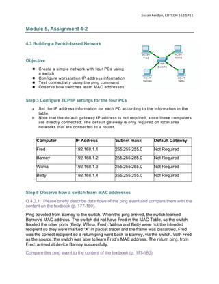
4.3 Building a Switch-based Network
Objective
Create a simple network with four PCs using
a switch
Configure workstation IP address information
Test connectivity using the ping command
Observe how switches learn MAC addresses
Step 3 Configure TCP/IP settings for the four PCs
a. Set the IP address information for each PC according to the information in the
table.
b. Note that the default gateway IP address is not required, since these computers
are directly connected. The default gateway is only required on local area
networks that are connected to a router.
Computer IP Address Subnet mask Default Gateway
Fred 192.168.1.1 255.255.255.0 Not Required
Barney 192.168.1.2 255.255.255.0 Not Required
Wilma 192.168.1.3 255.255.255.0 Not Required
Betty 192.168.1.4 255.255.255.0 Not Required
Step 8 Observe how a switch learn MAC addresses
Q 4.3.1: Please briefly describe data flows of the ping event and compare them with the
content on the textbook (p. 177-180).
Ping traveled from Barney to the switch. When the ping arrived, the switch learned
Barney’s MAC address. The switch did not have Fred in the MAC Table, so the switch
flooded the other ports (Betty, Wilma, Fred). Wilma and Betty were not the intended
recipient so they were marked “X” in packet tracer and the frame was discarded. Fred
was the correct recipient so a return ping went back to Barney, via the switch. With Fred
as the source, the switch was able to learn Fred’s MAC address. The return ping, from
Fred, arrived at device Barney successfully.
Compare this ping event to the content of the textbook (p. 177-180):
2. Susan Ferdon, EDTECH 552 SP11
Both events began with an empty MAC Table.
As mentioned on page 177, if a frame enters the switch and the source MAC
address is not in the MAC address table, the switch creates an entry. This is what
happened when Barney’s ping arrived at the switch – the switch added Barney to
the MAC Table.
In the book, there is no address in the MAC Table, so the switch floods the ports.
The same happened in our example.
In the example on page 178, the next MAC address is added after frame 2. The
same thing happens when Fred pings back – Fred’s MAC address is added to the
Table when it pinged back Barney.
The book discussed Spanning Tree Protocol (STP). There is no evidence of STP
in the packet tracer simulation. All end-devices are operating as expected –
powered on and responding - and there are no loop-backs.
My screen capture video of this process may be viewed at:
http://www.youtube.com/watch?v=m92vQiUD2wM
Step 9 Please save your packet tracer file and submit it with this week’s lab
activities
Lab 4.4 Collision and Broadcast Domains
The purpose of this lab is to observe how several small domains reduce the negative
effects of a large collision domain.
Objective
Use Packet Tracer to observe the function differences between switch and hub
Step1
Download NA01-0815.pkt
(http://edtech2.boisestate.edu/hungj/edtech552/spring2011/lab/lab4/2011/NA01-0815.zip)
Unzip and open it in the packet tracer.
Step 2 Switch to the simulation mode
Step 3 Enable switch MAC address table
Step 4 Enable PDU list window and ARP & ICMP events
Step 5 Send the following simple PDU events
Ping Fred –> Wilma Ping Wilma -> Barney
Ping Wilma -> Barney Ping Betty -> Wilma
Ping Fred -> Barney