
Recomendados
Más contenido relacionado
La actualidad más candente
La actualidad más candente (20)
Destacado
Destacado (20)
Similar a Components operational amplifiers
Similar a Components operational amplifiers (20)
Más de sld1950
Último
Último (20)
Components operational amplifiers
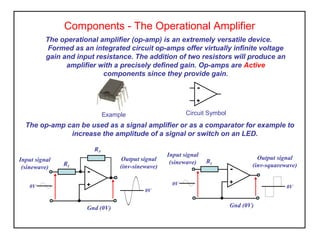
- 1. Components - The Operational Amplifier The operational amplifier (op-amp) is an extremely versatile device. Formed as an integrated circuit op-amps offer virtually infinite voltage gain and input resistance. The addition of two resistors will produce an amplifier with a precisely defined gain. Op-amps are Active components since they provide gain. The op-amp can be used as a signal amplifier or as a comparator for example to increase the amplitude of a signal or switch on an LED. Example Circuit Symbol + - RF Input signal (sinewave) Output signal (inv-sinewave) + - RI Gnd (0V) 0V 0V Input signal (sinewave) Output signal (inv-squarewave) + - RI Gnd (0V) 0V 0V
- 2. Manufactures use an alphanumeric code printed on the device as identification e.g. TL071, TL082, µA741, LM358. It is necessary to refer to manufacturers data sheets to obtain lead information and ratings. Single and dual op-amps are available in 8 pin dual-in-line (DIL) packages and quad versions are available in 16 pin DIL packages. In each case pin 1 is always on the top left. Op-Amp Markings and Packaging non-inverting input 3 TL 07 1 -ve supply 4 7 +ve supply Pin 1 marker 6 Output inverting input 2 1 5 8 Pin layout for typical single op-amp
- 3. Operational Amplifier Connections The op-amp has two inputs and one output, the inverting input produces a 180o phase shift while non-inverting input produces zero phase shift. It is common to operate op-amps using a dual-rail d.c. supply this allows the output voltage to swing symmetrically about 0volt level, usually within 2 volts of the supply rails. Inverting Input Non-Inverting Input + - +ve supply (VCC) Output 72 3 6 4 -ve supply (VDD) VCC (+) VDD (-) Gnd (0v)
- 4. Gain function Closed Loop Uses negative feedback to control the gain and increase frequency response. Some (or all) of the output signal is fed back to the input via a resistor (RF). This mode of operation is used for small signal amplification. Open Loop No feedback is provided in open loop the gain is extremely high but frequency response is very low. This mode of operation is ideal for comparator circuits. Open Loop + - Vo Vi RF + - RI Vo Vi Closed Loop 100 000 VoltageGain 0 10 103 105 106 f (Hz) 10 100 1000 10 000 open loop closed loop
- 5. The Inverting Amplifier The input signal (Vi )is applied to the inverting (-) input via resistor RI. Negative feedback is applied to control the gain via resistor RF. RF + - RI 0V 0V0V Vi Vo Gain = = - Vo Vi RF RI VO = - Vi RF RI The negative sign shows that Vo is negative when Vi is positive, (180° phase shift), or inverting the signal.
- 6. The Non-Inverting Amplifier The input signal (Vi )is applied to the non-inverting (+) input. A portion of the output is fed back to the inverting input via RF and RI to set the gain. The output signal is in-phase (non inverting) with the input signal. Gain = = 1 + Vo Vi RF RI Vo = Vi (1 + RF RI ) RF + - RI 0V 0V0V Vi Vo
- 7. The Summing Amplifier By using multiple inputs the op-amp can provide the sum of ac or dc voltages. The gain function is the sum of the individual gain for each input. These circuits are used as “mixers” for audio signals such as microphones, guitars etc. and can also perform mathematical calculations in analogue computers. RF + - R1 0V V1 Vo R3 R2 V2 V3 Vo = - RF RI (V1 + V2 + V3)
- 8. The Comparator When used in ‘open’ loop mode the op-amp has extremely high gain (typ.100,000) this is ideal if we want to compare a varying voltage with a fixed reference. The output (Vo) can then be used to operate an alarm, pump, lamp, power supply regulation etc. This type of circuit is ideal for the control of a central heating system, the room temperature can be compared with a thermostat setting and then used to switch the pump on or off. + - 0V Vi Vo 0V 0V Vi Vo + + - - - -
- 9. Op-Amp Circuits Assessment 1. An inverting amplifier circuit has a feedback resistor of 100kΩ and an input resistor of 5kΩ. Determine the output voltage if the input is 2mV. 2. A control circuit requires a 6 volt trigger signal to operate a relay. If the sensor output is 100mV determine suitable resistor values for input and feedback. 3. A non-inverting amplifier has a feedback resistor of 50kΩ and an input resistor of 2kΩ. If the input voltage is 500mV determine the output voltage. 4. Explain why the open loop mode of operation is good for the comparator circuit but useless for audio signals.
- 10. Inverting Amplifier (practical activity) This task is to build and test an inverting amplifier using the 741 op-amp and a dual rail power supply. On completing the circuit compare your results with others in the class. You may also wish to investigate further by observing the effect of changing R2 for a value of your choice. circuit diagram The activity also forms part of your achievement criteria. R1 10k VCC +15V R2 100k + - Gnd 0V Vi Vo R3 10k VDD -15V Gnd 0V
- 11. Regulated Power Supply The power supply uses an operational amplifier to provide a stable regulated voltage at its output. It uses negative feedback to control the output voltage. VDC 11.2V ZD1 5.6V + - R1 10k Gnd 0V Unregulated DC Input R2 10k R3 10k Regulated DC Output Gnd 0V VDC 13 - 20V
- 12. Op-amp Comparator (practical activity) This task is to build and test a comparator circuit using the 741 op-amp and a dual rail power supply. You will gain experience in identifying and handling components, planning circuit layout and use of test equipment. circuit diagram The activity also forms part of your achievement criteria. R1 10k VCC +15V + - Gnd 0V Vi Vo VR1 47k VDD -15V