SlideShare una empresa de Scribd logo
1 de 35
DISTILLATION: AN INTRODUCTION
Distillation is defined as:
           A process in which a liquid or vapor mixture of two or more substances is
separated into its component fractions of desired purity, by the application and
removal of heat.


Distillation is based on the fact that the vapor of a boiling mixture will be richer in the
components that have lower boiling points.
 Therefore, when this vapor is cooled and condensed, the condensate will contain more
volatile components. At the same time, the original mixture will contain more of the less
volatile material.
Distillation columns are designed to achieve this separation efficiently.
Although many people have a fair idea what “distillation” means, the important aspects
that seem to be missed from the manufacturing point of view are that:
   •   Distillation is the most common separation technique
   •   It consumes enormous amounts of energy, both in terms of cooling and heating
       requirements
   •   It can contribute to more than 50% of plant operating costs
    The best way to reduce operating costs of existing units, is to improve their efficiency
and operation via process optimization and control. To achieve this improvement, a
thorough understanding of distillation principles and how distillation systems are
designed is essential.
BASIC DISTILLATION EQUIPMENT AND OPERATION

Main Components of Distillation Columns
        Distillation columns are made up of several components, each of which is used
either to transfer heat energy or enhance material transfer. A typical distillation column
contains several major components:
   •   A vertical shell where the separation of liquid components is carried out
   •   Column internals such as trays/plates and/or packing which are used to enhance
       components separations
   •   A reboiler to provide the necessary vaporization for the distillation process
   •   A condenser to cool and condensate the vapor leaving the top of the column
   •   A reflux drum to hold the condensed vapor from the top of the column so that
       liquid (reflux) can be recycled back to the column.


   The vertical shell houses the column internals and together with the condenser and
   reboiler, constitutes a distillation column. A schematic of a typical distillation unit
   with a single feed and two product streams is shown below:
Basic Operation and Terminology
     The liquid mixture that is to be processed is known as the feed and this is introduced
usually somewhere near the middle of the column to a tray known as the feed tray. The
feed tray divides the column into a top (enriching or rectification) section and a bottom
(stripping) section. The feed flows down the column where it is collected at the bottom in
the reboiler.


       Heat is supplied to the reboiler to generate vapor. The source of heat input can be
any suitable fluid, although in most chemical plants this is normally steam. In refineries,
the heating source may be the output streams of the columns. The vapor raised in the
reboiler is re-introduced into the unit at the bottom of the column. The liquid removed
from the reboiler is known as the bottoms product or simply, bottoms.
The vapor moves up the column, and as it exits the top of the unit, it is cooled by a
condenser. The condensed liquid is stored in a holding vessel known as the reflux drum.
Some of this liquid is recycled back to the top of the column and this is called the reflux.
The condensed liquid that is removed from the system is known as the distillate or top
product.
      Thus, there are internal flows of vapor and liquid within the column as well as
external flows of feeds and product streams, into and out of the column.
TYPES OF DISTILLATION COLUMNS

There are many types of distillation columns, each designed to perform specific types of
separations, and each design differs in terms of complexity.


Batch and Continuous Columns
One way of classifying distillation column type is to look at how they are operated. Thus
we have:
       •   Batch and
       •   Continuous columns


Batch Columns
      In batch operation, the feed to the column is introduced batch-wise. That is, the
column is charged with a ‘batch’ and then the distillation process is carried out. When the
desired task is achieved, a next batch of feed is introduced.


Continuous Columns
    In contrast, continuous columns process a continuous feed stream. No interruptions
occur unless there is a problem with the column or surrounding process units. They are
capable of handling high throughputs and are the most common of the two types. We
shall concentrate only on this class of columns.


Types of Continuous columns
      Continuous columns can be further classified according to:
            The nature of the feed they are processing,
           •   Binary column – feed contains only two components
           •   Multi-component column-feed contains more than two components


            The number of product streams they have
•   Multi-product column-column has more than two components.


 Where the extra feed exits when it is used to help with the separation
•   Extractive distillation-where the extra feed appears in the bottom product
    stream
•   Azeotropic distillation-where the extra feed appears at the top product
    stream


 The type of column internals
•   Tray column-where trays of various designs are used to hold up the liquid
    to provide better contact between vapor and liquid, hence better separation
•   Packed column-where instead of trays, ‘packings’ are used to enhance
    contact between vapor and liquid
COLUMN INTERNALS

Trays and Plates
         The terms “trays” and “plates” are used interchangeably. There are many types of
tray designs, but the most common ones are:


Bubble cap trays
A bubble cap tray has riser or chimney fitted over each hole, and a cap that covers the
riser. The cap is mounted so that there is a space between riser and cap to allow the
passage of vapor. Vapor rises through the chimney and is directed downward by the cap,
finally discharging through slots in the cap, and finally bubbling through the liquid on the
tray.


Valve trays
         In valve trays, perforations are covered by liftable caps. Vapor flows lifts the cap,
thus self creating a flow area for the passage of vapor. The lifting cap directs the vapor to
flow horizontally into the liquid, thus providing better mixing than is possible in sieve
trays.


Sieve trays
        Sieve trays are simply metal plates with holes in them. Vapor passes straight upward
through the liquid on the plate. The arrangement, number and size of the holes are design
parameters.
            Because of their efficiency, wide operating range, ease of maintenance and cost
factors, sieve and valve trays have replaced the once highly thought of bubble cap trays in
many applications.
Fig: (i) Bubble cap trays   (ii) Valve trays   (iii) Sieve trays
Liquid and vapor flows in a tray column


The next few figures show the direction of vapor and liquid flow across a tray, and across
a column.
Each tray has two conduits, one on each side, called ‘downcomers’. Liquid falls through
the downcomers by gravity from one tray to the one below it. The flow across each plate
is shown in the above diagram on the right.


A weir on the tray ensures that there is always some liquid (hold up) on the tray and is
designed such that the hold up is at a suitable height, e.g. such that the bubble caps are
covered by liquid.


Being lighter, vapor flows up the column and is forced to pass through the liquid, via the
openings on each tray. The area allowed for the passage of vapor on each tray is called
the active tray area.


The picture below is a photograph of a section of a pilot scale column equipped with
bubble capped trays. The tops of the 4 bubble caps on the tray can just be seen. The
downcomer in this case is a pipe, and shown on the right. The frothing of the liquid on
the active tray area is due to both passage of vapor from the tray below as well as boiling.


As the hotter vapor passes through the liquid on the tray above, it transfers heat to the
liquid. In doing so, some of the vapor condenses adding to the liquid on the tray. The
condensate, however, is richer in the less volatile components than is in the vapor.
Additionally, because of the heat input from the vapor, the liquid on the tray boils,
generating more vapors. This vapor, which moves up to the next tray in the column, is
richer in more volatile components. This continuous contacting between vapor and liquid
occurs on each tray in the column and brings about the separation between low boiling
point components and those with higher boiling points.
Tray Designs
         A tray essentially acts as a mini-column, each accomplishing a fraction of the
separation task. From this we can deduce that the more trays there are, the better the
degree of separation and that overall separation efficiency will depend significantly on
the design of the tray. Trays are designed to maximize vapor-liquid contact by
considering the
   •   Liquid distribution and
   •   Vapor distribution
On the tray. This is because better vapor-liquid contact means better separation at each
tray, translating to better column performance. Less trays will be required to achieve the
same degree of separation. Attendant benefits include less energy usage and lower
construction costs.
There is a clear trend to improve separations by supplementing the use of trays by
additions of packings.


Packings
Packings are passive devices that are designed to increase the interfacial area for vapor-
liquid contact. The following pictures show 3 different types of packing.
These strangely shaped pieces are supposed to impart good vapor-liquid contact when a
particular type is placed together in numbers, without causing excessive pressure drop
across a packed section. This important because a high pressure drop would mean that
more energy is required to drive the vapor up the distillation column.
Packings versus Trays
A tray column that is facing throughput problems may be de-bottlenecked by replacing a
section of trays with packings. This is because:
            Packings provide extra interfacial are for liquid-vapor contact
            Efficiency of separation is increased for the same column height
            Packed columns are shorter than trayed columns
Packed columns are called continuous contact columns while trayed columns are called
staged contact columns because of the manner in which vapor and liquid are contacted.
COLUMN REBOILERS


There are a number of designs of reboilers. It is beyond the scope of this set of
introductory notes to deive into their design principles. However, they can be regarded as
heat exchangers that are required to transfer enough energy to bring the liquid at the
bottom of the column to boiling point. The following are examples of typical reboiler
types.
A novel development in reboiler design is the self-cleaning shell and tube heat
exchangers by Klarex Technology for applications where heat exchange surfaces are
prone to fouling by the process fluid. Particles are introduced into the process stream and
these produce a scouring action on the heat exchange surfaces. An example is shown in
the diagram on the below.
DISTILLATION PRINCIPLES


Separation of component from a liquid mixture via distillation depends on the differences
in boiling points of the individual components. Also depending on the concentration of
the components present, the liquid mixture will have different boiling point
characteristics .therefore distillation processes depends on the vapor pressure
characteristics of liquid mixtures.
Vapor pressure and boiling
 The vapor pressure of a liquid at a particular temperature is the equilibrium pressure
exerted by molecules leaving and entering the liquid surface .Here are some important
point regarding the vapor pressure.


    Energy input raises vapor pressure
    Vapor pressure is related to boiling
    A liquid is said to be boil when its vapor pressure equals the surrounding pressure
    The ease with which liquid boils depends on its volatility
    Liquid with high vapor pressures(volatile liquids) will boil at lower temperatures
    The vapor pressure and hence the boiling point of a liquid mixture depends on the
       relative amount of the components in the mixture.
    Distillation occurs because of the difference in the volatility of the components in
       the liquid mixture.


The Boiling Point Diagram
       The boiling point diagram shows how the equilibrium compositions of the
components in a liquid mixture very with temperature at a fixed pressure. Consider an
example of a liquid mixture containing two components (A&B) - a binary mixture. This
has the following boiling point diagram.
The boiling point of A is that at which the mole fraction of A is 1. The boiling point of B
is that at which the mole fraction of B is 0. In this example, A is more volatile component
and therefore has a lower boiling point than B. The upper curve in the diagram is called
the dew point curve while the lower is called the bubble point curve.


The dew point is the temperature at which the saturated vapor starts to condense.


The bubble point is the temperature at which the liquid starts to boil.


The region above the dew point curve shows the equilibrium composition of the super
heated vapor while the region below the bubble point curve shows the equilibrium
composition of the sub cooled liquid.


For example, when a sub cooled liquid with mole fraction of A=0.4(point A) heated its
concentration remains constants until it reaches the bubble point (point B), When its
starts to boil. The vapors evolved during the boiling has the equilibrium composition
given by point C, Approximately 0.8 mole fraction A. this is a approximately 50% richer
in A than the original liquid.


This difference between liquid and vapor composition is the basis for distillation
operations


Relative volatility
      Relative volatility is a measure of the differences in volatility between two
components, hence there boiling points. It indicates how easily or difficult a particular
separation will be. The relative volatility of a component ‘i’ with respect to component
‘j’ is defined as


                αij=[yi/xi]/[yj/xj]
yi=mole fraction of component ‘i’ in the vapor
      xi= mole fraction of component ‘i’ in the liquid.
Thus if the relative volatility between 2 components is very close to one, it is an
indication that they have very similar vapor pressure characteristics. This means that they
have very similar boiling points and therefore, it will be difficult to separate the two
components by distillation.


                        VAPOUR LIQUID EQUILIBRIA


Distillation columns are designed based on the boiling point properties of the components
in the mixture being separated. Thus the sizes, particularly the height, of distillation
columns are determined by the vapor liquid equilibrium data (VLE) for the mixtures.


Vapor- Liquid Equilibrium (VLE) Curves
     Constant pressure VLE data is obtained from boiling point diagrams. VLE data for
binary mixture is often presented as a plot, as shown in figure on the right. The VLE plots
express the bubble point and the dew point of a binary mixture at constant pressure. The
curved line is called the equilibrium line and describes the compositions of the liquid and
vapor in equilibrium at some fixed pressure.


This particular VLE plot shows a binary mixture that has a uniform vapor liquid
equilibrium that is relatively easy to separate. The next two VLE plot below on the other
hand, shows non-ideal system which will present more difficult separations. We can tell
from the shapes of the curves and this will be explained further later on.
The most intriguing VLE curves are generated by azeotropic systems. An azeotropic is a
liquid mixture which when vaporized, produces the same composition as the liquid. The
two VLE plots below show two different azeotropic systems, one with a minimum
boiling point one with a maximum boiling point .In both plots, the equilibrium curve
cross the diagonal lines, and this are azeotropic points where the   azeotropes occur. In
other words azeotropic systems give rise to VLE plots where the equilibrium curves
crosses the diagonals.


Note the shapes of the respective equilibrium lines in relation to the diagonal lines that
bisect the VLE plots.


Both plots are however, obtained from homogeneous azeotropic systems. An azeotrope
that contains one liquid phase in contact with vapor is called a homogeneous azeotrope.
A homogeneous azeotrope cannot be separated by conventional distillation. However
vacuum distillation may be used as the lower pressure can shift the azeotropic point.
Alternatively, an additional substance may added to shift the azeotropic point to a more
‘favorable‘position.


    When the additional components appear in the appreciable amounts at the top of
       the column, the operation is called azeotropic distillation.
    When the additional components appear mostly at the bottom of the column, the
       operation is called extractive distillation.


The VLE curve as shown is also generated by an azeotropic system, in this case a
heterogeneous azeotrope. Heterogeneous azeotrope can be identified by the ‘flat’ portion
on the equilibrium diagram.


They may be separated in 2 distillation columns since these substances usually form two
liquid phases with widely differing compositions. The phases may be separated using
settling tanks under appropriate conditions. Next, we will look at how VLE plots/data are
used to design distillation columns.
                       DISTILLATION COLUMN DESIGN


As, mentioned, distillation columns are designed using VLE data for the mixtures to be
separated. The vapor –liquid equilibrium characteristics (indicated by the shape of the
equilibrium curve) of the mixture will determined the number of stages, and hence the
number of trays, required for the separation. This is illustrated clearly by applying the
McCabe- Thiele method to design a binary column.
McCABE-THIELE DESIGN METHOD
   The McCabe- Thiele approach is a graphical one, and uses the VLE plot to determine
the theoretical number of stages required to effect the separation of the binary mixture. It
assumes constant molar overflow and this implies that:
       Molal heats of vaporization of the components are roughly the same.
       Heat effects (heats of solution, heat losses to and from column, etc) are
          negligible.
       For every mole of vapor condensed, one mole of liquid is vaporized.
The design procedure is simple. Given the VLE diagram of the binary mixture, operating
lines are drawn first.
      Operating lines define the mass balance relationships between the liquid and
         vapor phases in the column.
      There is one operating for the bottom (stripping) section of the column, and on
         for the top (rectification or enriching) section of the column.
      Use of the constant molar overflow assumption also ensures that the operating
         lines are straight lines.


Operating line for the Rectification Section
The operating line for the rectification section is constructed as follows. First the desired
top product composition is located on VLE diagram , and a vertical line produced until
it intersects the diagonal line that splits the VLE plot in half .A line with slope R/(R+1) is
then drawn from this intersection point as shown in the diagram below.
R is the ratio of reflux flow (L) to distillate flow (D) and is called the reflux ratio and is a
measure of how much of the material going up the top of the column is return back to the
column as the reflux.


Operating line for the Stripping Section
The operating line for the stripping section is constructed in a similar manner. However
the starting point is the desired bottom product composition. A vertical line is drawn from
this point to the diagonal line, and a line of slope Ls/Vs is shown in the diagram below.
Ls is the liquid rate down the stripping section of the column, while Vs is the vapor rate
up the stripping section of the column. Thus the slope of the operating line for the
stripping section is a ratio between the liquid and vapor flows in that part of the column.


Equilibrium and Operating Lines
The McCabe- Thiele assumes that the liquid on a tray and the vapor above it are in
equilibrium. How this is related to the VLE plot and the operating line is depicted
graphically in the diagram on the below.
A magnified section of the operating line for the stripping section is shown in relation to
the corresponding n’th stage in the column.L’s are the liquid flows while V’s are the
vapor flows. x and y denote liquid and vapor compositions and the subscripts denote the
origin of the flows or compositions. That is ‘n-1’ will mean from the stage below the
stage ’n’ while ‘n+1’ mean from the stage above the stage ’n’. The liquid in stage ‘n’
and the vapor above it are in equilibrium, therefore xn and yn lie on the equilibrium
line. Since the vapor is carried to the tray above without changing composition, this is
depicted as a horizontal line on the VLE plot. Its intersection with the operating line will
give the composition of the liquid on the tray ‘n+1’ as the operating line defines the
material balance on the trays. The composition of the vapor above the ‘n+1’ tray is
obtained from the intersection of the vertical line from this point to the equilibrium line.


Number of Stages and Trays
Doing the graphical construction repeatedly will give rise to a number of ‘corner’
sections, and each section will be equivalent to a stage of the distillation. This is the basis
of sizing distillation columns using the McCabe-Thiele graphical design methodology as
shown in the following example.
Given the operating line for both stripping and rectification sections, the graphical
construction described above was applied. This particular example shows that 7
theoretical stages are required to achieve the desired separation. The required number of
trays (as opposed to stages) is one less than the number of stages since the graphical
construction includes the contribution of the reboiler in carrying out the separation.


The actual number of trays required is given by the formula:
                    (Number of theoretical trays) / (tray efficiency)
A typical value for tray efficiency ranges from 0.5 to 0.7 and depends on a number of
factors, such as the type of tray being used, internal liquid and vapor flow conditions.
Sometimes additional trays are added (up to10%) to accommodate the possibility that the
column may be under designed.


The Feed Line (q-line)
The diagram above also shows that the binary feed should be introduced at the 4th stage.
However if the feed composition is such that it does not coincide with the intersection of
the operating lines, this means that the feed is not a saturated liquid. The condition of the
feed can deduce by the slope of the feed line or q-line. The q-line is that drawn between
the intersection of the operating lines, and where the feed composition lies on the
diagonal line.
Depending on the state of feed, the feed lines have different slopes. For example,
q=0 (saturated vapor)
q=1 (saturated liquid)
0< q < 1 (mix of liquid and vapor)
q>1 (sub cooled liquid)
q<0 (superheated vapor)
The q-lines for the various feed conditions are shown in the diagram.
Using Operating Lines and the Feed Line in McCabe-Thiele Design
If we have the information about the condition of the feed mixture, then we can construct
the q-line and use in McCabe-Thiele design. However excluding the equilibrium line,
only two other pairs of lines can be used in McCabe-Thiele procedure. These are
    •   Feed- line and rectification section operating line.
    •   Feed- line and stripping section operating line.
    •   Stripping and rectification operating lines.
This is because these pairs of lines determine the third.


OVERALL COLUMN DESIGN
Determining the number of stages required for desired degree of separation and the
location of the feed tray is merely the first step in producing an overall distillation
column design. Other things that need to be considered are tray spacing; column
diameter; internal configuration; heating and cooling duties. All of these can lead to be
conflicting design parameters. Thus, distillation design is an iterative procedure. If the
conflicts are not resolved at the design stage, then the column will not perform well in
pratice.The next set of notes will discuss the factors that can affect distillation column
performance.
FACTORS AFFECTING DISSTILATION COLUMN OPERATION
The performance of a distillation column is determined by many factors, for example:
    Feed conditions
               •   State of feed
               •   Composition of feed
               •   Trace elements that can severely effect the VLE of liquid mixtures
    Internal liquid and feed flow conditions
    State of trays (packings)
    Weather conditions
Some of these will be discussed below to give an idea of complexity of the distillation
process.


Feed conditions
The state of the feed mixture and feed composition affects the operating lines and hence
the number of stages required for separation. It also affects the location of feed tray.
During operation, if the deviations from design specifications are excessive, then the
column may no longer be able handle the separation task. To overcome the problems
associated with the feed, some column are designed to have multiple feed points when
the feed is expected to containing varying amounts of components.
Reflux conditions
As the reflux ratio is increased, the gradient of operating line for the rectification moves
towards a maximum value of 1. Physically, what this means is that more and more liquid
that is rich in the more volatile components are being recycled back to the column.
Separation then becomes better & thus less trays are needed to achieve the same degree
of separation. Minimum trays are required under total reflux conditions, i.e. there is no
withdrawal of distillate.
          On the other hand, as reflux is decreased, the operating line for the rectification
section moves towards the equilibrium line. The ‘pinch’ between operating and
equilibrium line becomes more pronounced and more and more trays are required. This is
easy to verify using the Mc Thiele method.
         The limiting conditions occur at minimum reflux ratio, when an infinite number
of trays will be required to effect the separation. Most columns are designed to operate
between 1.2 to 1.5 times the minimum reflux ratio because this is approximately the
region of minimum operating costs (more reflux mean higher reboiler duty).


Vapor Flow Conditions
Adverse vapor flow conditions can cause
•   Foaming
              •   Entrainment
              •   Weeping/dumping
              •   Flooding


Foaming
        Foaming refers to the expansion of liquid due to the passage of vapor or gas.
Although it provides high interfacial liquid vapor contact, excessive foaming often leads
to liquid build up on trays. In some cases, foaming may be so bad that the foam mixes
with liquid on the tray above. Whether foaming will occur depends primarily on physical
properties of liquid mixture, but is sometimes due to tray designs and condition.
Whatever the cause, separation efficiency is always reduced.


Entrainment
      Entrainment refers to the liquid carried by the vapor up to the tray above & is again
caused by high vapor flow rates. It is detrimental because tray efficiency is reduced;
lower volatile material is carried to a plate holding liquid of higher volatility. It could also
contaminate high purity distillate. Excessive entrainment can lead to flooding.


Weeping/dumping
      This phenomenon is caused by low vapor flow. The pressure exerted by the vapor is
insufficient to hold up the liquid on the tray. Therefore, liquid starts to leak through
perforations. Excessive weeping will lead to dumping. That is the liquid on all trays will
crash (dump) through to the base of the column (via a domino effect) and the column will
have to be re-started. Weeping is indicated by a sharp pressure drop in the column and
reduced separation efficiency.


Flooding
    Flooding is brought about by excessive vapor flow, causing liquid to be entrained in
the vapor up the column. The increased pressure from excessive vapor also backs up the
liquid in the down comer, causing an increase in liquid hold up on the plate above.
Depending on the degree of flooding, the maximum capacity of the column may be
severely reduced. Flooding is dedicated by sharp increases in column differential pressure
and significant decrease in separation efficiency.


Column Diameter
           Most of the above factors that affect column operation is due to vapor flow
conditions, either excessive or too low. Vapor flow velocity is dependent on column
diameter. Weeping determines the minimum vapor flow required while flooding
determines the maximum vapor flow allowed, hence column capacity. Thus, if the
column diameter is not sized properly, the column will not perform well. Not only will
operational problems occur, the desired separation duties may not be achieved.


State of Trays and Packing
       Remember that the actual number of trays required for a particular separation duty
is determined by the efficiency of the plate, and the packings if packings are used. Thus
any factors that cause a decrease in tray efficiency will also change the performance of
the column. Tray efficiencies are affected by fouling, wear and tear and corrosion, and
the rates at which these occur depends on the properties of the liquid being processed.
Thus appropriate materials should be specified for tray construction.


Weather conditions
          Most distillation columns are open to the atmosphere. Although many of the
columns are insulated, changing weather conditions can still affect column operation.
Thus the reboiler must be appropriately sized to ensure that enough vapors can be
generated during cold and windy spells and that it can be turned down sufficiently during
hot seasons. The same applies to condensers.
         These are some important factors that can cause poor distillation performance.
Other factors include changing operating conditions & throughputs, brought about by
changes in upstream conditions & changes in the demand of the products. All these
factors, including the associated control system should be considered at the design stages
because once a column is built & installed, nothing can be done to rectify the situation
without incurring significant costs. The control of distillation columns is a field in its
own right, but that’s another story.
DISTILLATION FUNDAMENTALS

Más contenido relacionado

La actualidad más candente

Gas Absorption & Stripping in Chemical Engineering (Part 3/4)
Gas Absorption & Stripping in Chemical Engineering (Part 3/4)Gas Absorption & Stripping in Chemical Engineering (Part 3/4)
Gas Absorption & Stripping in Chemical Engineering (Part 3/4)Chemical Engineering Guy
 
Factors affecting distillation column operation
Factors affecting distillation column operationFactors affecting distillation column operation
Factors affecting distillation column operationKarnav Rana
 
McCABE-THIELE DESIGN METHOD
McCABE-THIELE DESIGN METHODMcCABE-THIELE DESIGN METHOD
McCABE-THIELE DESIGN METHODMeet Patel
 
Double pipe heat exchanger
Double pipe heat exchangerDouble pipe heat exchanger
Double pipe heat exchangerwisdomvalley
 
Flash distallation by khalid
Flash distallation by khalidFlash distallation by khalid
Flash distallation by khalidKhalid Nawaz
 
Azeotropic and extractive distillation ppt 1
Azeotropic and extractive distillation ppt 1Azeotropic and extractive distillation ppt 1
Azeotropic and extractive distillation ppt 1AbdullahAdi3
 
Design of Distillation Column.pptx
Design of Distillation Column.pptxDesign of Distillation Column.pptx
Design of Distillation Column.pptxCrisaderSh
 
Heat Exchangers
Heat ExchangersHeat Exchangers
Heat Exchangersmohkab1
 
Distillation column design
Distillation column designDistillation column design
Distillation column designFaruk Eyigün
 
Absorption stripping
Absorption strippingAbsorption stripping
Absorption strippingjogeman
 

La actualidad más candente (20)

Gas Absorption & Stripping in Chemical Engineering (Part 3/4)
Gas Absorption & Stripping in Chemical Engineering (Part 3/4)Gas Absorption & Stripping in Chemical Engineering (Part 3/4)
Gas Absorption & Stripping in Chemical Engineering (Part 3/4)
 
Factors affecting distillation column operation
Factors affecting distillation column operationFactors affecting distillation column operation
Factors affecting distillation column operation
 
Tray vs packed column
Tray  vs packed columnTray  vs packed column
Tray vs packed column
 
McCABE-THIELE DESIGN METHOD
McCABE-THIELE DESIGN METHODMcCABE-THIELE DESIGN METHOD
McCABE-THIELE DESIGN METHOD
 
distillation
distillationdistillation
distillation
 
McCabe-thiele For Rectification Section Operating Line
McCabe-thiele For Rectification Section Operating LineMcCabe-thiele For Rectification Section Operating Line
McCabe-thiele For Rectification Section Operating Line
 
Double pipe heat exchanger
Double pipe heat exchangerDouble pipe heat exchanger
Double pipe heat exchanger
 
2.1 Material balances
2.1 Material balances2.1 Material balances
2.1 Material balances
 
Evaporators
EvaporatorsEvaporators
Evaporators
 
Flash distallation by khalid
Flash distallation by khalidFlash distallation by khalid
Flash distallation by khalid
 
Azeotropic and extractive distillation ppt 1
Azeotropic and extractive distillation ppt 1Azeotropic and extractive distillation ppt 1
Azeotropic and extractive distillation ppt 1
 
Design of Distillation Column.pptx
Design of Distillation Column.pptxDesign of Distillation Column.pptx
Design of Distillation Column.pptx
 
1.2 Flash distillation
1.2 Flash distillation1.2 Flash distillation
1.2 Flash distillation
 
2.2 McCabe-Thiele method
2.2 McCabe-Thiele method2.2 McCabe-Thiele method
2.2 McCabe-Thiele method
 
Heat Exchangers
Heat ExchangersHeat Exchangers
Heat Exchangers
 
gas absorption
gas absorptiongas absorption
gas absorption
 
distillation
distillationdistillation
distillation
 
Evaporators
EvaporatorsEvaporators
Evaporators
 
Distillation column design
Distillation column designDistillation column design
Distillation column design
 
Absorption stripping
Absorption strippingAbsorption stripping
Absorption stripping
 

Destacado

First part of distillation slides
First part of distillation slidesFirst part of distillation slides
First part of distillation slidesRohit Kumar
 
Lecture 1 distillation (introduction)
Lecture 1  distillation (introduction)Lecture 1  distillation (introduction)
Lecture 1 distillation (introduction)Nihad Zain
 
Strategi Promosi Efektif
Strategi Promosi EfektifStrategi Promosi Efektif
Strategi Promosi EfektifAzis Mustaqim
 
Latin Final Exam Study Guide
Latin Final Exam Study GuideLatin Final Exam Study Guide
Latin Final Exam Study Guidebut13
 
Tortilla de patatas (2)
Tortilla de patatas (2)Tortilla de patatas (2)
Tortilla de patatas (2)spanisch
 
The piping guide
The piping guideThe piping guide
The piping guideRegytru
 
Sacylite 05 1 insulinas i. (1)
Sacylite 05 1 insulinas i. (1)Sacylite 05 1 insulinas i. (1)
Sacylite 05 1 insulinas i. (1)Gabriela Ramirez
 
How Ideapreneurs take Relationships Beyond the Contract
How Ideapreneurs take Relationships Beyond the ContractHow Ideapreneurs take Relationships Beyond the Contract
How Ideapreneurs take Relationships Beyond the ContractHCL Technologies
 
Diseño de aulas virtuales precatolica ucsm 2015 (1)
Diseño de aulas virtuales   precatolica ucsm 2015 (1)Diseño de aulas virtuales   precatolica ucsm 2015 (1)
Diseño de aulas virtuales precatolica ucsm 2015 (1)riense
 
Magento cursus: theme opzetten & beheren
Magento cursus: theme opzetten & beherenMagento cursus: theme opzetten & beheren
Magento cursus: theme opzetten & beherenMichel Doens
 
RUSSIAN REVOLUTION
RUSSIAN REVOLUTIONRUSSIAN REVOLUTION
RUSSIAN REVOLUTIONRoyB
 
Class 6 presentation
Class 6 presentationClass 6 presentation
Class 6 presentationlaura_gerold
 
VISÃO SOBRE O ABUSO SEXUAL CONTRA CRIANÇAS E ADOLESCENTES
 VISÃO SOBRE O ABUSO SEXUAL CONTRA CRIANÇAS E ADOLESCENTES VISÃO SOBRE O ABUSO SEXUAL CONTRA CRIANÇAS E ADOLESCENTES
VISÃO SOBRE O ABUSO SEXUAL CONTRA CRIANÇAS E ADOLESCENTESDarciane Brito
 
Principales tipos de estrofas
Principales tipos de estrofasPrincipales tipos de estrofas
Principales tipos de estrofasRomana100
 
Sejarah & perkembangan komputer
Sejarah & perkembangan komputerSejarah & perkembangan komputer
Sejarah & perkembangan komputerNoer Wahid
 
Capacitacion peie secs. grales
Capacitacion peie secs. grales Capacitacion peie secs. grales
Capacitacion peie secs. grales Pablo Cortez
 
LA INFILTRACION EN EL CICLO HIDROLOGICO
LA INFILTRACION EN EL CICLO HIDROLOGICOLA INFILTRACION EN EL CICLO HIDROLOGICO
LA INFILTRACION EN EL CICLO HIDROLOGICOpsmpre14509752
 
Ingresantes unfv 2013
Ingresantes unfv 2013Ingresantes unfv 2013
Ingresantes unfv 2013hector0001
 

Destacado (20)

First part of distillation slides
First part of distillation slidesFirst part of distillation slides
First part of distillation slides
 
Lecture 1 distillation (introduction)
Lecture 1  distillation (introduction)Lecture 1  distillation (introduction)
Lecture 1 distillation (introduction)
 
Strategi Promosi Efektif
Strategi Promosi EfektifStrategi Promosi Efektif
Strategi Promosi Efektif
 
Latin Final Exam Study Guide
Latin Final Exam Study GuideLatin Final Exam Study Guide
Latin Final Exam Study Guide
 
Tortilla de patatas (2)
Tortilla de patatas (2)Tortilla de patatas (2)
Tortilla de patatas (2)
 
The piping guide
The piping guideThe piping guide
The piping guide
 
Sacylite 05 1 insulinas i. (1)
Sacylite 05 1 insulinas i. (1)Sacylite 05 1 insulinas i. (1)
Sacylite 05 1 insulinas i. (1)
 
How Ideapreneurs take Relationships Beyond the Contract
How Ideapreneurs take Relationships Beyond the ContractHow Ideapreneurs take Relationships Beyond the Contract
How Ideapreneurs take Relationships Beyond the Contract
 
Diseño de aulas virtuales precatolica ucsm 2015 (1)
Diseño de aulas virtuales   precatolica ucsm 2015 (1)Diseño de aulas virtuales   precatolica ucsm 2015 (1)
Diseño de aulas virtuales precatolica ucsm 2015 (1)
 
Magento cursus: theme opzetten & beheren
Magento cursus: theme opzetten & beherenMagento cursus: theme opzetten & beheren
Magento cursus: theme opzetten & beheren
 
RUSSIAN REVOLUTION
RUSSIAN REVOLUTIONRUSSIAN REVOLUTION
RUSSIAN REVOLUTION
 
Class 6 presentation
Class 6 presentationClass 6 presentation
Class 6 presentation
 
VISÃO SOBRE O ABUSO SEXUAL CONTRA CRIANÇAS E ADOLESCENTES
 VISÃO SOBRE O ABUSO SEXUAL CONTRA CRIANÇAS E ADOLESCENTES VISÃO SOBRE O ABUSO SEXUAL CONTRA CRIANÇAS E ADOLESCENTES
VISÃO SOBRE O ABUSO SEXUAL CONTRA CRIANÇAS E ADOLESCENTES
 
Principales tipos de estrofas
Principales tipos de estrofasPrincipales tipos de estrofas
Principales tipos de estrofas
 
Sejarah & perkembangan komputer
Sejarah & perkembangan komputerSejarah & perkembangan komputer
Sejarah & perkembangan komputer
 
Capacitacion peie secs. grales
Capacitacion peie secs. grales Capacitacion peie secs. grales
Capacitacion peie secs. grales
 
LA INFILTRACION EN EL CICLO HIDROLOGICO
LA INFILTRACION EN EL CICLO HIDROLOGICOLA INFILTRACION EN EL CICLO HIDROLOGICO
LA INFILTRACION EN EL CICLO HIDROLOGICO
 
Japan Ethics
Japan EthicsJapan Ethics
Japan Ethics
 
Ingresantes unfv 2013
Ingresantes unfv 2013Ingresantes unfv 2013
Ingresantes unfv 2013
 
Apoyo Familiar
Apoyo FamiliarApoyo Familiar
Apoyo Familiar
 

Similar a DISTILLATION FUNDAMENTALS

Simple and fractional distillation
Simple and fractional distillationSimple and fractional distillation
Simple and fractional distillationMirza Salman Baig
 
Distillation Process.pdf
Distillation Process.pdfDistillation Process.pdf
Distillation Process.pdfKAhmedRehman
 
Chapter_4_distillation.pptx
Chapter_4_distillation.pptxChapter_4_distillation.pptx
Chapter_4_distillation.pptxGirishGupta87
 
Nrl final report BY Muhammad Fahad Ansari 12IEEM14
Nrl final report  BY Muhammad Fahad Ansari 12IEEM14Nrl final report  BY Muhammad Fahad Ansari 12IEEM14
Nrl final report BY Muhammad Fahad Ansari 12IEEM14fahadansari131
 
Versatility of Packed Column over Plate Column
Versatility of Packed Column over Plate Column Versatility of Packed Column over Plate Column
Versatility of Packed Column over Plate Column Shubham Budhawant
 
What are different types of Evaporators.pdf
What are different types of Evaporators.pdfWhat are different types of Evaporators.pdf
What are different types of Evaporators.pdfAlaquainc
 
Evaporators: Types and Numerical Solutions
Evaporators: Types and Numerical SolutionsEvaporators: Types and Numerical Solutions
Evaporators: Types and Numerical SolutionsRavindra Kolhe
 
evaporationanddistillation.pptx
evaporationanddistillation.pptxevaporationanddistillation.pptx
evaporationanddistillation.pptxDr. Samia
 
S3 Lec 3 (Evaporator) Note
S3 Lec 3 (Evaporator) NoteS3 Lec 3 (Evaporator) Note
S3 Lec 3 (Evaporator) Noteno suhaila
 
Processing of petroleum types of reflux
Processing of petroleum types of refluxProcessing of petroleum types of reflux
Processing of petroleum types of refluxKarnav Rana
 

Similar a DISTILLATION FUNDAMENTALS (20)

Simple and fractional distillation
Simple and fractional distillationSimple and fractional distillation
Simple and fractional distillation
 
Distillation
DistillationDistillation
Distillation
 
Distillation Process.pdf
Distillation Process.pdfDistillation Process.pdf
Distillation Process.pdf
 
Chapter_4_distillation.pptx
Chapter_4_distillation.pptxChapter_4_distillation.pptx
Chapter_4_distillation.pptx
 
1.3 Fractionating column
1.3 Fractionating column1.3 Fractionating column
1.3 Fractionating column
 
Distillation.pptx
Distillation.pptxDistillation.pptx
Distillation.pptx
 
Nrl final report BY Muhammad Fahad Ansari 12IEEM14
Nrl final report  BY Muhammad Fahad Ansari 12IEEM14Nrl final report  BY Muhammad Fahad Ansari 12IEEM14
Nrl final report BY Muhammad Fahad Ansari 12IEEM14
 
Ramah madkor
Ramah madkorRamah madkor
Ramah madkor
 
Continuous distillation
Continuous distillationContinuous distillation
Continuous distillation
 
Components of ref and ac u5
Components of ref and ac u5Components of ref and ac u5
Components of ref and ac u5
 
column tray detail.pdf
column tray detail.pdfcolumn tray detail.pdf
column tray detail.pdf
 
Versatility of Packed Column over Plate Column
Versatility of Packed Column over Plate Column Versatility of Packed Column over Plate Column
Versatility of Packed Column over Plate Column
 
Packed columns
Packed columnsPacked columns
Packed columns
 
About refrigeration
About refrigerationAbout refrigeration
About refrigeration
 
What are different types of Evaporators.pdf
What are different types of Evaporators.pdfWhat are different types of Evaporators.pdf
What are different types of Evaporators.pdf
 
Evaporators: Types and Numerical Solutions
Evaporators: Types and Numerical SolutionsEvaporators: Types and Numerical Solutions
Evaporators: Types and Numerical Solutions
 
evaporationanddistillation.pptx
evaporationanddistillation.pptxevaporationanddistillation.pptx
evaporationanddistillation.pptx
 
S3 Lec 3 (Evaporator) Note
S3 Lec 3 (Evaporator) NoteS3 Lec 3 (Evaporator) Note
S3 Lec 3 (Evaporator) Note
 
Processing of petroleum types of reflux
Processing of petroleum types of refluxProcessing of petroleum types of reflux
Processing of petroleum types of reflux
 
Chapter1
Chapter1Chapter1
Chapter1
 

Último

Karim apartment ideas 02 ppppppppppppppp
Karim apartment ideas 02 pppppppppppppppKarim apartment ideas 02 ppppppppppppppp
Karim apartment ideas 02 pppppppppppppppNadaMohammed714321
 
General Knowledge Quiz Game C++ CODE.pptx
General Knowledge Quiz Game C++ CODE.pptxGeneral Knowledge Quiz Game C++ CODE.pptx
General Knowledge Quiz Game C++ CODE.pptxmarckustrevion
 
Map of St. Louis Parks
Map of St. Louis Parks                              Map of St. Louis Parks
Map of St. Louis Parks CharlottePulte
 
Color Theory Explained for Noobs- Think360 Studio
Color Theory Explained for Noobs- Think360 StudioColor Theory Explained for Noobs- Think360 Studio
Color Theory Explained for Noobs- Think360 StudioThink360 Studio
 
simpson-lee_house_dt20ajshsjsjsjsjj15.pdf
simpson-lee_house_dt20ajshsjsjsjsjj15.pdfsimpson-lee_house_dt20ajshsjsjsjsjj15.pdf
simpson-lee_house_dt20ajshsjsjsjsjj15.pdfLucyBonelli
 
办理卡尔顿大学毕业证成绩单|购买加拿大文凭证书
办理卡尔顿大学毕业证成绩单|购买加拿大文凭证书办理卡尔顿大学毕业证成绩单|购买加拿大文凭证书
办理卡尔顿大学毕业证成绩单|购买加拿大文凭证书zdzoqco
 
guest bathroom white and blue ssssssssss
guest bathroom white and blue ssssssssssguest bathroom white and blue ssssssssss
guest bathroom white and blue ssssssssssNadaMohammed714321
 
Giulio Michelon, Founder di @Belka – “Oltre le Stime: Sviluppare una Mentalit...
Giulio Michelon, Founder di @Belka – “Oltre le Stime: Sviluppare una Mentalit...Giulio Michelon, Founder di @Belka – “Oltre le Stime: Sviluppare una Mentalit...
Giulio Michelon, Founder di @Belka – “Oltre le Stime: Sviluppare una Mentalit...Associazione Digital Days
 
Pearl Disrtrict urban analyusis study pptx
Pearl Disrtrict urban analyusis study pptxPearl Disrtrict urban analyusis study pptx
Pearl Disrtrict urban analyusis study pptxDanielTamiru4
 
Interior Design for Office a cura di RMG Project Studio
Interior Design for Office a cura di RMG Project StudioInterior Design for Office a cura di RMG Project Studio
Interior Design for Office a cura di RMG Project StudioRMG Project Studio
 
guest bathroom white and bluesssssssssss
guest bathroom white and bluesssssssssssguest bathroom white and bluesssssssssss
guest bathroom white and bluesssssssssssNadaMohammed714321
 
怎么办理英国Newcastle毕业证纽卡斯尔大学学位证书一手渠道
怎么办理英国Newcastle毕业证纽卡斯尔大学学位证书一手渠道怎么办理英国Newcastle毕业证纽卡斯尔大学学位证书一手渠道
怎么办理英国Newcastle毕业证纽卡斯尔大学学位证书一手渠道yrolcks
 
Pharmaceutical Packaging for the elderly.pdf
Pharmaceutical Packaging for the elderly.pdfPharmaceutical Packaging for the elderly.pdf
Pharmaceutical Packaging for the elderly.pdfAayushChavan5
 
Iconic Global Solution - web design, Digital Marketing services
Iconic Global Solution - web design, Digital Marketing servicesIconic Global Solution - web design, Digital Marketing services
Iconic Global Solution - web design, Digital Marketing servicesIconic global solution
 
Piece by Piece Magazine
Piece by Piece Magazine                      Piece by Piece Magazine
Piece by Piece Magazine CharlottePulte
 
Making and Unmaking of Chandigarh - A City of Two Plans2-4-24.ppt
Making and Unmaking of Chandigarh - A City of Two Plans2-4-24.pptMaking and Unmaking of Chandigarh - A City of Two Plans2-4-24.ppt
Making and Unmaking of Chandigarh - A City of Two Plans2-4-24.pptJIT KUMAR GUPTA
 
How to Empower the future of UX Design with Gen AI
How to Empower the future of UX Design with Gen AIHow to Empower the future of UX Design with Gen AI
How to Empower the future of UX Design with Gen AIyuj
 
Top 10 Modern Web Design Trends for 2025
Top 10 Modern Web Design Trends for 2025Top 10 Modern Web Design Trends for 2025
Top 10 Modern Web Design Trends for 2025Rndexperts
 
group_15_empirya_p1projectIndustrial.pdf
group_15_empirya_p1projectIndustrial.pdfgroup_15_empirya_p1projectIndustrial.pdf
group_15_empirya_p1projectIndustrial.pdfneelspinoy
 
10 Best WordPress Plugins to make the website effective in 2024
10 Best WordPress Plugins to make the website effective in 202410 Best WordPress Plugins to make the website effective in 2024
10 Best WordPress Plugins to make the website effective in 2024digital learning point
 

Último (20)

Karim apartment ideas 02 ppppppppppppppp
Karim apartment ideas 02 pppppppppppppppKarim apartment ideas 02 ppppppppppppppp
Karim apartment ideas 02 ppppppppppppppp
 
General Knowledge Quiz Game C++ CODE.pptx
General Knowledge Quiz Game C++ CODE.pptxGeneral Knowledge Quiz Game C++ CODE.pptx
General Knowledge Quiz Game C++ CODE.pptx
 
Map of St. Louis Parks
Map of St. Louis Parks                              Map of St. Louis Parks
Map of St. Louis Parks
 
Color Theory Explained for Noobs- Think360 Studio
Color Theory Explained for Noobs- Think360 StudioColor Theory Explained for Noobs- Think360 Studio
Color Theory Explained for Noobs- Think360 Studio
 
simpson-lee_house_dt20ajshsjsjsjsjj15.pdf
simpson-lee_house_dt20ajshsjsjsjsjj15.pdfsimpson-lee_house_dt20ajshsjsjsjsjj15.pdf
simpson-lee_house_dt20ajshsjsjsjsjj15.pdf
 
办理卡尔顿大学毕业证成绩单|购买加拿大文凭证书
办理卡尔顿大学毕业证成绩单|购买加拿大文凭证书办理卡尔顿大学毕业证成绩单|购买加拿大文凭证书
办理卡尔顿大学毕业证成绩单|购买加拿大文凭证书
 
guest bathroom white and blue ssssssssss
guest bathroom white and blue ssssssssssguest bathroom white and blue ssssssssss
guest bathroom white and blue ssssssssss
 
Giulio Michelon, Founder di @Belka – “Oltre le Stime: Sviluppare una Mentalit...
Giulio Michelon, Founder di @Belka – “Oltre le Stime: Sviluppare una Mentalit...Giulio Michelon, Founder di @Belka – “Oltre le Stime: Sviluppare una Mentalit...
Giulio Michelon, Founder di @Belka – “Oltre le Stime: Sviluppare una Mentalit...
 
Pearl Disrtrict urban analyusis study pptx
Pearl Disrtrict urban analyusis study pptxPearl Disrtrict urban analyusis study pptx
Pearl Disrtrict urban analyusis study pptx
 
Interior Design for Office a cura di RMG Project Studio
Interior Design for Office a cura di RMG Project StudioInterior Design for Office a cura di RMG Project Studio
Interior Design for Office a cura di RMG Project Studio
 
guest bathroom white and bluesssssssssss
guest bathroom white and bluesssssssssssguest bathroom white and bluesssssssssss
guest bathroom white and bluesssssssssss
 
怎么办理英国Newcastle毕业证纽卡斯尔大学学位证书一手渠道
怎么办理英国Newcastle毕业证纽卡斯尔大学学位证书一手渠道怎么办理英国Newcastle毕业证纽卡斯尔大学学位证书一手渠道
怎么办理英国Newcastle毕业证纽卡斯尔大学学位证书一手渠道
 
Pharmaceutical Packaging for the elderly.pdf
Pharmaceutical Packaging for the elderly.pdfPharmaceutical Packaging for the elderly.pdf
Pharmaceutical Packaging for the elderly.pdf
 
Iconic Global Solution - web design, Digital Marketing services
Iconic Global Solution - web design, Digital Marketing servicesIconic Global Solution - web design, Digital Marketing services
Iconic Global Solution - web design, Digital Marketing services
 
Piece by Piece Magazine
Piece by Piece Magazine                      Piece by Piece Magazine
Piece by Piece Magazine
 
Making and Unmaking of Chandigarh - A City of Two Plans2-4-24.ppt
Making and Unmaking of Chandigarh - A City of Two Plans2-4-24.pptMaking and Unmaking of Chandigarh - A City of Two Plans2-4-24.ppt
Making and Unmaking of Chandigarh - A City of Two Plans2-4-24.ppt
 
How to Empower the future of UX Design with Gen AI
How to Empower the future of UX Design with Gen AIHow to Empower the future of UX Design with Gen AI
How to Empower the future of UX Design with Gen AI
 
Top 10 Modern Web Design Trends for 2025
Top 10 Modern Web Design Trends for 2025Top 10 Modern Web Design Trends for 2025
Top 10 Modern Web Design Trends for 2025
 
group_15_empirya_p1projectIndustrial.pdf
group_15_empirya_p1projectIndustrial.pdfgroup_15_empirya_p1projectIndustrial.pdf
group_15_empirya_p1projectIndustrial.pdf
 
10 Best WordPress Plugins to make the website effective in 2024
10 Best WordPress Plugins to make the website effective in 202410 Best WordPress Plugins to make the website effective in 2024
10 Best WordPress Plugins to make the website effective in 2024
 

DISTILLATION FUNDAMENTALS

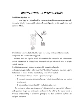
  • 1. DISTILLATION: AN INTRODUCTION Distillation is defined as: A process in which a liquid or vapor mixture of two or more substances is separated into its component fractions of desired purity, by the application and removal of heat. Distillation is based on the fact that the vapor of a boiling mixture will be richer in the components that have lower boiling points. Therefore, when this vapor is cooled and condensed, the condensate will contain more volatile components. At the same time, the original mixture will contain more of the less volatile material. Distillation columns are designed to achieve this separation efficiently. Although many people have a fair idea what “distillation” means, the important aspects that seem to be missed from the manufacturing point of view are that: • Distillation is the most common separation technique • It consumes enormous amounts of energy, both in terms of cooling and heating requirements • It can contribute to more than 50% of plant operating costs The best way to reduce operating costs of existing units, is to improve their efficiency and operation via process optimization and control. To achieve this improvement, a thorough understanding of distillation principles and how distillation systems are designed is essential.
  • 2. BASIC DISTILLATION EQUIPMENT AND OPERATION Main Components of Distillation Columns Distillation columns are made up of several components, each of which is used either to transfer heat energy or enhance material transfer. A typical distillation column contains several major components: • A vertical shell where the separation of liquid components is carried out • Column internals such as trays/plates and/or packing which are used to enhance components separations • A reboiler to provide the necessary vaporization for the distillation process • A condenser to cool and condensate the vapor leaving the top of the column • A reflux drum to hold the condensed vapor from the top of the column so that liquid (reflux) can be recycled back to the column. The vertical shell houses the column internals and together with the condenser and reboiler, constitutes a distillation column. A schematic of a typical distillation unit with a single feed and two product streams is shown below:
  • 3. Basic Operation and Terminology The liquid mixture that is to be processed is known as the feed and this is introduced usually somewhere near the middle of the column to a tray known as the feed tray. The feed tray divides the column into a top (enriching or rectification) section and a bottom (stripping) section. The feed flows down the column where it is collected at the bottom in the reboiler. Heat is supplied to the reboiler to generate vapor. The source of heat input can be any suitable fluid, although in most chemical plants this is normally steam. In refineries, the heating source may be the output streams of the columns. The vapor raised in the reboiler is re-introduced into the unit at the bottom of the column. The liquid removed from the reboiler is known as the bottoms product or simply, bottoms.
  • 4. The vapor moves up the column, and as it exits the top of the unit, it is cooled by a condenser. The condensed liquid is stored in a holding vessel known as the reflux drum. Some of this liquid is recycled back to the top of the column and this is called the reflux. The condensed liquid that is removed from the system is known as the distillate or top product. Thus, there are internal flows of vapor and liquid within the column as well as external flows of feeds and product streams, into and out of the column.
  • 5. TYPES OF DISTILLATION COLUMNS There are many types of distillation columns, each designed to perform specific types of separations, and each design differs in terms of complexity. Batch and Continuous Columns One way of classifying distillation column type is to look at how they are operated. Thus we have: • Batch and • Continuous columns Batch Columns In batch operation, the feed to the column is introduced batch-wise. That is, the column is charged with a ‘batch’ and then the distillation process is carried out. When the desired task is achieved, a next batch of feed is introduced. Continuous Columns In contrast, continuous columns process a continuous feed stream. No interruptions occur unless there is a problem with the column or surrounding process units. They are capable of handling high throughputs and are the most common of the two types. We shall concentrate only on this class of columns. Types of Continuous columns Continuous columns can be further classified according to:  The nature of the feed they are processing, • Binary column – feed contains only two components • Multi-component column-feed contains more than two components  The number of product streams they have
  • 6. Multi-product column-column has more than two components.  Where the extra feed exits when it is used to help with the separation • Extractive distillation-where the extra feed appears in the bottom product stream • Azeotropic distillation-where the extra feed appears at the top product stream  The type of column internals • Tray column-where trays of various designs are used to hold up the liquid to provide better contact between vapor and liquid, hence better separation • Packed column-where instead of trays, ‘packings’ are used to enhance contact between vapor and liquid
  • 7. COLUMN INTERNALS Trays and Plates The terms “trays” and “plates” are used interchangeably. There are many types of tray designs, but the most common ones are: Bubble cap trays A bubble cap tray has riser or chimney fitted over each hole, and a cap that covers the riser. The cap is mounted so that there is a space between riser and cap to allow the passage of vapor. Vapor rises through the chimney and is directed downward by the cap, finally discharging through slots in the cap, and finally bubbling through the liquid on the tray. Valve trays In valve trays, perforations are covered by liftable caps. Vapor flows lifts the cap, thus self creating a flow area for the passage of vapor. The lifting cap directs the vapor to flow horizontally into the liquid, thus providing better mixing than is possible in sieve trays. Sieve trays Sieve trays are simply metal plates with holes in them. Vapor passes straight upward through the liquid on the plate. The arrangement, number and size of the holes are design parameters. Because of their efficiency, wide operating range, ease of maintenance and cost factors, sieve and valve trays have replaced the once highly thought of bubble cap trays in many applications.
  • 8. Fig: (i) Bubble cap trays (ii) Valve trays (iii) Sieve trays
  • 9. Liquid and vapor flows in a tray column The next few figures show the direction of vapor and liquid flow across a tray, and across a column.
  • 10.
  • 11. Each tray has two conduits, one on each side, called ‘downcomers’. Liquid falls through the downcomers by gravity from one tray to the one below it. The flow across each plate is shown in the above diagram on the right. A weir on the tray ensures that there is always some liquid (hold up) on the tray and is designed such that the hold up is at a suitable height, e.g. such that the bubble caps are covered by liquid. Being lighter, vapor flows up the column and is forced to pass through the liquid, via the openings on each tray. The area allowed for the passage of vapor on each tray is called the active tray area. The picture below is a photograph of a section of a pilot scale column equipped with bubble capped trays. The tops of the 4 bubble caps on the tray can just be seen. The downcomer in this case is a pipe, and shown on the right. The frothing of the liquid on the active tray area is due to both passage of vapor from the tray below as well as boiling. As the hotter vapor passes through the liquid on the tray above, it transfers heat to the liquid. In doing so, some of the vapor condenses adding to the liquid on the tray. The condensate, however, is richer in the less volatile components than is in the vapor. Additionally, because of the heat input from the vapor, the liquid on the tray boils,
  • 12. generating more vapors. This vapor, which moves up to the next tray in the column, is richer in more volatile components. This continuous contacting between vapor and liquid occurs on each tray in the column and brings about the separation between low boiling point components and those with higher boiling points. Tray Designs A tray essentially acts as a mini-column, each accomplishing a fraction of the separation task. From this we can deduce that the more trays there are, the better the degree of separation and that overall separation efficiency will depend significantly on the design of the tray. Trays are designed to maximize vapor-liquid contact by considering the • Liquid distribution and • Vapor distribution On the tray. This is because better vapor-liquid contact means better separation at each tray, translating to better column performance. Less trays will be required to achieve the same degree of separation. Attendant benefits include less energy usage and lower construction costs. There is a clear trend to improve separations by supplementing the use of trays by additions of packings. Packings Packings are passive devices that are designed to increase the interfacial area for vapor- liquid contact. The following pictures show 3 different types of packing.
  • 13. These strangely shaped pieces are supposed to impart good vapor-liquid contact when a particular type is placed together in numbers, without causing excessive pressure drop across a packed section. This important because a high pressure drop would mean that more energy is required to drive the vapor up the distillation column. Packings versus Trays A tray column that is facing throughput problems may be de-bottlenecked by replacing a section of trays with packings. This is because:  Packings provide extra interfacial are for liquid-vapor contact  Efficiency of separation is increased for the same column height  Packed columns are shorter than trayed columns Packed columns are called continuous contact columns while trayed columns are called staged contact columns because of the manner in which vapor and liquid are contacted.
  • 14. COLUMN REBOILERS There are a number of designs of reboilers. It is beyond the scope of this set of introductory notes to deive into their design principles. However, they can be regarded as heat exchangers that are required to transfer enough energy to bring the liquid at the bottom of the column to boiling point. The following are examples of typical reboiler types.
  • 15. A novel development in reboiler design is the self-cleaning shell and tube heat exchangers by Klarex Technology for applications where heat exchange surfaces are prone to fouling by the process fluid. Particles are introduced into the process stream and these produce a scouring action on the heat exchange surfaces. An example is shown in the diagram on the below.
  • 16. DISTILLATION PRINCIPLES Separation of component from a liquid mixture via distillation depends on the differences in boiling points of the individual components. Also depending on the concentration of the components present, the liquid mixture will have different boiling point characteristics .therefore distillation processes depends on the vapor pressure characteristics of liquid mixtures.
  • 17. Vapor pressure and boiling The vapor pressure of a liquid at a particular temperature is the equilibrium pressure exerted by molecules leaving and entering the liquid surface .Here are some important point regarding the vapor pressure.  Energy input raises vapor pressure  Vapor pressure is related to boiling  A liquid is said to be boil when its vapor pressure equals the surrounding pressure  The ease with which liquid boils depends on its volatility  Liquid with high vapor pressures(volatile liquids) will boil at lower temperatures  The vapor pressure and hence the boiling point of a liquid mixture depends on the relative amount of the components in the mixture.  Distillation occurs because of the difference in the volatility of the components in the liquid mixture. The Boiling Point Diagram The boiling point diagram shows how the equilibrium compositions of the components in a liquid mixture very with temperature at a fixed pressure. Consider an example of a liquid mixture containing two components (A&B) - a binary mixture. This has the following boiling point diagram.
  • 18. The boiling point of A is that at which the mole fraction of A is 1. The boiling point of B is that at which the mole fraction of B is 0. In this example, A is more volatile component and therefore has a lower boiling point than B. The upper curve in the diagram is called the dew point curve while the lower is called the bubble point curve. The dew point is the temperature at which the saturated vapor starts to condense. The bubble point is the temperature at which the liquid starts to boil. The region above the dew point curve shows the equilibrium composition of the super heated vapor while the region below the bubble point curve shows the equilibrium composition of the sub cooled liquid. For example, when a sub cooled liquid with mole fraction of A=0.4(point A) heated its concentration remains constants until it reaches the bubble point (point B), When its starts to boil. The vapors evolved during the boiling has the equilibrium composition given by point C, Approximately 0.8 mole fraction A. this is a approximately 50% richer in A than the original liquid. This difference between liquid and vapor composition is the basis for distillation operations Relative volatility Relative volatility is a measure of the differences in volatility between two components, hence there boiling points. It indicates how easily or difficult a particular separation will be. The relative volatility of a component ‘i’ with respect to component ‘j’ is defined as αij=[yi/xi]/[yj/xj]
  • 19. yi=mole fraction of component ‘i’ in the vapor xi= mole fraction of component ‘i’ in the liquid. Thus if the relative volatility between 2 components is very close to one, it is an indication that they have very similar vapor pressure characteristics. This means that they have very similar boiling points and therefore, it will be difficult to separate the two components by distillation. VAPOUR LIQUID EQUILIBRIA Distillation columns are designed based on the boiling point properties of the components in the mixture being separated. Thus the sizes, particularly the height, of distillation columns are determined by the vapor liquid equilibrium data (VLE) for the mixtures. Vapor- Liquid Equilibrium (VLE) Curves Constant pressure VLE data is obtained from boiling point diagrams. VLE data for binary mixture is often presented as a plot, as shown in figure on the right. The VLE plots express the bubble point and the dew point of a binary mixture at constant pressure. The
  • 20. curved line is called the equilibrium line and describes the compositions of the liquid and vapor in equilibrium at some fixed pressure. This particular VLE plot shows a binary mixture that has a uniform vapor liquid equilibrium that is relatively easy to separate. The next two VLE plot below on the other hand, shows non-ideal system which will present more difficult separations. We can tell from the shapes of the curves and this will be explained further later on.
  • 21. The most intriguing VLE curves are generated by azeotropic systems. An azeotropic is a liquid mixture which when vaporized, produces the same composition as the liquid. The two VLE plots below show two different azeotropic systems, one with a minimum boiling point one with a maximum boiling point .In both plots, the equilibrium curve cross the diagonal lines, and this are azeotropic points where the azeotropes occur. In other words azeotropic systems give rise to VLE plots where the equilibrium curves crosses the diagonals. Note the shapes of the respective equilibrium lines in relation to the diagonal lines that bisect the VLE plots. Both plots are however, obtained from homogeneous azeotropic systems. An azeotrope that contains one liquid phase in contact with vapor is called a homogeneous azeotrope. A homogeneous azeotrope cannot be separated by conventional distillation. However vacuum distillation may be used as the lower pressure can shift the azeotropic point.
  • 22. Alternatively, an additional substance may added to shift the azeotropic point to a more ‘favorable‘position.  When the additional components appear in the appreciable amounts at the top of the column, the operation is called azeotropic distillation.  When the additional components appear mostly at the bottom of the column, the operation is called extractive distillation. The VLE curve as shown is also generated by an azeotropic system, in this case a heterogeneous azeotrope. Heterogeneous azeotrope can be identified by the ‘flat’ portion on the equilibrium diagram. They may be separated in 2 distillation columns since these substances usually form two liquid phases with widely differing compositions. The phases may be separated using settling tanks under appropriate conditions. Next, we will look at how VLE plots/data are used to design distillation columns. DISTILLATION COLUMN DESIGN As, mentioned, distillation columns are designed using VLE data for the mixtures to be separated. The vapor –liquid equilibrium characteristics (indicated by the shape of the equilibrium curve) of the mixture will determined the number of stages, and hence the number of trays, required for the separation. This is illustrated clearly by applying the McCabe- Thiele method to design a binary column.
  • 23. McCABE-THIELE DESIGN METHOD The McCabe- Thiele approach is a graphical one, and uses the VLE plot to determine the theoretical number of stages required to effect the separation of the binary mixture. It assumes constant molar overflow and this implies that:  Molal heats of vaporization of the components are roughly the same.  Heat effects (heats of solution, heat losses to and from column, etc) are negligible.  For every mole of vapor condensed, one mole of liquid is vaporized. The design procedure is simple. Given the VLE diagram of the binary mixture, operating lines are drawn first.  Operating lines define the mass balance relationships between the liquid and vapor phases in the column.  There is one operating for the bottom (stripping) section of the column, and on for the top (rectification or enriching) section of the column.  Use of the constant molar overflow assumption also ensures that the operating lines are straight lines. Operating line for the Rectification Section The operating line for the rectification section is constructed as follows. First the desired top product composition is located on VLE diagram , and a vertical line produced until it intersects the diagonal line that splits the VLE plot in half .A line with slope R/(R+1) is then drawn from this intersection point as shown in the diagram below.
  • 24. R is the ratio of reflux flow (L) to distillate flow (D) and is called the reflux ratio and is a measure of how much of the material going up the top of the column is return back to the column as the reflux. Operating line for the Stripping Section The operating line for the stripping section is constructed in a similar manner. However the starting point is the desired bottom product composition. A vertical line is drawn from this point to the diagonal line, and a line of slope Ls/Vs is shown in the diagram below.
  • 25. Ls is the liquid rate down the stripping section of the column, while Vs is the vapor rate up the stripping section of the column. Thus the slope of the operating line for the stripping section is a ratio between the liquid and vapor flows in that part of the column. Equilibrium and Operating Lines The McCabe- Thiele assumes that the liquid on a tray and the vapor above it are in equilibrium. How this is related to the VLE plot and the operating line is depicted graphically in the diagram on the below.
  • 26. A magnified section of the operating line for the stripping section is shown in relation to the corresponding n’th stage in the column.L’s are the liquid flows while V’s are the vapor flows. x and y denote liquid and vapor compositions and the subscripts denote the origin of the flows or compositions. That is ‘n-1’ will mean from the stage below the stage ’n’ while ‘n+1’ mean from the stage above the stage ’n’. The liquid in stage ‘n’ and the vapor above it are in equilibrium, therefore xn and yn lie on the equilibrium line. Since the vapor is carried to the tray above without changing composition, this is depicted as a horizontal line on the VLE plot. Its intersection with the operating line will give the composition of the liquid on the tray ‘n+1’ as the operating line defines the material balance on the trays. The composition of the vapor above the ‘n+1’ tray is obtained from the intersection of the vertical line from this point to the equilibrium line. Number of Stages and Trays Doing the graphical construction repeatedly will give rise to a number of ‘corner’ sections, and each section will be equivalent to a stage of the distillation. This is the basis of sizing distillation columns using the McCabe-Thiele graphical design methodology as shown in the following example.
  • 27. Given the operating line for both stripping and rectification sections, the graphical construction described above was applied. This particular example shows that 7 theoretical stages are required to achieve the desired separation. The required number of trays (as opposed to stages) is one less than the number of stages since the graphical construction includes the contribution of the reboiler in carrying out the separation. The actual number of trays required is given by the formula: (Number of theoretical trays) / (tray efficiency) A typical value for tray efficiency ranges from 0.5 to 0.7 and depends on a number of factors, such as the type of tray being used, internal liquid and vapor flow conditions. Sometimes additional trays are added (up to10%) to accommodate the possibility that the column may be under designed. The Feed Line (q-line) The diagram above also shows that the binary feed should be introduced at the 4th stage. However if the feed composition is such that it does not coincide with the intersection of the operating lines, this means that the feed is not a saturated liquid. The condition of the feed can deduce by the slope of the feed line or q-line. The q-line is that drawn between the intersection of the operating lines, and where the feed composition lies on the diagonal line. Depending on the state of feed, the feed lines have different slopes. For example, q=0 (saturated vapor) q=1 (saturated liquid) 0< q < 1 (mix of liquid and vapor) q>1 (sub cooled liquid) q<0 (superheated vapor) The q-lines for the various feed conditions are shown in the diagram.
  • 28. Using Operating Lines and the Feed Line in McCabe-Thiele Design If we have the information about the condition of the feed mixture, then we can construct the q-line and use in McCabe-Thiele design. However excluding the equilibrium line, only two other pairs of lines can be used in McCabe-Thiele procedure. These are • Feed- line and rectification section operating line. • Feed- line and stripping section operating line. • Stripping and rectification operating lines. This is because these pairs of lines determine the third. OVERALL COLUMN DESIGN Determining the number of stages required for desired degree of separation and the location of the feed tray is merely the first step in producing an overall distillation column design. Other things that need to be considered are tray spacing; column diameter; internal configuration; heating and cooling duties. All of these can lead to be conflicting design parameters. Thus, distillation design is an iterative procedure. If the conflicts are not resolved at the design stage, then the column will not perform well in pratice.The next set of notes will discuss the factors that can affect distillation column performance.
  • 29. FACTORS AFFECTING DISSTILATION COLUMN OPERATION The performance of a distillation column is determined by many factors, for example:  Feed conditions • State of feed • Composition of feed • Trace elements that can severely effect the VLE of liquid mixtures  Internal liquid and feed flow conditions  State of trays (packings)  Weather conditions Some of these will be discussed below to give an idea of complexity of the distillation process. Feed conditions The state of the feed mixture and feed composition affects the operating lines and hence the number of stages required for separation. It also affects the location of feed tray. During operation, if the deviations from design specifications are excessive, then the column may no longer be able handle the separation task. To overcome the problems associated with the feed, some column are designed to have multiple feed points when the feed is expected to containing varying amounts of components.
  • 30. Reflux conditions As the reflux ratio is increased, the gradient of operating line for the rectification moves towards a maximum value of 1. Physically, what this means is that more and more liquid that is rich in the more volatile components are being recycled back to the column. Separation then becomes better & thus less trays are needed to achieve the same degree of separation. Minimum trays are required under total reflux conditions, i.e. there is no withdrawal of distillate. On the other hand, as reflux is decreased, the operating line for the rectification section moves towards the equilibrium line. The ‘pinch’ between operating and equilibrium line becomes more pronounced and more and more trays are required. This is easy to verify using the Mc Thiele method. The limiting conditions occur at minimum reflux ratio, when an infinite number of trays will be required to effect the separation. Most columns are designed to operate between 1.2 to 1.5 times the minimum reflux ratio because this is approximately the region of minimum operating costs (more reflux mean higher reboiler duty). Vapor Flow Conditions Adverse vapor flow conditions can cause
  • 31. Foaming • Entrainment • Weeping/dumping • Flooding Foaming Foaming refers to the expansion of liquid due to the passage of vapor or gas. Although it provides high interfacial liquid vapor contact, excessive foaming often leads to liquid build up on trays. In some cases, foaming may be so bad that the foam mixes with liquid on the tray above. Whether foaming will occur depends primarily on physical properties of liquid mixture, but is sometimes due to tray designs and condition. Whatever the cause, separation efficiency is always reduced. Entrainment Entrainment refers to the liquid carried by the vapor up to the tray above & is again caused by high vapor flow rates. It is detrimental because tray efficiency is reduced; lower volatile material is carried to a plate holding liquid of higher volatility. It could also contaminate high purity distillate. Excessive entrainment can lead to flooding. Weeping/dumping This phenomenon is caused by low vapor flow. The pressure exerted by the vapor is insufficient to hold up the liquid on the tray. Therefore, liquid starts to leak through perforations. Excessive weeping will lead to dumping. That is the liquid on all trays will crash (dump) through to the base of the column (via a domino effect) and the column will have to be re-started. Weeping is indicated by a sharp pressure drop in the column and reduced separation efficiency. Flooding Flooding is brought about by excessive vapor flow, causing liquid to be entrained in the vapor up the column. The increased pressure from excessive vapor also backs up the
  • 32. liquid in the down comer, causing an increase in liquid hold up on the plate above. Depending on the degree of flooding, the maximum capacity of the column may be severely reduced. Flooding is dedicated by sharp increases in column differential pressure and significant decrease in separation efficiency. Column Diameter Most of the above factors that affect column operation is due to vapor flow conditions, either excessive or too low. Vapor flow velocity is dependent on column diameter. Weeping determines the minimum vapor flow required while flooding determines the maximum vapor flow allowed, hence column capacity. Thus, if the column diameter is not sized properly, the column will not perform well. Not only will operational problems occur, the desired separation duties may not be achieved. State of Trays and Packing Remember that the actual number of trays required for a particular separation duty is determined by the efficiency of the plate, and the packings if packings are used. Thus any factors that cause a decrease in tray efficiency will also change the performance of the column. Tray efficiencies are affected by fouling, wear and tear and corrosion, and the rates at which these occur depends on the properties of the liquid being processed. Thus appropriate materials should be specified for tray construction. Weather conditions Most distillation columns are open to the atmosphere. Although many of the columns are insulated, changing weather conditions can still affect column operation. Thus the reboiler must be appropriately sized to ensure that enough vapors can be generated during cold and windy spells and that it can be turned down sufficiently during hot seasons. The same applies to condensers. These are some important factors that can cause poor distillation performance. Other factors include changing operating conditions & throughputs, brought about by changes in upstream conditions & changes in the demand of the products. All these factors, including the associated control system should be considered at the design stages
  • 33. because once a column is built & installed, nothing can be done to rectify the situation without incurring significant costs. The control of distillation columns is a field in its own right, but that’s another story.