SlideShare una empresa de Scribd logo
1 de 20
Descargar para leer sin conexión
Electric Circuits                                          Name:


                                     Electric Potential Difference
Read from Lesson 1 of the Current Electricity chapter at The Physics Classroom:
     http://www.physicsclassroom.com/Class/circuits/u9l1a.html
     http://www.physicsclassroom.com/Class/circuits/u9l1b.html
     http://www.physicsclassroom.com/Class/circuits/u9l1c.html
MOP Connection:          Electric Circuits: sublevels 2 and parts of 3

Review:
1. Electric field is defined as the aura about the space surrounding a charged object which exerts an
    electrical influence upon other charged objects in that space. The direction of the electric field
    vector is defined as the direction which a positive test charge would be accelerated. Potential
    energy is the energy stored in an object due to the position of that object.

A Gravitational Analogy:
2.  Two diagrams are shown at the right.
     In diagram A, a mass is held at an
     elevated position. When let go of, the
     mass falls from point A to point B.
     In diagram B, the mass is originally at
     point A and a person moves it back up
     to point B.

     For each diagram, indicate if work is
     done by a non-conservative force in
     moving the object from its initial
     position (point A) to its position at point
     B. Finally, indicate the position of
     greatest gravitational potential energy.
                                                   Wnc done on mass:         Wnc done on mass:
     Circle the answers in the space below
     the diagrams.                                    Yes or No                 Yes or No
                                                   Highest PE: A or B        Highest PE: A or B

3.   The following diagrams show an electric field and two points - labeled A and B - located within the
     electric field. A positive test charge is shown at point A. For each diagram, indicate whether work
     must be done upon the charge to move it from point A to point B. Finally, indicate the point (A or B)
     with the greatest electric potential energy and the greatest electric potential (PE/charge).


      Work done on test charge? Yes or              No    Work done on test charge? Yes or        No
      Potential energy is greatest at:   A         B      Potential energy is greatest at:   A   B
      Electric potential is greatest at: A         B      Electric potential is greatest at: A   B


      Work done on test charge? Yes or              No    Work done on test charge? Yes or        No
      Potential energy is greatest at:   A         B      Potential energy is greatest at:   A   B
      Electric potential is greatest at: A         B      Electric potential is greatest at: A   B


© The Physics Classroom, 2009                                                                      Page 1
Electric Circuits


3.   When work is done on a positive test charge to move it from one location to
     another, potential energy _________ (increases, decreases) and electric
     potential _________ (increases, decreases).
     When a positive test charge naturally moves from one location to another
     (without the exertion of a non-conservative force), potential energy _________
     (increases, decreases) and electric potential _________ (increases, decreases).
4.   The diagram at the right shows a light bulb connected to a 12-V car
     battery. The + and - terminals are shown.
     a. As a + charge moves through the battery from D to A, it ________
         (gains, loses) potential energy and ________ (gains, loses) electric
         potential. The point of highest energy within a battery is the ______
         (+, - ) terminal.
     b.    As a + charge moves through the external circuit from A to D, it
           ________ (gains, loses) potential energy and ________ (gains, loses)
           electric potential. The point of highest energy within the external
           circuit is closest to the ______ ( +, - ) terminal.
     c.    Use >, <, and = signs to compare the electric potential (V) at the four
           points of the circuit.
                  VA               VB               VC               VD

5.   The role of a battery in an electrical circuits can be described in three different ways. First, it is the
     energy supply. Second, the energy supplied by the battery is required to do work upon the charge
     to move it against the electric field from the negative terminal to the positive terminal. And third, by
     moving the charge against the field from negative to positive terminal, the battery establishes an
     electric potential difference across the two ends of the external circuit.
     Without a potential difference between two locations, charge will not move. When there is an
     electric potential between two locations, charge will move
     from the location of high potential to the location of low
     potential. The amount of potential difference (ΔV) between
     two locations is related to the work done in moving an
     amount of charge (Q) from the low potential to the high
     potential location.
                                            Work
                    ΔV = Vhigh - Vlow =
                                             Q
     a.   It takes _____ J of work to move 1 C of charge from the - to the + terminal of a 1.5-volt battery.
     b.   It takes _____ J of work to move 2 C of charge from the - to the + terminal of a 12-volt battery.
     c.   It takes 18 J of work to move _____ C of charge from the - to the + terminal of a 12-volt battery.
                                    !
     d.   It takes 12 J of work to move 2 C of charge from the - to the + terminal of a _____-volt battery.
     e.   It takes _____ J of work to move _____ C of charge from the - to the + terminal of a 12-volt battery.

6.   In the battery, energy is supplied to the charge to move it
     from low potential (- terminal) to high potential (+
     terminal). Once at the + terminal, the charge
     spontaneously moves through the external circuit, losing
     energy as it passes through each electrical device. The
     electric potential which is gained by the charge when it
     passes through the battery is lost by the charge as it moves
     through the external circuit. These gains and losses in
     electric potential are often represented using an electric
     potential diagram. For the circuit at the right, complete the
     electric potential diagram, showing the relative potential of
     locations A, B, C, D, E, and F.


© The Physics Classroom, 2009                                                                           Page 2
Electric Circuits                                         Name:


                                Electric Circuits and Electric Current
Read from Lesson 2 of the Current Electricity chapter at The Physics Classroom:
     http://www.physicsclassroom.com/Class/circuits/u9l2b.html
     http://www.physicsclassroom.com/Class/circuits/u9l2c.html
     http://www.physicsclassroom.com/Class/circuits/u9l2e.html

MOP Connection:           Electric Circuits: sublevel 1

1.   To maintain a charge flow in an electric circuit, at least two requirements must be met:
     #1: An external energy supply (e.g., battery, wall outlet, generator, etc.) to pump the charge
         through the internal circuit and establish a potential difference across the circuit.
     #2: The external circuit must make up a "closed conducting loop" between the + and - terminal.
     Utilize your understanding of these requirements to state whether charge would flow through the
     following circuits. If there is no charge flow, then explain why not.


                    Charge Flow: Yes or No?                         Charge Flow: Yes or No?
                         Explanation:                                      Explanation:


                    Charge Flow: Yes or No?                         Charge Flow: Yes or No?

                         Explanation:                                      Explanation:


Charge flow in a circuit is often compared to water flow. For water to flow between two points, there
must be a difference in water pressure between the points. Water pressure is like electric potential.
Water will only flow through a pipe if there is a difference in potential between the two ends. Charge
will only flow through a wire if there is an electric potential difference across its ends.


© The Physics Classroom, 2009                                                                      Page 3
Electric Circuits


2.   Consider the two requirements for an electric circuit (described in question #1). When a light bulb is
     burned out and no longer works, requirement #______ is not met. When a battery no longer works,
     requirement #______ is not met.

3.   What do you believe? Respond to the following statements as being TRUE or FALSE.
     a. When a battery no longer works, it is out of charge and must be re-charged    T or F
        before it can be used again.
     b.   A battery can be a source of charge in a circuit. The charge which flows              T or F
          through the circuit originates in the battery.
     c.   Charge becomes used up as it flows through a circuit. The amount of charge            T or F
          which exits a light bulb is less than the amount which enters the light bulb.
     d. Charge flows through circuits at very high speeds. This explains why the                T or F
        light bulb turns on immediately after the wall switch is flipped.
     e.   Commonwealth Edison supplies millions and millions of electrons to our                T or F
          homes everyday.

4.   A current is said to exist whenever _____.
     a. a wire is charged                            b. a battery is present
     c. electric charges are unbalanced              d. electric charges move in a loop

5.   As a quantity, electric current is defined as the _____.
     a. amount of charge present in a circuit         b. potential energy per charge
     c. rate at which charge moves through a cross-sectional area of a wire
     d. speed at which charge moves from one location to another location

6.   Complete the statements:
     a. A current of one ampere is a flow of charge at the rate of
        _______ coulomb per second.
     b.   When a charge of 8 C flows past any point along a circuit
          in 2 seconds, the current is ________ A.
     c.   If 5 C of charge flow past point A (diagram at right) in 10
          seconds, then the current is _________ A.
     d. If the current at point D is 2.0 A, then _______ C of charge
        flow past point D in 10 seconds.
     e.   If 12 C of charge flow past point A in 3 seconds, then 8 C of charge will flow past point E in
          ________ seconds.
     f.   TRUE or FALSE:
             The current at point E is considerably less than the current at point A since charge is being
             used up in the light bulbs.


7.   Which sentence best describes what happens to charge as it moves through an electric circuit?
     a. Charge is consumed or used up.
     b. Charge is re-energized and recycled.

8.   Which sentence best describes how fast charge moves through an electric circuit?
     a. Charge moves very fast; faster than any human can run.
     b. Charge moves very slow; slower than the proverbial snail.

9.   When you turn on the room lights, they light immediately. This is best explained by the fact that
     ____.
     a. electrons move very fast from the switch to the light bulb filament.
     b. electrons present everywhere in the circuit move instantly.


© The Physics Classroom, 2009                                                                          Page 4
Electric Circuits                                            Name:


                                            Electrical Resistance
 Read from Lesson 3 of the Current Electricity chapter at The Physics Classroom:
      http://www.physicsclassroom.com/Class/circuits/u9l3a.html
      http://www.physicsclassroom.com/Class/circuits/u9l3b.html
      http://www.physicsclassroom.com/Class/circuits/u9l3c.html

 MOP Connection:          Electric Circuits: sublevels 4 and 5

Physics Idea:   As charge flows through an electric circuit, it
                encounters resistance. Resistance is a measure of
                the amount of hindrance to the flow of charge.

 1.   The cause of resistance to the flow of charge within an
      electrical wire is _____.
      a. mobile charge carriers collide with atoms of the resistor
      b. mobile charge carriers have mass (possess inertia) which resists their motion
      c. the electric field which causes charge flow diminishes with distance
      d. charge is consumed or used up as it flows through the wire

 2.   Resistance is quantifiable - that is, it can be measured and calculated. The standard metric unit used
      to express the amount of electrical resistance is the ____.
      a. Joule               b. Watt                    c. Volt                d. Amp       e. Ohm

 3.   For the following pairs of wire descriptions, choose the wire which has the greatest resistance.
      Resistance to charge flow will be greatest in … . (Circle the best answer.)
      a. … a wire which is thin                       … a wire which is thick
      b. … a wire which is long                       … a wire which is short
      c. … a wire which is made of copper             … a wire which is made of plastic
      d. … a wire which is made of copper             … a wire which is made of silver

 4.   The rate at which charge flows through a circuit is ___________ to the resistance.
      a. inversely related b. directly related      c. not related

 5.   For the following pairs of circuit descriptions, choose the circuit which has the greatest current.
      Given that all other factors are equal, the current will be greatest in a circuit which has … .
      a. … a high resistance                           … a low resistance
      b. … wires which are long                        … wires which are short
      c. … wires which are wide                        … wires which are thin
      d. … 12-gauge wires (1/12 inch diameter) … 14-gauge wires (1/14th inch diameter)
                                   th


      e. … copper wiring                               … silver wiring

 6.   Resistance is not the only variable which effects the current in an electric circuit. The current is also
      effected by the electric potential difference (Δ V) impressed across its ends. The electric potential
      difference is simply the battery voltage. As the battery voltage is increased (by swapping in higher
      voltage batteries), the current is _____________________ (increased, decreased).

 The relationship between electric potential difference (ΔV), resistance (R) and current (I) is given be the
 equation.
                                                         "V
                                                    I=
                                                          R
 This equation, sometimes referred to as the Ohm's law equation, is often written as ΔV = I•R. Like all
 equations in physics, it can be used as a recipe for problem-solving and an equation to guide one's
 thinking about how an alteration in one ! variable effects another variable.


 © The Physics Classroom, 2009                                                                           Page 5
Electric Circuits


7.    A circuit is set up such that it has a current of 8.0 amps. What would be the new current if ….
      a. … the resistance (R) is increased by a factor of 2?
      b. … the resistance (R) is increased by a factor of 4?
      c. … the resistance (R) is decreased by a factor of 3?
      d. … the battery voltage (Δ V) is increased by a factor of 3?
      e. … the battery voltage (ΔV) is decreased by a factor of 2?
      f. … the resistance (R) is increased by a factor of 2 and the battery
            voltage (ΔV) is decreased by a factor of 2?
      g. … the resistance (R) is decreased by a factor of 4 and the battery
            voltage (ΔV) is increased by a factor of 3?

8.    Express your understanding of the use of the I = ΔV / R equation by filling in the following blanks.
      a. An electrical device with a resistance of 2.0 Ω has an electric potential difference of 6.0 V
          impressed across it; the current in the device is _____ amperes.
      b. An electrical device with a resistance of 3.0 Ω has an electric potential difference of ______ V
          impressed across it; the current in the device is 4.0 amperes.
      c.  An electrical device with a resistance of _____ Ω has an electric potential difference of 120 V
          impressed across it; the current in the device is 6.0 amperes.

9.    Resistors are electrical devices designed to have a specific resistance. They are inserted in circuits to
      modify the actual current flowing through the circuit. When diagramming a circuit, a resistor is
      represented by the symbol                  .
      Which of the resistors in the two circuits (A or B) has the greatest resistance? Calculate the value.


10.   Use arrows to show the direction of conventional current flow through the following circuits and
      use the I = ΔV / R equation to fill in the blanks.


      The three new circuit symbols introduced in the above diagrams are


            Power Supply                 Voltmeter (for measuring ΔV)         Ammeter (for measuring I)


© The Physics Classroom, 2009                                                                            Page 6
Electric Circuits                                           Name:


                                      Electrical Power and Energy
Read from Lessons 2 and 3 of the Current Electricity chapter at The Physics Classroom:
     http://www.physicsclassroom.com/Class/circuits/u9l2d.html
     http://www.physicsclassroom.com/Class/circuits/u9l3d.html
MOP Connection:           Electric Circuits: sublevel 3

Review:
1. The electric potential at a given location in a circuit is the amount of _____________ per ___________
    at that location. The location of highest potential within a circuit is at the _______ ( +, - ) terminal of
    the battery. As charge moves through the external circuit from the ______ ( +, - ) to the ______ ( +,
    - ) terminal, the charge loses potential energy. As charge moves through the battery, it gains
    potential energy. The difference in electric potential between any two locations within the circuit is
    known as the electric potential difference; it is sometimes called the _____________________ and
    represented by the symbol ______. The rate at which charge moves past any point along the circuit
    is known as the ___________________ and is expressed with the unit ________________.

The diagram at the right depicts an electric circuit in a car. The rear
defroster is connected to the 12-Volt car battery. Several points are labeled
along the circuit. Use this diagram for questions #2-#6.
2.   Charge flowing through this circuit possesses 0 J of potential energy
     at point ___.

3.   The overall effect of this circuit is to convert ____ energy into ____ energy.
     a. electrical, chemical                           b. chemical, mechanical
     c. thermal, electrical                            d. chemical, thermal
4.   The potential energy of the charge at point A is ___ the potential energy at B.
     a. greater than       b. less than             c. approximately equal to
5.   The + charge gains potential energy as it moves between points ___ and ___.
     a. A and B            b. B and C             c. C and D             d. D and A           e. none of these
6.   The + charge loses potential energy as it moves between points ___ and ___.
     a. A and B            b. B and C              c. C and D             d. D and A          e. none of these

7.   The rate at which energy is delivered to a circuit by the energy source or the rate at which energy is
     consumed by an electrical device is known as the electric ______.
     a. current            b. potential             c. voltage              d. power
8.   The unit of electric power is the _____.
     a. Ampere              b. Volt                  c. Watt                  d. Joule
9.   Mechanical power (discussed in a previous unit) is the rate at which work is done on an object.
     Electrical power is the rate at which work is done on a charge (by the battery) or on an electrical
     device (by the charge). In terms of an equation, it is … . (Fill in the numerator and the
     denominator.)


     a.   A 60-Watt light bulb uses up ____________ J of energy when left on for _____ 1 hour (3600 s).
     b.   A 60-Watt light bulb uses up ____________ J of energy when left on for _____ 4 hours.
     c.   A 1500-Watt hair dryer uses up ____________ J of energy when used for _____ 5 min (300 s).
     d.   A 120-Watt fan uses up ____________ J of energy when left on for _____ a day.


© The Physics Classroom, 2009                                                                            Page 7
Electric Circuits


10. Substitution of other electrical equations ( I = Q/t and ΔV = I•R and ΔV = W/Q ) into the power
    equation yields the following three equations.
                    P = I•ΔV                      P = I2•R                     P = ΔV2 / R
     Use these equations to solve the following problems.
     a. Calculate the resistance of a toaster oven if its power is 800 W when connected to a 110-V outlet.


     b. Calculate the resistance of the 1000 W microwave oven which gets plugged into to a 110-V outlet.


     c. The TI-84 calculator uses four 1.5-V batteries and has a power of 0.0008 W. What is the current?


11. The following two circuits consist of a power supply, an ammeter (for measuring current), and a
    light bulb. Use >, <, and = symbols to compare the electric potential at A to B and at C to D.
    Indicate whether the devices add energy to or remove energy from the charge. Finally, fill in all
    blanks.

                                                                                              VA ____ VB
                                                                                               (>, <, or =)

                                                                                              VC ____ VD
                                                                                               (>, <, or =)

                                                                                              VB ____ VD
                                                                                               (>, <, or =)


12. TRUE or FALSE:             A kilowatt-hour is a unit of power.

13. Alfredo deDarke often leaves household appliances on for no good reason (at least according to his
    parents). The deDarke family pays 10¢/kilowatt-hour (i.e., $.15/kW•hr) for their electrical energy.
    Express your understanding of dollar power by filling in the following table.
          Power Rating                  Time                  Energy Used                    Costs
             (Watt)                     (hrs)                (kilowatt-hour)                  ($)
           60 Watt Bulb                   1                   0.060 kW•hr                    $0.009
           60 Watt Bulb                   4

         Ten 60 Watt Bulb                24

           60 Watt Bulb                                                                       $10

        7 Watt Night Light               168

        7 Watt Night Light              7760

14. People often claim that an electrical appliance "uses up electricity." Explain what is actually being
    "used up" and what becomes of this thing which is being used up.


© The Physics Classroom, 2009                                                                           Page 8
Electric Circuits                                             Name:


                                Mathematical Relationships in Circuits
Read from Lessons 2 and 3 of the Current Electricity chapter at The Physics Classroom:
     http://www.physicsclassroom.com/Class/circuits/u9l2c.html
     http://www.physicsclassroom.com/Class/circuits/u9l2d.html
     http://www.physicsclassroom.com/Class/circuits/u9l3c.html
     http://www.physicsclassroom.com/Class/circuits/u9l3d.html
MOP Connection:            Electric Circuits: sublevels 5 and 6
1.   Matching: Identify the units on the following electrical quantities by placing a letter in the blank.
     The unit of charge is the ____.                                       Choices: A. Coulombs
     The unit of electric potential is the ____.                                     B. Amperes
     The unit of power is the ____.                                                  C. Volts
     The unit of potential energy is the ____.                                       D. Ohms
     The unit of current is the ____.                                                E. Joules
     The unit of resistance is the ____.                                             F. Watts

2.   An electric potential diagram is a useful means of representing the potential of a positive charge as
     it moves around a circuit. The electric potential of a charge at strategic locations in a circuit is
     represented on a chart. Points on the circuit where the charge has the highest potential are located
     highest on the chart; points of lowest potential are located lowest on the charts. At some points on
     the circuit, charges have approximately the same amount of potential. Construct electric potential
     diagrams for the following circuits. Label the points.
      a.                                                     b.


3.   Given the circuit at the right with the listed
     current and resistance values, determine the
     electric potential at the indicated positions.
     Note that you are to find the electric potential
     (or voltage) and NOT the electric potential
     difference (or voltage drop).
     VA =              V       VB =               V

     VC =              V       VD =               V

     VE =              V

4.   Determine the following quantities for the circuit in question #3 above. PSYW
     a. The overall power.                          b. The power of the 6-ohm light bulb.


     c. The overall resistance.                         d. The energy used by the circuit in 10 minutes.


© The Physics Classroom, 2009                                                                              Page 9
Electric Circuits


Show your work for the following problems.
5. a. Determine the amount of energy used when listening to your 5.0-Watt IPod Nano for 10 hours.


     b. Determine the resistance of the IPod if it uses a 5.2 Volt battery.


     c. What quantity of charge passes through the IPod battery during this 10-hr time period?


6.   a. Calculate the energy used and current drawn by a 200-W window fan when plugged into a 110-V
     outlet and left on for an 8-hr time period.


     b. Calculate the energy used and the current drawn by a 3400-W air conditioner which is wired to a
     220-V circuit and left on for an 8-hr time period.


7.   A 2000-W hand dryer in a public bathroom at a zoo runs for 30 seconds per cycle. At a cost of 13
     cents per kW•hr, determine the cost of running the dryer 200 times in a day.


     What is the annual cost of the hand dryer assuming it is used on average 200 times per day?


     Calculate the resistance and the current for the hand dryer if it is connected to a 220-V circuit.


© The Physics Classroom, 2009                                                                         Page 10
Electric Circuits                                          Name:


                                               Series Circuits
Read from Lesson 4 of the Current Electricity chapter at The Physics Classroom:
     http://www.physicsclassroom.com/Class/circuits/u9l4a.html
     http://www.physicsclassroom.com/Class/circuits/u9l4b.html
MOP Connection:          Electric Circuits: sublevels 7, 9 and 11

1.   Electrical devices in circuits can be connected to each other in a number of different ways. The two
     most common connections are series connections and parallel connections. Observe the electrical
     wiring below. Indicate whether the connections are series or parallel.


                     Series or Parallel?                                Series or Parallel?

2.   Two electric circuits are diagrammed below. For each circuit, indicate which two devices are
     connected in series and which two devices are connected in parallel.


     Series                                               Series
     Parallel                                             Parallel

3.   Comparing Series vs. Parallel Circuits
     Fill in the table below to indicate the manner in which series and parallel circuits differ.
                                                               Series Circuit           Parallel Circuit
      a.   Definition: The pathway by which charge
           loops around the circuit is characterized
           by __________ pathway.
      b.   Observation: If one light bulb goes out,
           the other light bulbs _________.
      c.   Observation: As the number of resistors
           is increased, the overall current ______.
      d.   Observation: As the number of resistors
           is increased, the overall resistance ______.


© The Physics Classroom, 2009                                                                         Page 11
Electric Circuits


4.   The following diagrams represent circuits consisting of two electrical devices connected in series.
     For each diagram, fill in the blanks to show the voltage drop across the designated device.


5.   Consider the following two diagrams of series circuits. For each diagram, use arrows to indicate the
     direction of the conventional current. Then, make comparisons of the voltage and the current at the
     designated points for each diagram.


                      VA _____ VG                                           VA _____ VF
                       (>,<, or =)                                           (>,<, or =)
                       VB _____ VC                                          VB _____ VC
                        (>,<, or =)                                          (>,<, or =)
                       VB _____ VF                                          VD _____ VF
                        (>,<, or =)                                          (>,<, or =)
                       IA _____ IG                                           IA _____ IF
                        (>,<, or =)                                           (>,<, or =)


5.   Express your understanding of equivalent resistance by filling in the blanks.
     Having two 4-Ω resistors in series is equivalent to having one _____-Ω resistor.
     Having three 4-Ω resistors in series is equivalent to having one _____-Ω resistor.
     Having four 4-Ω resistors in series is equivalent to having one _____-Ω resistor.

6.   TRUE or FALSE:
            Three light bulbs are connected in series. The filament of one of the light bulbs burns out.
            The remaining two light bulbs will still be lit; yet, their brightness will be noticeably less.


© The Physics Classroom, 2009                                                                          Page 12
Electric Circuits                                       Name:


7.   Analyze the following circuit and determine the equivalent or total resistance. Then determine the
     current at the ammeter location.


            Rtot =                                              Rtot =

            I=                                                  I=


8.   For the following diagrams, utilize the concept of equivalent resistance and Ohm's Law in order to
     fill in the blank.


© The Physics Classroom, 2009                                                                    Page 13
Electric Circuits


9.   Compare circuits X and Y. Consider circuits X and Y
     below. Each circuit is powered by the same battery
     and contains identical resistors. Circuit X has one
     resistor and circuit Y has two resistors. The equivalent
     resistance of circuit X will be __________ (> or < or =)
     that of circuit Y. The current in the battery in X will be
     __________ (> or < or =) that in the battery in Y.


10. Three identical light bulbs are connected to a battery as shown below.
    Which adjustments could be made to the circuit that would increase
    the current being measured at X? Circle all that apply.
    a. Increase the resistance of one of the bulbs.
    b. Decrease the resistance of two of the bulbs.
    c. Increase the resistance of two of the bulbs.
    d. Decrease the voltage of the battery.
    e. Increase the voltage of the battery.
    f. Remove one of the bulbs.


11. Three identical light bulbs are connected to a battery as shown below.
    W, X,Y and Z represent locations along the circuit. Which one of the
    following statements is true?
    a. The potential difference between X and Y is greater than that
         between Y and Z.
    b. The potential difference between X and Y is greater than that
         between Y and W.
    c.   The potential difference between Y and Z is greater than that
         between Y and W.
    d. The potential difference between X and Z is greater than that between Z and W.
    e.   The potential difference between X and W is greater than that across the battery.
    f.   The potential difference between X and Y is greater than that between Z and W.


12. Three identical light bulbs are connected to a battery as shown below.
    Which one of the following statements is true?
    a. All three bulbs will have the same brightness.
    b. The bulb between X and Y will be the brightest.
    c. The bulb between Y and Z will be the brightest.
    d. The bulb between Z and the battery will be the brightest.
     Justify your answer to this question using the language of physics.


13. Compare a circuit with three light bulbs to a circuit with two light bulbs. All light bulbs are
    identical. In which circuit will the overall power be the greatest? Intelligently defend your answer.


© The Physics Classroom, 2009                                                                      Page 14
Electric Circuits                                          Name:


                                             Parallel Circuits
Read from Lesson 4 of the Current Electricity chapter at The Physics Classroom:
     http://www.physicsclassroom.com/Class/circuits/u9l4a.html
     http://www.physicsclassroom.com/Class/circuits/u9l4c.html
MOP Connection:          Electric Circuits: sublevels 8, 10 and 11

Review:
1. A circuit in which all charge follows a single pathway is a ____ circuit; a circuit in which charge
    follows multiple pathways is a ____ circuit.
    a. series, parallel                            b. parallel, series

2.   For a parallel circuit: as the number of resistors being used within the same parallel circuit increases,
     the overall resistance value _____________________________ (increases, decreases) and the overall
     current value _____________________________ (increases, decreases).

3.   Household circuits are connected in parallel so that _____. Select all that apply.
     a. houses get the same effect with less current and thus save on energy costs.
     b. the turning off of one appliance does not result in the shut down of others.
     c. the hazard of electrocution and overheating of circuits is avoided.

Water Analogy:
4. When the water flow (or charge flow) is divided into two or more separate pathways (as in a parallel
    circuit) the sum of the current in each individual pathway equals the total current. Utilize this
    principle to fill in the blanks in the following two diagrams. The meters in the diagram are
    measuring water flow rates in gallons per minute ("gpm").


5.   Apply the same principle to fill in the blanks in the following diagrams for charge flow (i.e., current)
     through a parallel circuit.


© The Physics Classroom, 2009                                                                         Page 15
Electric Circuits


                                             The Staircase Analogy
     Electric charge dividing into multiple pathways in a parallel circuit is analogous to people walking
     down stairs which divide up into separate paths.
     Imagine being at a large shopping mall; you are descending a rather wide stairway when all of a
     sudden it breaks up into several smaller stairways. Being in a hurry, you scan the different
     pathways down the stairs to see which path is least crowded. You finally decide that the left
     stairway is least crowded and make a "dash" towards it. You know that your "flow rate" will be
     greatest along the stairway with the least resistance. When the "people flow" divides up into
     multiple pathways, each pathway has the same change in height (or same gravitational potential
     drop); yet, the pathway which offers the least resistance will have the greatest flow rate.
     In an analogous manner, as charge flow divides up into multiple pathways in a parallel circuit, each
     pathway has the same electric potential drop; yet, the pathway with the least resistance will have
     the greatest rate of charge flow (i.e., current).
6.   In the following circuits, fill in the blanks to indicate the current through the different pathways.
     Calculate the resistance of each resistor. Then rank the resistance of the resistors (labeled A, B, and
     C) in order from smallest to largest.


                    Ranking of Resistance                            Ranking of Resistance
                      ____ < ____ < ____                               ____ < ____ < ____
7.   A three-resistor parallel circuit is created. The resistance of the resistors are 3 Ω, 6 Ω, and 9 Ω.
     Suppose that one observes the current through the 3 Ω resistor to be 6 Amperes. The voltage drop
     across this 3 Ω resistor must be _______ V. This provides sufficient evidence to conclude that the
     voltage drop across the 6 Ω resistor is _______ V and the voltage drop across the 9 Ω resistor is
     _________ V. Therefore, the current in the 6 Ω resistor is ________ Amperes and the current in the 9
     Ω resistor is _________ Amperes. When these three branch currents combine, one would observe
     that the current in the ___________ V battery is _________ Amperes. In summary:
                  R1 = 3 Ω                       R2 = 6 Ω                             R3 = 9 Ω
               I1 = 6 Amps                  I2 = _____ Amps                      I1 = _____ Amps
              ΔV1 = _____ V                  ΔV2 = _____ V                        ΔV3 = _____ V

           Ibattery = _____ Amps            ΔVbattery = _____ V            ΔVbattery / Ibattery = ________

8.   Consider the circuit at the right.
     a. There is a voltage drop of _____V across each 2-Ω resistor.
     b.   By Ohm's law, the current in each 2-Ω resistor is _____ amps.
     c.   The current through the battery is ______ amps.
     d. The resistors in parallel offer a combined resistance of _______ Ω
        to the charge being pumped by the battery.


© The Physics Classroom, 2009                                                                            Page 16
Electric Circuits                                            Name:


                                                 Equivalent Resistance
     Devices connected in parallel offer a resistance to the flow of charge through the circuit. The total
     resistance (or equivalent resistance) is related to the resistance of the individual devices which are
     connected in parallel. The equivalent resistance can be determined with the equation
                                            1         1     1   1
                                        Requivalent = R1 + R2 + R3

     The electric potential difference across each branch is the product of the equivalent resistance and
     the total current (outside the branches).

Use the diagram below at the right in order to answer questions #9-#13. PSYW
9.   Determine the equivalent resistance of the circuit at
     the right.


10. Determine the overall current in the circuit (as
    determined at position A or H).


11. Determine the electric potential difference (i.e. voltage drop) across the 5-Ω resistor (from B to C).


12. Determine the current through the 5-Ω resistor (from B to C).


13. Determine the current through the 7-Ω resistor (from B to C).


14. TRUE or FALSE:
            If resistors are connected in parallel, then the electric potential difference (i.e., voltage drop)
            will be greatest across the resistor with the greatest resistance.

14. TRUE or FALSE:
            If resistors are connected in parallel, then the current will be the same through each resistor.

15. A 2-Ω and a 4-Ω resistor are connected in a parallel circuit. The electric potential difference (i.e.,
    voltage drop) across the 4-Ω resistor will be ___ the electric potential difference across the 2-Ω
    resistor.
    a. two-times more than      b. two times less than              c. the same size as

16. A 2-Ω and a 4-Ω resistor are connected in a parallel circuit. The current through the 4-Ω resistor will
    be ___ the current through the 2-Ω resistor.
    a. two-times more than      b. two times less than            c. the same size as


© The Physics Classroom, 2009                                                                            Page 17
Electric Circuits


17. For each of the following branched systems, determine the equivalent resistance.
      a.                                                b.
                                                                                     is equivalent to
                                   is equivalent to
                                                                                       _______ Ω

                                     _______ Ω


      c.                                                d.
                                   is equivalent to                                  is equivalent to

                                     _______ Ω                                         _______ Ω


      e.                                                f.
                                     is equivalent to                                  is equivalent to

                                        _______ Ω                                         _______ Ω


      g.                                                h.
                                     is equivalent to                                  is equivalent to

                                        _______ Ω                                         _______ Ω


      i.                                                j.
                                   is equivalent to                                  is equivalent to

                                     _______ Ω                                         _______ Ω


      k.                                                l.
                                     is equivalent to                                  is equivalent to

                                        _______ Ω                                         _______ Ω


18. Four resistors are connected in a parallel circuit. Three of the resistance values are known - 3 Ω, 4 Ω
    and 6 Ω. The overall or equivalent resistance of the four resistors must be ____ Ω. (Choose the one
    answer which is most informative.)
    a. greater than 3           b. greater than 6         c. greater than 13
    d. less than 13             e. less than 3            f. ... it is impossible to tell.


© The Physics Classroom, 2009                                                                       Page 18
Electric Circuits                                             Name:


                                             Combination Circuits
Read from Lesson 4 of the Current Electricity chapter at The Physics Classroom:
     http://www.physicsclassroom.com/Class/circuits/u9l4d.html
MOP Connection:              Electric Circuits: sublevel 12
1.   Review: Determine the equivalent resistance for the following sets of resistors.


2.   The circuits below are known as combination or compound circuits; they are composed of resistors
     which are arranged both in parallel with each other as well as other resistors arranged in series with
     each other. In each circuit, the resistors which are arranged in parallel have the same resistance
     value. For each combination circuit shown below, determine the equivalent resistance for the
     combination of three resistors, the total current (i.e., at the battery), and the current at each of the
     three indicated locations.


                    Req =                                                 Req =
                    Itot =                                                Itot =


                    Req =                                                 Req =
                    Itot =                                                Itot =


© The Physics Classroom, 2009                                                                         Page 19
Electric Circuits


                                                 Circuit Analysis
Read from Lesson 4 of the Current Electricity chapter at The Physics Classroom:
       http://www.physicsclassroom.com/Class/circuits/u9l4b.html
       http://www.physicsclassroom.com/Class/circuits/u9l4c.html
       http://www.physicsclassroom.com/Class/circuits/u9l4d.html
MOP Connection:           Electric Circuits: sublevel 11
1.     Fill in the blanks in the following diagram. Show appropriate units.
                                                    RTot=                     ITot =


                                                    ∆V1=                      I1


                                                    ∆V2=                      I2


                                                    ∆V3=                      I3
                    VTot = 60 V
R1 = 12.5 Ω        R2 = 14.7 Ω     R3 = 19.1 Ω

2.     Fill in the blanks in the following diagram. Show appropriate units.
                                                    RTot=                     ITot =


                                                    ∆V1=                      I1


                                                    ∆V2=                      I2


                                                    ∆V3=                      I3
                    VTot = 60 V
 R1 = 12.5 Ω        R2 = 14.7 Ω      R3 = 19.1 Ω

3.     Fill in the blanks in the following diagram. Show appropriate units.
                                                    RTot=                     ITot =


                                                    ∆V1=                      I1


                                                    ∆V2=                      I2


                                                    ∆V3=                      I3

                    VTot = 120 V
     R1 = 16.0 Ω     R2 = 16.0 Ω      R3=6.0 Ω


© The Physics Classroom, 2009                                                          Page 20

Más contenido relacionado

La actualidad más candente

Ac fundamentals
Ac fundamentalsAc fundamentals
Ac fundamentalsAnu71
 
Maximum power transfer theorem
Maximum power transfer theoremMaximum power transfer theorem
Maximum power transfer theoremPrakash Poudel
 
Current Electricity Presentation
Current Electricity PresentationCurrent Electricity Presentation
Current Electricity Presentation14yamaka
 
current, voltage and resistance
current, voltage and resistancecurrent, voltage and resistance
current, voltage and resistanceJimnaira Abanto
 
Electricity, types of charges, current, circuits
Electricity, types of charges, current, circuitsElectricity, types of charges, current, circuits
Electricity, types of charges, current, circuitsDaksh Tomar
 
series and parallel connection of capacitor
series and parallel connection of capacitorseries and parallel connection of capacitor
series and parallel connection of capacitor2461998
 
Working principle of dc motor
Working principle of dc motorWorking principle of dc motor
Working principle of dc motorSourabh sharma
 
Electric circuits-chapter-1 Basic Concept
Electric circuits-chapter-1 Basic ConceptElectric circuits-chapter-1 Basic Concept
Electric circuits-chapter-1 Basic Conceptrahman84
 
maximum power transform
maximum power transformmaximum power transform
maximum power transformhashishmeena
 
Thevenin norton and max power theorem by ahsanul hoque
Thevenin norton and max power theorem by ahsanul hoqueThevenin norton and max power theorem by ahsanul hoque
Thevenin norton and max power theorem by ahsanul hoqueAhsanul Talha
 
Voltage Divider and Current Divider Rule.pptx
Voltage Divider and Current Divider Rule.pptxVoltage Divider and Current Divider Rule.pptx
Voltage Divider and Current Divider Rule.pptxnivi55
 
Kirchoff's Law
Kirchoff's LawKirchoff's Law
Kirchoff's LawWee Ping
 
9.3 - Electric Potential
9.3 - Electric Potential9.3 - Electric Potential
9.3 - Electric Potentialsimonandisa
 
Kirchoff's law
Kirchoff's lawKirchoff's law
Kirchoff's lawAnil Kumar
 
Current Electricity & Ohms Law
Current Electricity & Ohms LawCurrent Electricity & Ohms Law
Current Electricity & Ohms Lawwalt sautter
 

La actualidad más candente (20)

Ac fundamentals
Ac fundamentalsAc fundamentals
Ac fundamentals
 
Maximum power transfer theorem
Maximum power transfer theoremMaximum power transfer theorem
Maximum power transfer theorem
 
Current Electricity Presentation
Current Electricity PresentationCurrent Electricity Presentation
Current Electricity Presentation
 
current, voltage and resistance
current, voltage and resistancecurrent, voltage and resistance
current, voltage and resistance
 
Electricity, types of charges, current, circuits
Electricity, types of charges, current, circuitsElectricity, types of charges, current, circuits
Electricity, types of charges, current, circuits
 
series and parallel connection of capacitor
series and parallel connection of capacitorseries and parallel connection of capacitor
series and parallel connection of capacitor
 
Working principle of dc motor
Working principle of dc motorWorking principle of dc motor
Working principle of dc motor
 
Electric circuits-chapter-1 Basic Concept
Electric circuits-chapter-1 Basic ConceptElectric circuits-chapter-1 Basic Concept
Electric circuits-chapter-1 Basic Concept
 
Electricity ppt
Electricity  pptElectricity  ppt
Electricity ppt
 
Current Electricity
Current ElectricityCurrent Electricity
Current Electricity
 
maximum power transform
maximum power transformmaximum power transform
maximum power transform
 
Resistance
ResistanceResistance
Resistance
 
Thevenin norton and max power theorem by ahsanul hoque
Thevenin norton and max power theorem by ahsanul hoqueThevenin norton and max power theorem by ahsanul hoque
Thevenin norton and max power theorem by ahsanul hoque
 
Voltage Divider and Current Divider Rule.pptx
Voltage Divider and Current Divider Rule.pptxVoltage Divider and Current Divider Rule.pptx
Voltage Divider and Current Divider Rule.pptx
 
Kirchoff's Law
Kirchoff's LawKirchoff's Law
Kirchoff's Law
 
9.3 - Electric Potential
9.3 - Electric Potential9.3 - Electric Potential
9.3 - Electric Potential
 
Kirchoff's law
Kirchoff's lawKirchoff's law
Kirchoff's law
 
Ohm's law
Ohm's lawOhm's law
Ohm's law
 
Current Electricity & Ohms Law
Current Electricity & Ohms LawCurrent Electricity & Ohms Law
Current Electricity & Ohms Law
 
Single Phase Converter
Single Phase ConverterSingle Phase Converter
Single Phase Converter
 

Destacado

current and voltage in series and parallel- worksheet
current and voltage in series and parallel- worksheetcurrent and voltage in series and parallel- worksheet
current and voltage in series and parallel- worksheetRajesh Mumtaz
 
Ohm's law, resistors in series or in parallel
Ohm's law, resistors in series or in parallelOhm's law, resistors in series or in parallel
Ohm's law, resistors in series or in parallelHock Leng PUAH
 
Electric power and energy
Electric power  and  energyElectric power  and  energy
Electric power and energyCharles Bongani
 
Resistors measurement in series and parallel circuits
Resistors measurement in series and parallel circuitsResistors measurement in series and parallel circuits
Resistors measurement in series and parallel circuitsAnkur Shrivastava
 
Physics electricity
Physics electricityPhysics electricity
Physics electricity14yamaka
 
Electric circuits - grade 11
Electric circuits - grade 11Electric circuits - grade 11
Electric circuits - grade 11Siyavula
 
Ohm's law's calculations
Ohm's law's calculationsOhm's law's calculations
Ohm's law's calculationssbarkanic
 
Chapter 42
Chapter 42Chapter 42
Chapter 42mcfalltj
 
Physics M4 Electrical Field
Physics M4 Electrical Field Physics M4 Electrical Field
Physics M4 Electrical Field eLearningJa
 
My Chrysler Training
My Chrysler TrainingMy Chrysler Training
My Chrysler TrainingTimothy Pyke
 
Electronics and Communication Engineering : Control systems, THE GATE ACADEMY
 Electronics and Communication Engineering  : Control systems, THE GATE ACADEMY Electronics and Communication Engineering  : Control systems, THE GATE ACADEMY
Electronics and Communication Engineering : Control systems, THE GATE ACADEMYklirantga
 
Welcome To Physics Lesson
Welcome To Physics LessonWelcome To Physics Lesson
Welcome To Physics LessonZahari Rusdi
 
Yearly plan physics form 4 2012
Yearly plan physics form 4 2012Yearly plan physics form 4 2012
Yearly plan physics form 4 2012Sazlin A Ghani
 
17 resistance in series and parallel
17 resistance in series and parallel17 resistance in series and parallel
17 resistance in series and parallelmrtangextrahelp
 
Worksheet ohm's law
Worksheet   ohm's lawWorksheet   ohm's law
Worksheet ohm's lawGurendo I'st
 
Halderman ch058 lecture
Halderman ch058 lectureHalderman ch058 lecture
Halderman ch058 lecturemcfalltj
 
Yearly lesson plan physics f4 2013 edited
Yearly lesson plan physics f4 2013 editedYearly lesson plan physics f4 2013 edited
Yearly lesson plan physics f4 2013 editedJill baing
 
1.1.1.4 worksheet ohms law
1.1.1.4 worksheet   ohms law1.1.1.4 worksheet   ohms law
1.1.1.4 worksheet ohms lawfredyhumber727
 

Destacado (20)

current and voltage in series and parallel- worksheet
current and voltage in series and parallel- worksheetcurrent and voltage in series and parallel- worksheet
current and voltage in series and parallel- worksheet
 
Ohm's law, resistors in series or in parallel
Ohm's law, resistors in series or in parallelOhm's law, resistors in series or in parallel
Ohm's law, resistors in series or in parallel
 
Electric power and energy
Electric power  and  energyElectric power  and  energy
Electric power and energy
 
Resistors measurement in series and parallel circuits
Resistors measurement in series and parallel circuitsResistors measurement in series and parallel circuits
Resistors measurement in series and parallel circuits
 
Physics electricity
Physics electricityPhysics electricity
Physics electricity
 
Electric circuits - grade 11
Electric circuits - grade 11Electric circuits - grade 11
Electric circuits - grade 11
 
Ohm's law's calculations
Ohm's law's calculationsOhm's law's calculations
Ohm's law's calculations
 
Chapter 42
Chapter 42Chapter 42
Chapter 42
 
Physics M4 Electrical Field
Physics M4 Electrical Field Physics M4 Electrical Field
Physics M4 Electrical Field
 
My Chrysler Training
My Chrysler TrainingMy Chrysler Training
My Chrysler Training
 
Electronics and Communication Engineering : Control systems, THE GATE ACADEMY
 Electronics and Communication Engineering  : Control systems, THE GATE ACADEMY Electronics and Communication Engineering  : Control systems, THE GATE ACADEMY
Electronics and Communication Engineering : Control systems, THE GATE ACADEMY
 
Welcome To Physics Lesson
Welcome To Physics LessonWelcome To Physics Lesson
Welcome To Physics Lesson
 
Yearly plan physics form 4 2012
Yearly plan physics form 4 2012Yearly plan physics form 4 2012
Yearly plan physics form 4 2012
 
17 resistance in series and parallel
17 resistance in series and parallel17 resistance in series and parallel
17 resistance in series and parallel
 
Worksheet ohm's law
Worksheet   ohm's lawWorksheet   ohm's law
Worksheet ohm's law
 
1.1.1.4 worksheet ohms law
1.1.1.4 worksheet   ohms law1.1.1.4 worksheet   ohms law
1.1.1.4 worksheet ohms law
 
Halderman ch058 lecture
Halderman ch058 lectureHalderman ch058 lecture
Halderman ch058 lecture
 
Yearly lesson plan physics f4 2013 edited
Yearly lesson plan physics f4 2013 editedYearly lesson plan physics f4 2013 edited
Yearly lesson plan physics f4 2013 edited
 
L.Plan Physics F4
L.Plan Physics F4L.Plan Physics F4
L.Plan Physics F4
 
1.1.1.4 worksheet ohms law
1.1.1.4 worksheet   ohms law1.1.1.4 worksheet   ohms law
1.1.1.4 worksheet ohms law
 

Similar a Circuit worksheets

Dtdm theory book soft copy 2
Dtdm theory book soft copy 2Dtdm theory book soft copy 2
Dtdm theory book soft copy 2Ramesh Meti
 
Electrostatics Class 12- Part 4
Electrostatics Class 12- Part 4Electrostatics Class 12- Part 4
Electrostatics Class 12- Part 4Self-employed
 
Chapter 24 till slide 40.pptx
Chapter 24 till slide 40.pptxChapter 24 till slide 40.pptx
Chapter 24 till slide 40.pptxjaffarbikat
 
Ch19 Electric Potential Energy and Electric Potential
Ch19 Electric Potential Energy and Electric PotentialCh19 Electric Potential Energy and Electric Potential
Ch19 Electric Potential Energy and Electric PotentialScott Thomas
 
L02 circuit+analysis i (1)
L02 circuit+analysis i (1)L02 circuit+analysis i (1)
L02 circuit+analysis i (1)gulfambhatti786
 
Electrostatics-Chap-2-1(edited).ppt
Electrostatics-Chap-2-1(edited).pptElectrostatics-Chap-2-1(edited).ppt
Electrostatics-Chap-2-1(edited).pptmsprabanjan
 
2 electric potential
2 electric potential2 electric potential
2 electric potentialRuben Conde
 
Lect6_Electric_potential_and_El_pot_energy_annotated.pdf
Lect6_Electric_potential_and_El_pot_energy_annotated.pdfLect6_Electric_potential_and_El_pot_energy_annotated.pdf
Lect6_Electric_potential_and_El_pot_energy_annotated.pdfHavaTurkakin1
 
ELECTROSTATICS
ELECTROSTATICSELECTROSTATICS
ELECTROSTATICSKANNAN
 
Grade 9, U2-L6-Circuits
Grade 9, U2-L6-CircuitsGrade 9, U2-L6-Circuits
Grade 9, U2-L6-Circuitsgruszecki1
 

Similar a Circuit worksheets (20)

Electrical Fields
Electrical  FieldsElectrical  Fields
Electrical Fields
 
Questions
QuestionsQuestions
Questions
 
mcqs by shykh salam
mcqs by shykh salammcqs by shykh salam
mcqs by shykh salam
 
Questions by shykh salam
Questions by shykh salamQuestions by shykh salam
Questions by shykh salam
 
11 e1ws4
11 e1ws411 e1ws4
11 e1ws4
 
Dtdm theory book soft copy 2
Dtdm theory book soft copy 2Dtdm theory book soft copy 2
Dtdm theory book soft copy 2
 
Circuits
CircuitsCircuits
Circuits
 
Electrostatics Class 12- Part 4
Electrostatics Class 12- Part 4Electrostatics Class 12- Part 4
Electrostatics Class 12- Part 4
 
Chapter 24 till slide 40.pptx
Chapter 24 till slide 40.pptxChapter 24 till slide 40.pptx
Chapter 24 till slide 40.pptx
 
Chapter 01
Chapter   01Chapter   01
Chapter 01
 
Ch19 Electric Potential Energy and Electric Potential
Ch19 Electric Potential Energy and Electric PotentialCh19 Electric Potential Energy and Electric Potential
Ch19 Electric Potential Energy and Electric Potential
 
Electricfields
ElectricfieldsElectricfields
Electricfields
 
L02 circuit+analysis i (1)
L02 circuit+analysis i (1)L02 circuit+analysis i (1)
L02 circuit+analysis i (1)
 
Electrostatics-Chap-2-1(edited).ppt
Electrostatics-Chap-2-1(edited).pptElectrostatics-Chap-2-1(edited).ppt
Electrostatics-Chap-2-1(edited).ppt
 
2 electric potential
2 electric potential2 electric potential
2 electric potential
 
Lect6_Electric_potential_and_El_pot_energy_annotated.pdf
Lect6_Electric_potential_and_El_pot_energy_annotated.pdfLect6_Electric_potential_and_El_pot_energy_annotated.pdf
Lect6_Electric_potential_and_El_pot_energy_annotated.pdf
 
Presentation1.pptx
Presentation1.pptxPresentation1.pptx
Presentation1.pptx
 
ELECTROSTATICS
ELECTROSTATICSELECTROSTATICS
ELECTROSTATICS
 
Electrical Quantities
Electrical QuantitiesElectrical Quantities
Electrical Quantities
 
Grade 9, U2-L6-Circuits
Grade 9, U2-L6-CircuitsGrade 9, U2-L6-Circuits
Grade 9, U2-L6-Circuits
 

Último

Beauty Amidst the Bytes_ Unearthing Unexpected Advantages of the Digital Wast...
Beauty Amidst the Bytes_ Unearthing Unexpected Advantages of the Digital Wast...Beauty Amidst the Bytes_ Unearthing Unexpected Advantages of the Digital Wast...
Beauty Amidst the Bytes_ Unearthing Unexpected Advantages of the Digital Wast...DhatriParmar
 
ICS2208 Lecture6 Notes for SL spaces.pdf
ICS2208 Lecture6 Notes for SL spaces.pdfICS2208 Lecture6 Notes for SL spaces.pdf
ICS2208 Lecture6 Notes for SL spaces.pdfVanessa Camilleri
 
Q-Factor General Quiz-7th April 2024, Quiz Club NITW
Q-Factor General Quiz-7th April 2024, Quiz Club NITWQ-Factor General Quiz-7th April 2024, Quiz Club NITW
Q-Factor General Quiz-7th April 2024, Quiz Club NITWQuiz Club NITW
 
week 1 cookery 8 fourth - quarter .pptx
week 1 cookery 8  fourth  -  quarter .pptxweek 1 cookery 8  fourth  -  quarter .pptx
week 1 cookery 8 fourth - quarter .pptxJonalynLegaspi2
 
4.11.24 Mass Incarceration and the New Jim Crow.pptx
4.11.24 Mass Incarceration and the New Jim Crow.pptx4.11.24 Mass Incarceration and the New Jim Crow.pptx
4.11.24 Mass Incarceration and the New Jim Crow.pptxmary850239
 
Decoding the Tweet _ Practical Criticism in the Age of Hashtag.pptx
Decoding the Tweet _ Practical Criticism in the Age of Hashtag.pptxDecoding the Tweet _ Practical Criticism in the Age of Hashtag.pptx
Decoding the Tweet _ Practical Criticism in the Age of Hashtag.pptxDhatriParmar
 
Transaction Management in Database Management System
Transaction Management in Database Management SystemTransaction Management in Database Management System
Transaction Management in Database Management SystemChristalin Nelson
 
Grade Three -ELLNA-REVIEWER-ENGLISH.pptx
Grade Three -ELLNA-REVIEWER-ENGLISH.pptxGrade Three -ELLNA-REVIEWER-ENGLISH.pptx
Grade Three -ELLNA-REVIEWER-ENGLISH.pptxkarenfajardo43
 
Student Profile Sample - We help schools to connect the data they have, with ...
Student Profile Sample - We help schools to connect the data they have, with ...Student Profile Sample - We help schools to connect the data they have, with ...
Student Profile Sample - We help schools to connect the data they have, with ...Seán Kennedy
 
Grade 9 Quarter 4 Dll Grade 9 Quarter 4 DLL.pdf
Grade 9 Quarter 4 Dll Grade 9 Quarter 4 DLL.pdfGrade 9 Quarter 4 Dll Grade 9 Quarter 4 DLL.pdf
Grade 9 Quarter 4 Dll Grade 9 Quarter 4 DLL.pdfJemuel Francisco
 
Reading and Writing Skills 11 quarter 4 melc 1
Reading and Writing Skills 11 quarter 4 melc 1Reading and Writing Skills 11 quarter 4 melc 1
Reading and Writing Skills 11 quarter 4 melc 1GloryAnnCastre1
 
Blowin' in the Wind of Caste_ Bob Dylan's Song as a Catalyst for Social Justi...
Blowin' in the Wind of Caste_ Bob Dylan's Song as a Catalyst for Social Justi...Blowin' in the Wind of Caste_ Bob Dylan's Song as a Catalyst for Social Justi...
Blowin' in the Wind of Caste_ Bob Dylan's Song as a Catalyst for Social Justi...DhatriParmar
 
Scientific Writing :Research Discourse
Scientific  Writing :Research  DiscourseScientific  Writing :Research  Discourse
Scientific Writing :Research DiscourseAnita GoswamiGiri
 
Oppenheimer Film Discussion for Philosophy and Film
Oppenheimer Film Discussion for Philosophy and FilmOppenheimer Film Discussion for Philosophy and Film
Oppenheimer Film Discussion for Philosophy and FilmStan Meyer
 
BIOCHEMISTRY-CARBOHYDRATE METABOLISM CHAPTER 2.pptx
BIOCHEMISTRY-CARBOHYDRATE METABOLISM CHAPTER 2.pptxBIOCHEMISTRY-CARBOHYDRATE METABOLISM CHAPTER 2.pptx
BIOCHEMISTRY-CARBOHYDRATE METABOLISM CHAPTER 2.pptxSayali Powar
 
Q4-PPT-Music9_Lesson-1-Romantic-Opera.pptx
Q4-PPT-Music9_Lesson-1-Romantic-Opera.pptxQ4-PPT-Music9_Lesson-1-Romantic-Opera.pptx
Q4-PPT-Music9_Lesson-1-Romantic-Opera.pptxlancelewisportillo
 
Daily Lesson Plan in Mathematics Quarter 4
Daily Lesson Plan in Mathematics Quarter 4Daily Lesson Plan in Mathematics Quarter 4
Daily Lesson Plan in Mathematics Quarter 4JOYLYNSAMANIEGO
 
Team Lead Succeed – Helping you and your team achieve high-performance teamwo...
Team Lead Succeed – Helping you and your team achieve high-performance teamwo...Team Lead Succeed – Helping you and your team achieve high-performance teamwo...
Team Lead Succeed – Helping you and your team achieve high-performance teamwo...Association for Project Management
 
MS4 level being good citizen -imperative- (1) (1).pdf
MS4 level   being good citizen -imperative- (1) (1).pdfMS4 level   being good citizen -imperative- (1) (1).pdf
MS4 level being good citizen -imperative- (1) (1).pdfMr Bounab Samir
 
Expanded definition: technical and operational
Expanded definition: technical and operationalExpanded definition: technical and operational
Expanded definition: technical and operationalssuser3e220a
 

Último (20)

Beauty Amidst the Bytes_ Unearthing Unexpected Advantages of the Digital Wast...
Beauty Amidst the Bytes_ Unearthing Unexpected Advantages of the Digital Wast...Beauty Amidst the Bytes_ Unearthing Unexpected Advantages of the Digital Wast...
Beauty Amidst the Bytes_ Unearthing Unexpected Advantages of the Digital Wast...
 
ICS2208 Lecture6 Notes for SL spaces.pdf
ICS2208 Lecture6 Notes for SL spaces.pdfICS2208 Lecture6 Notes for SL spaces.pdf
ICS2208 Lecture6 Notes for SL spaces.pdf
 
Q-Factor General Quiz-7th April 2024, Quiz Club NITW
Q-Factor General Quiz-7th April 2024, Quiz Club NITWQ-Factor General Quiz-7th April 2024, Quiz Club NITW
Q-Factor General Quiz-7th April 2024, Quiz Club NITW
 
week 1 cookery 8 fourth - quarter .pptx
week 1 cookery 8  fourth  -  quarter .pptxweek 1 cookery 8  fourth  -  quarter .pptx
week 1 cookery 8 fourth - quarter .pptx
 
4.11.24 Mass Incarceration and the New Jim Crow.pptx
4.11.24 Mass Incarceration and the New Jim Crow.pptx4.11.24 Mass Incarceration and the New Jim Crow.pptx
4.11.24 Mass Incarceration and the New Jim Crow.pptx
 
Decoding the Tweet _ Practical Criticism in the Age of Hashtag.pptx
Decoding the Tweet _ Practical Criticism in the Age of Hashtag.pptxDecoding the Tweet _ Practical Criticism in the Age of Hashtag.pptx
Decoding the Tweet _ Practical Criticism in the Age of Hashtag.pptx
 
Transaction Management in Database Management System
Transaction Management in Database Management SystemTransaction Management in Database Management System
Transaction Management in Database Management System
 
Grade Three -ELLNA-REVIEWER-ENGLISH.pptx
Grade Three -ELLNA-REVIEWER-ENGLISH.pptxGrade Three -ELLNA-REVIEWER-ENGLISH.pptx
Grade Three -ELLNA-REVIEWER-ENGLISH.pptx
 
Student Profile Sample - We help schools to connect the data they have, with ...
Student Profile Sample - We help schools to connect the data they have, with ...Student Profile Sample - We help schools to connect the data they have, with ...
Student Profile Sample - We help schools to connect the data they have, with ...
 
Grade 9 Quarter 4 Dll Grade 9 Quarter 4 DLL.pdf
Grade 9 Quarter 4 Dll Grade 9 Quarter 4 DLL.pdfGrade 9 Quarter 4 Dll Grade 9 Quarter 4 DLL.pdf
Grade 9 Quarter 4 Dll Grade 9 Quarter 4 DLL.pdf
 
Reading and Writing Skills 11 quarter 4 melc 1
Reading and Writing Skills 11 quarter 4 melc 1Reading and Writing Skills 11 quarter 4 melc 1
Reading and Writing Skills 11 quarter 4 melc 1
 
Blowin' in the Wind of Caste_ Bob Dylan's Song as a Catalyst for Social Justi...
Blowin' in the Wind of Caste_ Bob Dylan's Song as a Catalyst for Social Justi...Blowin' in the Wind of Caste_ Bob Dylan's Song as a Catalyst for Social Justi...
Blowin' in the Wind of Caste_ Bob Dylan's Song as a Catalyst for Social Justi...
 
Scientific Writing :Research Discourse
Scientific  Writing :Research  DiscourseScientific  Writing :Research  Discourse
Scientific Writing :Research Discourse
 
Oppenheimer Film Discussion for Philosophy and Film
Oppenheimer Film Discussion for Philosophy and FilmOppenheimer Film Discussion for Philosophy and Film
Oppenheimer Film Discussion for Philosophy and Film
 
BIOCHEMISTRY-CARBOHYDRATE METABOLISM CHAPTER 2.pptx
BIOCHEMISTRY-CARBOHYDRATE METABOLISM CHAPTER 2.pptxBIOCHEMISTRY-CARBOHYDRATE METABOLISM CHAPTER 2.pptx
BIOCHEMISTRY-CARBOHYDRATE METABOLISM CHAPTER 2.pptx
 
Q4-PPT-Music9_Lesson-1-Romantic-Opera.pptx
Q4-PPT-Music9_Lesson-1-Romantic-Opera.pptxQ4-PPT-Music9_Lesson-1-Romantic-Opera.pptx
Q4-PPT-Music9_Lesson-1-Romantic-Opera.pptx
 
Daily Lesson Plan in Mathematics Quarter 4
Daily Lesson Plan in Mathematics Quarter 4Daily Lesson Plan in Mathematics Quarter 4
Daily Lesson Plan in Mathematics Quarter 4
 
Team Lead Succeed – Helping you and your team achieve high-performance teamwo...
Team Lead Succeed – Helping you and your team achieve high-performance teamwo...Team Lead Succeed – Helping you and your team achieve high-performance teamwo...
Team Lead Succeed – Helping you and your team achieve high-performance teamwo...
 
MS4 level being good citizen -imperative- (1) (1).pdf
MS4 level   being good citizen -imperative- (1) (1).pdfMS4 level   being good citizen -imperative- (1) (1).pdf
MS4 level being good citizen -imperative- (1) (1).pdf
 
Expanded definition: technical and operational
Expanded definition: technical and operationalExpanded definition: technical and operational
Expanded definition: technical and operational
 

Circuit worksheets

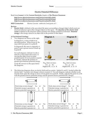
  • 1. Electric Circuits Name: Electric Potential Difference Read from Lesson 1 of the Current Electricity chapter at The Physics Classroom: http://www.physicsclassroom.com/Class/circuits/u9l1a.html http://www.physicsclassroom.com/Class/circuits/u9l1b.html http://www.physicsclassroom.com/Class/circuits/u9l1c.html MOP Connection: Electric Circuits: sublevels 2 and parts of 3 Review: 1. Electric field is defined as the aura about the space surrounding a charged object which exerts an electrical influence upon other charged objects in that space. The direction of the electric field vector is defined as the direction which a positive test charge would be accelerated. Potential energy is the energy stored in an object due to the position of that object. A Gravitational Analogy: 2. Two diagrams are shown at the right. In diagram A, a mass is held at an elevated position. When let go of, the mass falls from point A to point B. In diagram B, the mass is originally at point A and a person moves it back up to point B. For each diagram, indicate if work is done by a non-conservative force in moving the object from its initial position (point A) to its position at point B. Finally, indicate the position of greatest gravitational potential energy. Wnc done on mass: Wnc done on mass: Circle the answers in the space below the diagrams. Yes or No Yes or No Highest PE: A or B Highest PE: A or B 3. The following diagrams show an electric field and two points - labeled A and B - located within the electric field. A positive test charge is shown at point A. For each diagram, indicate whether work must be done upon the charge to move it from point A to point B. Finally, indicate the point (A or B) with the greatest electric potential energy and the greatest electric potential (PE/charge). Work done on test charge? Yes or No Work done on test charge? Yes or No Potential energy is greatest at: A B Potential energy is greatest at: A B Electric potential is greatest at: A B Electric potential is greatest at: A B Work done on test charge? Yes or No Work done on test charge? Yes or No Potential energy is greatest at: A B Potential energy is greatest at: A B Electric potential is greatest at: A B Electric potential is greatest at: A B © The Physics Classroom, 2009 Page 1
  • 2. Electric Circuits 3. When work is done on a positive test charge to move it from one location to another, potential energy _________ (increases, decreases) and electric potential _________ (increases, decreases). When a positive test charge naturally moves from one location to another (without the exertion of a non-conservative force), potential energy _________ (increases, decreases) and electric potential _________ (increases, decreases). 4. The diagram at the right shows a light bulb connected to a 12-V car battery. The + and - terminals are shown. a. As a + charge moves through the battery from D to A, it ________ (gains, loses) potential energy and ________ (gains, loses) electric potential. The point of highest energy within a battery is the ______ (+, - ) terminal. b. As a + charge moves through the external circuit from A to D, it ________ (gains, loses) potential energy and ________ (gains, loses) electric potential. The point of highest energy within the external circuit is closest to the ______ ( +, - ) terminal. c. Use >, <, and = signs to compare the electric potential (V) at the four points of the circuit. VA VB VC VD 5. The role of a battery in an electrical circuits can be described in three different ways. First, it is the energy supply. Second, the energy supplied by the battery is required to do work upon the charge to move it against the electric field from the negative terminal to the positive terminal. And third, by moving the charge against the field from negative to positive terminal, the battery establishes an electric potential difference across the two ends of the external circuit. Without a potential difference between two locations, charge will not move. When there is an electric potential between two locations, charge will move from the location of high potential to the location of low potential. The amount of potential difference (ΔV) between two locations is related to the work done in moving an amount of charge (Q) from the low potential to the high potential location. Work ΔV = Vhigh - Vlow = Q a. It takes _____ J of work to move 1 C of charge from the - to the + terminal of a 1.5-volt battery. b. It takes _____ J of work to move 2 C of charge from the - to the + terminal of a 12-volt battery. c. It takes 18 J of work to move _____ C of charge from the - to the + terminal of a 12-volt battery. ! d. It takes 12 J of work to move 2 C of charge from the - to the + terminal of a _____-volt battery. e. It takes _____ J of work to move _____ C of charge from the - to the + terminal of a 12-volt battery. 6. In the battery, energy is supplied to the charge to move it from low potential (- terminal) to high potential (+ terminal). Once at the + terminal, the charge spontaneously moves through the external circuit, losing energy as it passes through each electrical device. The electric potential which is gained by the charge when it passes through the battery is lost by the charge as it moves through the external circuit. These gains and losses in electric potential are often represented using an electric potential diagram. For the circuit at the right, complete the electric potential diagram, showing the relative potential of locations A, B, C, D, E, and F. © The Physics Classroom, 2009 Page 2
  • 3. Electric Circuits Name: Electric Circuits and Electric Current Read from Lesson 2 of the Current Electricity chapter at The Physics Classroom: http://www.physicsclassroom.com/Class/circuits/u9l2b.html http://www.physicsclassroom.com/Class/circuits/u9l2c.html http://www.physicsclassroom.com/Class/circuits/u9l2e.html MOP Connection: Electric Circuits: sublevel 1 1. To maintain a charge flow in an electric circuit, at least two requirements must be met: #1: An external energy supply (e.g., battery, wall outlet, generator, etc.) to pump the charge through the internal circuit and establish a potential difference across the circuit. #2: The external circuit must make up a "closed conducting loop" between the + and - terminal. Utilize your understanding of these requirements to state whether charge would flow through the following circuits. If there is no charge flow, then explain why not. Charge Flow: Yes or No? Charge Flow: Yes or No? Explanation: Explanation: Charge Flow: Yes or No? Charge Flow: Yes or No? Explanation: Explanation: Charge flow in a circuit is often compared to water flow. For water to flow between two points, there must be a difference in water pressure between the points. Water pressure is like electric potential. Water will only flow through a pipe if there is a difference in potential between the two ends. Charge will only flow through a wire if there is an electric potential difference across its ends. © The Physics Classroom, 2009 Page 3
  • 4. Electric Circuits 2. Consider the two requirements for an electric circuit (described in question #1). When a light bulb is burned out and no longer works, requirement #______ is not met. When a battery no longer works, requirement #______ is not met. 3. What do you believe? Respond to the following statements as being TRUE or FALSE. a. When a battery no longer works, it is out of charge and must be re-charged T or F before it can be used again. b. A battery can be a source of charge in a circuit. The charge which flows T or F through the circuit originates in the battery. c. Charge becomes used up as it flows through a circuit. The amount of charge T or F which exits a light bulb is less than the amount which enters the light bulb. d. Charge flows through circuits at very high speeds. This explains why the T or F light bulb turns on immediately after the wall switch is flipped. e. Commonwealth Edison supplies millions and millions of electrons to our T or F homes everyday. 4. A current is said to exist whenever _____. a. a wire is charged b. a battery is present c. electric charges are unbalanced d. electric charges move in a loop 5. As a quantity, electric current is defined as the _____. a. amount of charge present in a circuit b. potential energy per charge c. rate at which charge moves through a cross-sectional area of a wire d. speed at which charge moves from one location to another location 6. Complete the statements: a. A current of one ampere is a flow of charge at the rate of _______ coulomb per second. b. When a charge of 8 C flows past any point along a circuit in 2 seconds, the current is ________ A. c. If 5 C of charge flow past point A (diagram at right) in 10 seconds, then the current is _________ A. d. If the current at point D is 2.0 A, then _______ C of charge flow past point D in 10 seconds. e. If 12 C of charge flow past point A in 3 seconds, then 8 C of charge will flow past point E in ________ seconds. f. TRUE or FALSE: The current at point E is considerably less than the current at point A since charge is being used up in the light bulbs. 7. Which sentence best describes what happens to charge as it moves through an electric circuit? a. Charge is consumed or used up. b. Charge is re-energized and recycled. 8. Which sentence best describes how fast charge moves through an electric circuit? a. Charge moves very fast; faster than any human can run. b. Charge moves very slow; slower than the proverbial snail. 9. When you turn on the room lights, they light immediately. This is best explained by the fact that ____. a. electrons move very fast from the switch to the light bulb filament. b. electrons present everywhere in the circuit move instantly. © The Physics Classroom, 2009 Page 4
  • 5. Electric Circuits Name: Electrical Resistance Read from Lesson 3 of the Current Electricity chapter at The Physics Classroom: http://www.physicsclassroom.com/Class/circuits/u9l3a.html http://www.physicsclassroom.com/Class/circuits/u9l3b.html http://www.physicsclassroom.com/Class/circuits/u9l3c.html MOP Connection: Electric Circuits: sublevels 4 and 5 Physics Idea: As charge flows through an electric circuit, it encounters resistance. Resistance is a measure of the amount of hindrance to the flow of charge. 1. The cause of resistance to the flow of charge within an electrical wire is _____. a. mobile charge carriers collide with atoms of the resistor b. mobile charge carriers have mass (possess inertia) which resists their motion c. the electric field which causes charge flow diminishes with distance d. charge is consumed or used up as it flows through the wire 2. Resistance is quantifiable - that is, it can be measured and calculated. The standard metric unit used to express the amount of electrical resistance is the ____. a. Joule b. Watt c. Volt d. Amp e. Ohm 3. For the following pairs of wire descriptions, choose the wire which has the greatest resistance. Resistance to charge flow will be greatest in … . (Circle the best answer.) a. … a wire which is thin … a wire which is thick b. … a wire which is long … a wire which is short c. … a wire which is made of copper … a wire which is made of plastic d. … a wire which is made of copper … a wire which is made of silver 4. The rate at which charge flows through a circuit is ___________ to the resistance. a. inversely related b. directly related c. not related 5. For the following pairs of circuit descriptions, choose the circuit which has the greatest current. Given that all other factors are equal, the current will be greatest in a circuit which has … . a. … a high resistance … a low resistance b. … wires which are long … wires which are short c. … wires which are wide … wires which are thin d. … 12-gauge wires (1/12 inch diameter) … 14-gauge wires (1/14th inch diameter) th e. … copper wiring … silver wiring 6. Resistance is not the only variable which effects the current in an electric circuit. The current is also effected by the electric potential difference (Δ V) impressed across its ends. The electric potential difference is simply the battery voltage. As the battery voltage is increased (by swapping in higher voltage batteries), the current is _____________________ (increased, decreased). The relationship between electric potential difference (ΔV), resistance (R) and current (I) is given be the equation. "V I= R This equation, sometimes referred to as the Ohm's law equation, is often written as ΔV = I•R. Like all equations in physics, it can be used as a recipe for problem-solving and an equation to guide one's thinking about how an alteration in one ! variable effects another variable. © The Physics Classroom, 2009 Page 5
  • 6. Electric Circuits 7. A circuit is set up such that it has a current of 8.0 amps. What would be the new current if …. a. … the resistance (R) is increased by a factor of 2? b. … the resistance (R) is increased by a factor of 4? c. … the resistance (R) is decreased by a factor of 3? d. … the battery voltage (Δ V) is increased by a factor of 3? e. … the battery voltage (ΔV) is decreased by a factor of 2? f. … the resistance (R) is increased by a factor of 2 and the battery voltage (ΔV) is decreased by a factor of 2? g. … the resistance (R) is decreased by a factor of 4 and the battery voltage (ΔV) is increased by a factor of 3? 8. Express your understanding of the use of the I = ΔV / R equation by filling in the following blanks. a. An electrical device with a resistance of 2.0 Ω has an electric potential difference of 6.0 V impressed across it; the current in the device is _____ amperes. b. An electrical device with a resistance of 3.0 Ω has an electric potential difference of ______ V impressed across it; the current in the device is 4.0 amperes. c. An electrical device with a resistance of _____ Ω has an electric potential difference of 120 V impressed across it; the current in the device is 6.0 amperes. 9. Resistors are electrical devices designed to have a specific resistance. They are inserted in circuits to modify the actual current flowing through the circuit. When diagramming a circuit, a resistor is represented by the symbol . Which of the resistors in the two circuits (A or B) has the greatest resistance? Calculate the value. 10. Use arrows to show the direction of conventional current flow through the following circuits and use the I = ΔV / R equation to fill in the blanks. The three new circuit symbols introduced in the above diagrams are Power Supply Voltmeter (for measuring ΔV) Ammeter (for measuring I) © The Physics Classroom, 2009 Page 6
  • 7. Electric Circuits Name: Electrical Power and Energy Read from Lessons 2 and 3 of the Current Electricity chapter at The Physics Classroom: http://www.physicsclassroom.com/Class/circuits/u9l2d.html http://www.physicsclassroom.com/Class/circuits/u9l3d.html MOP Connection: Electric Circuits: sublevel 3 Review: 1. The electric potential at a given location in a circuit is the amount of _____________ per ___________ at that location. The location of highest potential within a circuit is at the _______ ( +, - ) terminal of the battery. As charge moves through the external circuit from the ______ ( +, - ) to the ______ ( +, - ) terminal, the charge loses potential energy. As charge moves through the battery, it gains potential energy. The difference in electric potential between any two locations within the circuit is known as the electric potential difference; it is sometimes called the _____________________ and represented by the symbol ______. The rate at which charge moves past any point along the circuit is known as the ___________________ and is expressed with the unit ________________. The diagram at the right depicts an electric circuit in a car. The rear defroster is connected to the 12-Volt car battery. Several points are labeled along the circuit. Use this diagram for questions #2-#6. 2. Charge flowing through this circuit possesses 0 J of potential energy at point ___. 3. The overall effect of this circuit is to convert ____ energy into ____ energy. a. electrical, chemical b. chemical, mechanical c. thermal, electrical d. chemical, thermal 4. The potential energy of the charge at point A is ___ the potential energy at B. a. greater than b. less than c. approximately equal to 5. The + charge gains potential energy as it moves between points ___ and ___. a. A and B b. B and C c. C and D d. D and A e. none of these 6. The + charge loses potential energy as it moves between points ___ and ___. a. A and B b. B and C c. C and D d. D and A e. none of these 7. The rate at which energy is delivered to a circuit by the energy source or the rate at which energy is consumed by an electrical device is known as the electric ______. a. current b. potential c. voltage d. power 8. The unit of electric power is the _____. a. Ampere b. Volt c. Watt d. Joule 9. Mechanical power (discussed in a previous unit) is the rate at which work is done on an object. Electrical power is the rate at which work is done on a charge (by the battery) or on an electrical device (by the charge). In terms of an equation, it is … . (Fill in the numerator and the denominator.) a. A 60-Watt light bulb uses up ____________ J of energy when left on for _____ 1 hour (3600 s). b. A 60-Watt light bulb uses up ____________ J of energy when left on for _____ 4 hours. c. A 1500-Watt hair dryer uses up ____________ J of energy when used for _____ 5 min (300 s). d. A 120-Watt fan uses up ____________ J of energy when left on for _____ a day. © The Physics Classroom, 2009 Page 7
  • 8. Electric Circuits 10. Substitution of other electrical equations ( I = Q/t and ΔV = I•R and ΔV = W/Q ) into the power equation yields the following three equations. P = I•ΔV P = I2•R P = ΔV2 / R Use these equations to solve the following problems. a. Calculate the resistance of a toaster oven if its power is 800 W when connected to a 110-V outlet. b. Calculate the resistance of the 1000 W microwave oven which gets plugged into to a 110-V outlet. c. The TI-84 calculator uses four 1.5-V batteries and has a power of 0.0008 W. What is the current? 11. The following two circuits consist of a power supply, an ammeter (for measuring current), and a light bulb. Use >, <, and = symbols to compare the electric potential at A to B and at C to D. Indicate whether the devices add energy to or remove energy from the charge. Finally, fill in all blanks. VA ____ VB (>, <, or =) VC ____ VD (>, <, or =) VB ____ VD (>, <, or =) 12. TRUE or FALSE: A kilowatt-hour is a unit of power. 13. Alfredo deDarke often leaves household appliances on for no good reason (at least according to his parents). The deDarke family pays 10¢/kilowatt-hour (i.e., $.15/kW•hr) for their electrical energy. Express your understanding of dollar power by filling in the following table. Power Rating Time Energy Used Costs (Watt) (hrs) (kilowatt-hour) ($) 60 Watt Bulb 1 0.060 kW•hr $0.009 60 Watt Bulb 4 Ten 60 Watt Bulb 24 60 Watt Bulb $10 7 Watt Night Light 168 7 Watt Night Light 7760 14. People often claim that an electrical appliance "uses up electricity." Explain what is actually being "used up" and what becomes of this thing which is being used up. © The Physics Classroom, 2009 Page 8
  • 9. Electric Circuits Name: Mathematical Relationships in Circuits Read from Lessons 2 and 3 of the Current Electricity chapter at The Physics Classroom: http://www.physicsclassroom.com/Class/circuits/u9l2c.html http://www.physicsclassroom.com/Class/circuits/u9l2d.html http://www.physicsclassroom.com/Class/circuits/u9l3c.html http://www.physicsclassroom.com/Class/circuits/u9l3d.html MOP Connection: Electric Circuits: sublevels 5 and 6 1. Matching: Identify the units on the following electrical quantities by placing a letter in the blank. The unit of charge is the ____. Choices: A. Coulombs The unit of electric potential is the ____. B. Amperes The unit of power is the ____. C. Volts The unit of potential energy is the ____. D. Ohms The unit of current is the ____. E. Joules The unit of resistance is the ____. F. Watts 2. An electric potential diagram is a useful means of representing the potential of a positive charge as it moves around a circuit. The electric potential of a charge at strategic locations in a circuit is represented on a chart. Points on the circuit where the charge has the highest potential are located highest on the chart; points of lowest potential are located lowest on the charts. At some points on the circuit, charges have approximately the same amount of potential. Construct electric potential diagrams for the following circuits. Label the points. a. b. 3. Given the circuit at the right with the listed current and resistance values, determine the electric potential at the indicated positions. Note that you are to find the electric potential (or voltage) and NOT the electric potential difference (or voltage drop). VA = V VB = V VC = V VD = V VE = V 4. Determine the following quantities for the circuit in question #3 above. PSYW a. The overall power. b. The power of the 6-ohm light bulb. c. The overall resistance. d. The energy used by the circuit in 10 minutes. © The Physics Classroom, 2009 Page 9
  • 10. Electric Circuits Show your work for the following problems. 5. a. Determine the amount of energy used when listening to your 5.0-Watt IPod Nano for 10 hours. b. Determine the resistance of the IPod if it uses a 5.2 Volt battery. c. What quantity of charge passes through the IPod battery during this 10-hr time period? 6. a. Calculate the energy used and current drawn by a 200-W window fan when plugged into a 110-V outlet and left on for an 8-hr time period. b. Calculate the energy used and the current drawn by a 3400-W air conditioner which is wired to a 220-V circuit and left on for an 8-hr time period. 7. A 2000-W hand dryer in a public bathroom at a zoo runs for 30 seconds per cycle. At a cost of 13 cents per kW•hr, determine the cost of running the dryer 200 times in a day. What is the annual cost of the hand dryer assuming it is used on average 200 times per day? Calculate the resistance and the current for the hand dryer if it is connected to a 220-V circuit. © The Physics Classroom, 2009 Page 10
  • 11. Electric Circuits Name: Series Circuits Read from Lesson 4 of the Current Electricity chapter at The Physics Classroom: http://www.physicsclassroom.com/Class/circuits/u9l4a.html http://www.physicsclassroom.com/Class/circuits/u9l4b.html MOP Connection: Electric Circuits: sublevels 7, 9 and 11 1. Electrical devices in circuits can be connected to each other in a number of different ways. The two most common connections are series connections and parallel connections. Observe the electrical wiring below. Indicate whether the connections are series or parallel. Series or Parallel? Series or Parallel? 2. Two electric circuits are diagrammed below. For each circuit, indicate which two devices are connected in series and which two devices are connected in parallel. Series Series Parallel Parallel 3. Comparing Series vs. Parallel Circuits Fill in the table below to indicate the manner in which series and parallel circuits differ. Series Circuit Parallel Circuit a. Definition: The pathway by which charge loops around the circuit is characterized by __________ pathway. b. Observation: If one light bulb goes out, the other light bulbs _________. c. Observation: As the number of resistors is increased, the overall current ______. d. Observation: As the number of resistors is increased, the overall resistance ______. © The Physics Classroom, 2009 Page 11
  • 12. Electric Circuits 4. The following diagrams represent circuits consisting of two electrical devices connected in series. For each diagram, fill in the blanks to show the voltage drop across the designated device. 5. Consider the following two diagrams of series circuits. For each diagram, use arrows to indicate the direction of the conventional current. Then, make comparisons of the voltage and the current at the designated points for each diagram. VA _____ VG VA _____ VF (>,<, or =) (>,<, or =) VB _____ VC VB _____ VC (>,<, or =) (>,<, or =) VB _____ VF VD _____ VF (>,<, or =) (>,<, or =) IA _____ IG IA _____ IF (>,<, or =) (>,<, or =) 5. Express your understanding of equivalent resistance by filling in the blanks. Having two 4-Ω resistors in series is equivalent to having one _____-Ω resistor. Having three 4-Ω resistors in series is equivalent to having one _____-Ω resistor. Having four 4-Ω resistors in series is equivalent to having one _____-Ω resistor. 6. TRUE or FALSE: Three light bulbs are connected in series. The filament of one of the light bulbs burns out. The remaining two light bulbs will still be lit; yet, their brightness will be noticeably less. © The Physics Classroom, 2009 Page 12
  • 13. Electric Circuits Name: 7. Analyze the following circuit and determine the equivalent or total resistance. Then determine the current at the ammeter location. Rtot = Rtot = I= I= 8. For the following diagrams, utilize the concept of equivalent resistance and Ohm's Law in order to fill in the blank. © The Physics Classroom, 2009 Page 13
  • 14. Electric Circuits 9. Compare circuits X and Y. Consider circuits X and Y below. Each circuit is powered by the same battery and contains identical resistors. Circuit X has one resistor and circuit Y has two resistors. The equivalent resistance of circuit X will be __________ (> or < or =) that of circuit Y. The current in the battery in X will be __________ (> or < or =) that in the battery in Y. 10. Three identical light bulbs are connected to a battery as shown below. Which adjustments could be made to the circuit that would increase the current being measured at X? Circle all that apply. a. Increase the resistance of one of the bulbs. b. Decrease the resistance of two of the bulbs. c. Increase the resistance of two of the bulbs. d. Decrease the voltage of the battery. e. Increase the voltage of the battery. f. Remove one of the bulbs. 11. Three identical light bulbs are connected to a battery as shown below. W, X,Y and Z represent locations along the circuit. Which one of the following statements is true? a. The potential difference between X and Y is greater than that between Y and Z. b. The potential difference between X and Y is greater than that between Y and W. c. The potential difference between Y and Z is greater than that between Y and W. d. The potential difference between X and Z is greater than that between Z and W. e. The potential difference between X and W is greater than that across the battery. f. The potential difference between X and Y is greater than that between Z and W. 12. Three identical light bulbs are connected to a battery as shown below. Which one of the following statements is true? a. All three bulbs will have the same brightness. b. The bulb between X and Y will be the brightest. c. The bulb between Y and Z will be the brightest. d. The bulb between Z and the battery will be the brightest. Justify your answer to this question using the language of physics. 13. Compare a circuit with three light bulbs to a circuit with two light bulbs. All light bulbs are identical. In which circuit will the overall power be the greatest? Intelligently defend your answer. © The Physics Classroom, 2009 Page 14
  • 15. Electric Circuits Name: Parallel Circuits Read from Lesson 4 of the Current Electricity chapter at The Physics Classroom: http://www.physicsclassroom.com/Class/circuits/u9l4a.html http://www.physicsclassroom.com/Class/circuits/u9l4c.html MOP Connection: Electric Circuits: sublevels 8, 10 and 11 Review: 1. A circuit in which all charge follows a single pathway is a ____ circuit; a circuit in which charge follows multiple pathways is a ____ circuit. a. series, parallel b. parallel, series 2. For a parallel circuit: as the number of resistors being used within the same parallel circuit increases, the overall resistance value _____________________________ (increases, decreases) and the overall current value _____________________________ (increases, decreases). 3. Household circuits are connected in parallel so that _____. Select all that apply. a. houses get the same effect with less current and thus save on energy costs. b. the turning off of one appliance does not result in the shut down of others. c. the hazard of electrocution and overheating of circuits is avoided. Water Analogy: 4. When the water flow (or charge flow) is divided into two or more separate pathways (as in a parallel circuit) the sum of the current in each individual pathway equals the total current. Utilize this principle to fill in the blanks in the following two diagrams. The meters in the diagram are measuring water flow rates in gallons per minute ("gpm"). 5. Apply the same principle to fill in the blanks in the following diagrams for charge flow (i.e., current) through a parallel circuit. © The Physics Classroom, 2009 Page 15
  • 16. Electric Circuits The Staircase Analogy Electric charge dividing into multiple pathways in a parallel circuit is analogous to people walking down stairs which divide up into separate paths. Imagine being at a large shopping mall; you are descending a rather wide stairway when all of a sudden it breaks up into several smaller stairways. Being in a hurry, you scan the different pathways down the stairs to see which path is least crowded. You finally decide that the left stairway is least crowded and make a "dash" towards it. You know that your "flow rate" will be greatest along the stairway with the least resistance. When the "people flow" divides up into multiple pathways, each pathway has the same change in height (or same gravitational potential drop); yet, the pathway which offers the least resistance will have the greatest flow rate. In an analogous manner, as charge flow divides up into multiple pathways in a parallel circuit, each pathway has the same electric potential drop; yet, the pathway with the least resistance will have the greatest rate of charge flow (i.e., current). 6. In the following circuits, fill in the blanks to indicate the current through the different pathways. Calculate the resistance of each resistor. Then rank the resistance of the resistors (labeled A, B, and C) in order from smallest to largest. Ranking of Resistance Ranking of Resistance ____ < ____ < ____ ____ < ____ < ____ 7. A three-resistor parallel circuit is created. The resistance of the resistors are 3 Ω, 6 Ω, and 9 Ω. Suppose that one observes the current through the 3 Ω resistor to be 6 Amperes. The voltage drop across this 3 Ω resistor must be _______ V. This provides sufficient evidence to conclude that the voltage drop across the 6 Ω resistor is _______ V and the voltage drop across the 9 Ω resistor is _________ V. Therefore, the current in the 6 Ω resistor is ________ Amperes and the current in the 9 Ω resistor is _________ Amperes. When these three branch currents combine, one would observe that the current in the ___________ V battery is _________ Amperes. In summary: R1 = 3 Ω R2 = 6 Ω R3 = 9 Ω I1 = 6 Amps I2 = _____ Amps I1 = _____ Amps ΔV1 = _____ V ΔV2 = _____ V ΔV3 = _____ V Ibattery = _____ Amps ΔVbattery = _____ V ΔVbattery / Ibattery = ________ 8. Consider the circuit at the right. a. There is a voltage drop of _____V across each 2-Ω resistor. b. By Ohm's law, the current in each 2-Ω resistor is _____ amps. c. The current through the battery is ______ amps. d. The resistors in parallel offer a combined resistance of _______ Ω to the charge being pumped by the battery. © The Physics Classroom, 2009 Page 16
  • 17. Electric Circuits Name: Equivalent Resistance Devices connected in parallel offer a resistance to the flow of charge through the circuit. The total resistance (or equivalent resistance) is related to the resistance of the individual devices which are connected in parallel. The equivalent resistance can be determined with the equation 1 1 1 1 Requivalent = R1 + R2 + R3 The electric potential difference across each branch is the product of the equivalent resistance and the total current (outside the branches). Use the diagram below at the right in order to answer questions #9-#13. PSYW 9. Determine the equivalent resistance of the circuit at the right. 10. Determine the overall current in the circuit (as determined at position A or H). 11. Determine the electric potential difference (i.e. voltage drop) across the 5-Ω resistor (from B to C). 12. Determine the current through the 5-Ω resistor (from B to C). 13. Determine the current through the 7-Ω resistor (from B to C). 14. TRUE or FALSE: If resistors are connected in parallel, then the electric potential difference (i.e., voltage drop) will be greatest across the resistor with the greatest resistance. 14. TRUE or FALSE: If resistors are connected in parallel, then the current will be the same through each resistor. 15. A 2-Ω and a 4-Ω resistor are connected in a parallel circuit. The electric potential difference (i.e., voltage drop) across the 4-Ω resistor will be ___ the electric potential difference across the 2-Ω resistor. a. two-times more than b. two times less than c. the same size as 16. A 2-Ω and a 4-Ω resistor are connected in a parallel circuit. The current through the 4-Ω resistor will be ___ the current through the 2-Ω resistor. a. two-times more than b. two times less than c. the same size as © The Physics Classroom, 2009 Page 17
  • 18. Electric Circuits 17. For each of the following branched systems, determine the equivalent resistance. a. b. is equivalent to is equivalent to _______ Ω _______ Ω c. d. is equivalent to is equivalent to _______ Ω _______ Ω e. f. is equivalent to is equivalent to _______ Ω _______ Ω g. h. is equivalent to is equivalent to _______ Ω _______ Ω i. j. is equivalent to is equivalent to _______ Ω _______ Ω k. l. is equivalent to is equivalent to _______ Ω _______ Ω 18. Four resistors are connected in a parallel circuit. Three of the resistance values are known - 3 Ω, 4 Ω and 6 Ω. The overall or equivalent resistance of the four resistors must be ____ Ω. (Choose the one answer which is most informative.) a. greater than 3 b. greater than 6 c. greater than 13 d. less than 13 e. less than 3 f. ... it is impossible to tell. © The Physics Classroom, 2009 Page 18
  • 19. Electric Circuits Name: Combination Circuits Read from Lesson 4 of the Current Electricity chapter at The Physics Classroom: http://www.physicsclassroom.com/Class/circuits/u9l4d.html MOP Connection: Electric Circuits: sublevel 12 1. Review: Determine the equivalent resistance for the following sets of resistors. 2. The circuits below are known as combination or compound circuits; they are composed of resistors which are arranged both in parallel with each other as well as other resistors arranged in series with each other. In each circuit, the resistors which are arranged in parallel have the same resistance value. For each combination circuit shown below, determine the equivalent resistance for the combination of three resistors, the total current (i.e., at the battery), and the current at each of the three indicated locations. Req = Req = Itot = Itot = Req = Req = Itot = Itot = © The Physics Classroom, 2009 Page 19
  • 20. Electric Circuits Circuit Analysis Read from Lesson 4 of the Current Electricity chapter at The Physics Classroom: http://www.physicsclassroom.com/Class/circuits/u9l4b.html http://www.physicsclassroom.com/Class/circuits/u9l4c.html http://www.physicsclassroom.com/Class/circuits/u9l4d.html MOP Connection: Electric Circuits: sublevel 11 1. Fill in the blanks in the following diagram. Show appropriate units. RTot= ITot = ∆V1= I1 ∆V2= I2 ∆V3= I3 VTot = 60 V R1 = 12.5 Ω R2 = 14.7 Ω R3 = 19.1 Ω 2. Fill in the blanks in the following diagram. Show appropriate units. RTot= ITot = ∆V1= I1 ∆V2= I2 ∆V3= I3 VTot = 60 V R1 = 12.5 Ω R2 = 14.7 Ω R3 = 19.1 Ω 3. Fill in the blanks in the following diagram. Show appropriate units. RTot= ITot = ∆V1= I1 ∆V2= I2 ∆V3= I3 VTot = 120 V R1 = 16.0 Ω R2 = 16.0 Ω R3=6.0 Ω © The Physics Classroom, 2009 Page 20