CAO_Basic_Structure_of_computer_ppt
•Descargar como PPT, PDF•
0 recomendaciones•1,314 vistas


Recomendados
Más contenido relacionado
La actualidad más candente
La actualidad más candente (20)
Similar a CAO_Basic_Structure_of_computer_ppt
Similar a CAO_Basic_Structure_of_computer_ppt (20)
Último
Último (20)
CAO_Basic_Structure_of_computer_ppt
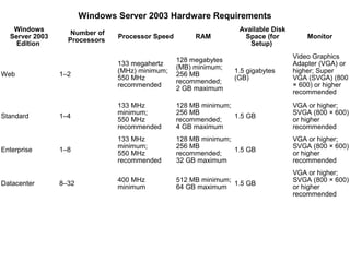
- 1. Windows Server 2003 Hardware Requirements Windows Available Disk Number of Server 2003 Processor Speed RAM Space (for Monitor Processors Edition Setup) Video Graphics 128 megabytes 133 megahertz Adapter (VGA) or (MB) minimum; (MHz) minimum; 1.5 gigabytes higher; Super Web 1–2 256 MB 550 MHz (GB) VGA (SVGA) (800 recommended; recommended × 600) or higher 2 GB maximum recommended 133 MHz 128 MB minimum; VGA or higher; minimum; 256 MB SVGA (800 × 600) Standard 1–4 1.5 GB 550 MHz recommended; or higher recommended 4 GB maximum recommended 133 MHz 128 MB minimum; VGA or higher; minimum; 256 MB SVGA (800 × 600) Enterprise 1–8 1.5 GB 550 MHz recommended; or higher recommended 32 GB maximum recommended VGA or higher; 400 MHz 512 MB minimum; SVGA (800 × 600) Datacenter 8–32 1.5 GB minimum 64 GB maximum or higher recommended
- 2. Windows XP Professional Hardware Requirements Recommended Minimum Requirements Requirements Intel Pentium (or Intel Pentium II (or compatible) 233 MHz or compatible) 300 MHz or higher processor higher processor 128 MB (4 GB maximum) of 64 MB of RAM RAM 2 GB hard disk with 650 MB of free disk space (additional disk space 2 GB of free disk space required if installing over a network) VGA or higher video SVGA video adapter and adapter Plug and Play monitor
- 3. Architecture & Organization Architecture is those attributes visible to the programmer Instruction set, number of bits used for data representation, I/O mechanisms, addressing techniques. e.g. Is there a multiply instruction? Organization is how features are implemented Control signals, interfaces, memory technology. e.g. Is there a hardware multiply unit or is it done by repeated addition?
- 4. Chapter 1. Basic Structure of Computers
- 5. Function Computer functions: Data processing Data storage Data movement Control
- 6. Functional view Functional view of a computer Data Storage Facility Data Control Moveme Mechanism nt Apparatu s Data Processing Facility
- 7. Operations (1) Data movement e.g. keyboard to screen Data Storage Facility Data Control Moveme Mechanism nt Apparatu s Data Processing Facility
- 8. Operations (2) Storage e.g. Internet download to disk Data Storage Facility Data Control Moveme Mechanism nt Apparatu s Data Processing Facility
- 9. Operation (3) Processing from/to storage e.g. updating bank statement Data Storage Facility Data Control Moveme Mechanism nt Apparatu s Data Processing Facility
- 10. Operation (4) Processing from storage to I/O e.g. printing a bank statement Data Storage Facility Data Control Moveme Mechanism nt Apparatu s Data Processing Facility
- 11. Structure - Top Level Peripherals Computer Central Main Processing Memory Unit Computer Systems Interconnection Input Output Communication lines
- 12. Structure - The CPU CPU Computer Arithmetic Registers and I/O Login Unit System CPU Bus Internal CPU Memory Interconnection Control Unit
- 13. Functional Units Arithmetic Input and logic Memory Output Control I/O Processor Figure 1.1. Basic functional units of a computer.
- 14. Information Handled by a Computer Machine instructions Govern the transfer of information within a computer between the computer and its I/O devices Specify the arithmetic and logic operations to be performed Forms Program Data Used as operands by the instructions Source program Encoded in binary code – 0 and 1
- 15. Memory Unit Store programs and data Two classes of storage Primary storage Fast Programs must be stored in memory while they are being executed Large number of semiconductor storage cells Processed in words Address RAM and memory access time Memory hierarchy – cache, main memory Secondary storage – larger and cheaper
- 16. Arithmetic and Logic Unit (ALU) Most computer operations are executed in ALU of the processor. Load the operands into memory – bring them to the processor – perform operation in ALU – store the result back to memory or retain in the processor. Registers ALU – Faster than other devices
- 17. Control Unit All computer operations are controlled by the control unit. The timing signals that govern the I/O transfers are also generated by the control unit. Control unit is usually distributed throughout the machine instead of standing alone. Operations of a computer: Accept information in the form of programs and data through an input unit and store it in the memory Fetch the information stored in the memory, under program control, into an ALU, where the information is processed Output the processed information through an output unit Control all activities inside the machine through a control unit
- 18. Basic Operational Concepts
- 19. Review Activity in a computer is governed by instructions. To perform a task, an appropriate program consisting of a list of instructions is stored in the memory. Individual instructions are brought from the memory into the processor, which executes the specified operations. Data to be used as operands are also stored in the memory.
- 20. A Typical Instruction Add LOCA, R0 or Load r2,LOCB or Store R4,LOC Add the operand at memory location LOCA to the operand in a register R0 in the processor. Place the sum into register R0. The original contents of LOCA are preserved. The original contents of R0 is overwritten. Instruction is fetched from the memory into the processor – the operand at LOCA is fetched and added to the contents of R0 – the resulting sum is stored in register R0.
- 21. Separate Memory Access and ALU Operation Load LOCA, R1 : R1 <= m[LOCA] (lhs to rhs) Load R1, LOCA : R1 <= m[LOCA] (rhs to lhs) Add R1, R0 : R0<= R0+R1 (lhs to rhs) Add R1, R0 : R0<= R0+R1 (rhs to lhs) Whose contents will be overwritten? Add R4, R2, R3
- 22. How does execution take place? Cell (Prison) Way to cell Ready Room Jail Superintendent Inspector Constable 0 Constable 1 Judicial Rep Execution Constable n1
- 23. Connection Between the Processor and the Memory Memory MAR MDR Control PC R 0 R 1 Processor IR ALU R n 1 n general purpose registers Figure 1.2. Connections between the processor and the memory.
- 24. Registers Instruction register (IR) Program counter (PC) General- purpose register (R0 – Rn-1)
- 25. Typical Operating Steps Programs reside in the memory through input devices PC is set to point to the first instruction The contents of PC are transferred to MAR A Read signal is sent to the memory The first instruction is read out and loaded into MDR The contents of MDR are transferred to IR Decode and execute the instruction
- 26. Typical Operating Steps (Cont’) Get operands for ALU General-purpose register Memory (address to MAR – Read – MDR to ALU) Perform operation in ALU Store the result back To general-purpose register To memory (address to MAR, result to MDR – Write) During the execution, PC is incremented to the next instruction
- 27. Interrupt Normal execution of programs may be preempted if some device requires urgent servicing. The normal execution of the current program must be interrupted – the device raises an interrupt signal. Interrupt-service routine Current system information backup and restore (PC, general-purpose registers, control information, specific information)
- 28. Software Printer Disk OS Program t0 t1 t2 t3 t4 t5 Processor Timeline
- 29. Chapter 2. Machine Instructions and Programs
- 30. Objectives Machine instructions and program execution, including branching and subroutine call and return operations. Number representation and addition/subtraction in the 2’s-complement system. Addressing methods for accessing register and memory operands. Assembly language for representing machine instructions, data, and programs. Program-controlled Input/Output operations.
- 31. Number, Arithmetic Operations, and Characters
- 33. Sign and Magnitude Representation -7 +0 -6 1111 0000 +1 1110 0001 -5 +2 + 1101 0010 -4 1100 0011 +3 0 100 = + 4 -3 1011 0100 +4 1 100 = - 4 1010 0101 -2 +5 - 1001 0110 -1 1000 0111 +6 -0 +7 High order bit is sign: 0 = positive (or zero), 1 = negative Three low order bits is the magnitude: 0 (000) thru 7 (111) Number range for n bits = +/-2n-1 -1 Two representations for 0
- 34. One’s Complement Representation -0 +0 -1 1111 0000 +1 1110 0001 -2 +2 + 1101 0010 -3 1100 0011 +3 0 100 = + 4 -4 1011 0100 +4 1 011 = - 4 1010 0101 -5 +5 - 1001 0110 -6 1000 0111 +6 -7 +7 Subtraction implemented by addition & 1's complement Still two representations of 0! This causes some problems Some complexities in addition
- 35. One’s Complement Representation Steps for subtracting x from y with an n-bit 1's complement representation. • Negate x using 1's complement. • Reverse all the bits in x to form -x. • Add -x and y. • If the sum exceeds n bits, add the extra bit to the result. • If the sum does not exceed n bits, leave the result as it is (Ans is in 1’s complement negative value).
- 36. 0001 (1) - 0111 - (7) 2.Next, we convert 01112 to its negative 0001 (1) + 1000 +(-7) equivalent and add this to 00012. 1001 (?) 3.This time our results does not cause an overflow, so we do not need to adjust the sum. Notice that our final answer is a 0001 (1) negative number since it begins with a 1. + 1000 +(-7) Remember that our answer is in 1's 1001 (-6) complement notation so the correct decimal value for our answer is -610 and not 910.
- 37. Two’s Complement Representation -1 +0 -2 1111 0000 +1 1110 0001 -3 +2 + 1101 0010 like 1's comp except shifted -4 1100 0011 +3 0 100 = + 4 one position clockwise -5 1011 0100 +4 1 100 = - 4 1010 0101 -6 +5 - 1001 0110 -7 1000 0111 +6 -8 +7 Only one representation for 0 One more negative number than positive number
- 38. Steps for subtracting x from y with an n-bit 2's complement representation. 1.Negate x using 2's complement. a. Reverse all the bits in x. b. Add 1 to form -x. 2.Add -x and y. 3.Discard any bits greater than n.
- 39. Binary, Signed-Integer Representations B V alues represented Sign and b3 b2b1b0 magnitude 1' s complement 2' s complement 0 1 1 1 +7 +7 + 7 0 1 1 0 +6 +6 + 6 0 1 0 1 +5 +5 + 5 0 1 0 0 +4 +4 + 4 0 0 1 1 +3 +3 + 3 0 0 1 0 +2 +2 + 2 0 0 0 1 +1 +1 + 1 0 0 0 0 +0 +0 + 0 1 0 0 0 - 0 -7 - 8 1 0 0 1 - 1 -6 - 7 1 0 1 0 - 2 -5 - 6 1 0 1 1 - 3 -4 - 5 1 1 0 0 - 4 -3 - 4 1 1 0 1 - 5 -2 - 3 1 1 1 0 - 6 - 1 - 2 1 1 1 1 - 7 -0 - 1 Figure 2.1. Binary, signed-integer representations.
- 40. Addition and Subtraction – 2’s Complement 4 0100 -4 1100 +3 0011 + (-3) 1101 If carry-in to the high order bit = 7 0111 -7 11001 carry-out then ignore carry if carry-in differs from 4 0100 -4 1100 carry-out then overflow -3 1101 +3 0011 1 10001 -1 1111 Simpler addition scheme makes twos complement the most common choice for integer number systems within digital systems
- 41. RULES – Addition and Subtraction of n bit signed numbers using 2’s Complement 1: to add two numbers, add their n-bit representations, ignoring the carry out signal from MSB position 2: to subtract two numbers X and Y, form the 2’s complement of Y and then add it to X as per rule 1 -- The result will be in 2’s complement representation in both cases -- Negative numbers are always represented in 2’s complement
- 42. 2’s-Complement Add and Subtract Operations (a) 0010 ( + 2) (b) 0100 ( + 4) + 0011 ( + 3) + 1010 (- 6) 0101 ( + 5) 1110 (- 2) (c) 1011 (- 5) (d) 0111 ( + 7) + 1110 (- 2) + 1101 ( - 3) 1001 (- 7) 0100 ( + 4) (e) 1101 (- 3) 1101 - 1001 (- 7) + 0111 0100 ( + 4) (f) 0010 ( + 2) 0010 - 0100 ( + 4) + 1100 1110 ( - 2) (g) 0110 ( + 6) 0110 - 0011 ( + 3) + 1101 0011 ( + 3) (h) 1001 ( - 7) 1001 - 1011 (- 5) + 0101 1110 ( - 2) (i) 1001 (- 7) 1001 - 0001 ( + 1) + 1111 1000 ( - 8) (j) 0010 ( + 2) 0010 - 1101 ( - 3) + 0011 0101 ( + 5) Figure 2.4. 2's-complement Add and Subtract operations.
- 43. Overflow Conditions 0111 1000 5 0101 -7 1001 3 0011 -2 1100 -8 1000 7 10111 Overflow Overflow 0000 1111 5 0101 -3 1101 2 0010 -5 1011 7 0111 -8 11000 No overflow No overflow
- 44. Overflow - Add two positive numbers to get a negative number or two negative numbers to get a positive number OVERFLOW: when carry-in to the high-order bit does not equal carry out OVERFLOW: Sign of two summands same but the sign of the result is different NO OVERFLOW: Sign of all the three are same (X and Y and Result)
- 45. Sign Extension Task: Given w-bit signed integer x Convert it to w+k-bit integer with same value Rule: Make k copies of sign bit: X ′ = xw–1 ,…, xw–1 , xw–1 , xw–2 ,…, x0 w X • • • k copies of MSB • • • X′ • • • • • • k w
- 46. Sign Extension Example short int x = 15213; int ix = (int) x; short int y = -15213; int iy = (int) y; Decimal Hex Binary x 15213 3B 6D 00111011 01101101 ix 15213 00 00 C4 92 00000000 00000000 00111011 01101101 y -15213 C4 93 11000100 10010011 iy -15213 FF FF C4 93 11111111 11111111 11000100 10010011 Characters: represented using 8 bits – ASCII Codes
- 47. Memory Locations, Addresses, and Operations
- 48. Memory Location, Addresses, and Operation n bits first word Memory consists second word of many millions of storage cells, • each of which can • • store 1 bit. Data is usually i th word accessed in n-bit groups called • “WORD”. n is • • called word length. last word Figure 2.5. Memory words.
- 49. Memory Location, Addresses, and Operation 32-bit word length example 32 bits b 31 b 30 b1 b0 • • • Sign bit: b 31= 0 for positive numbers b 31= 1 for negative numbers (a) A signed integer 8 bits 8 bits 8 bits 8 bits ASCII ASCII ASCII ASCII character character character character (b) Four characters
- 50. Memory Location, Addresses, and Operation To retrieve information from memory, either for one word or one byte (8-bit), addresses for each location are needed. A “k-bit” address can access 2k memory locations/Bytes, namely 0 – 2k-1, called memory space. 24-bit memory: 224 = 16,777,216 = 16M (1M=220) 32-bit memory: 232 = 4G (1G=230) 1K(kilo)=210 1T(tera)=240
- 51. Memory Location, Addresses, and Operation It is impractical to assign distinct addresses to individual bit locations in the memory. The most practical
- 52. Big-Endian and Little-Endian Assignments Big-Endian: lower byte addresses are used for the most significant bytes of the word Little-Endian: opposite ordering. lower byte addresses are used for the less significant bytes of the word Word address Byte address Byte address 0 0 1 2 3 0 3 2 1 0 4 4 5 6 7 4 7 6 5 4 • • • • • • k k k k k k k k k k 2 -4 2 -4 2 -3 2- 2 2 - 1 2 - 4 2- 1 2 - 2 2 -3 2 -4 (a) Big-endian assignment (b) Little-endian assignment Figure 2.7. Byte and word addressing.
- 53. Memory Location, Addresses, and Operation Address ordering of bytes Word alignment Words are said to be “aligned” in memory if they begin at a byte addr. that is a multiple of the num of bytes in a word. 16-bit word: word addresses: 0, 2, 4,…. 32-bit word: word addresses: 0, 4, 8,…. 64-bit word: word addresses: 0, 8,16,…. Access numbers, characters, and character strings (Special Control char)
- 54. Memory Operation Load (or Read or Fetch) Copy the content. The memory content doesn’t change. Address – Load Registers can be used Store (or Write) Overwrite the content in memory Address and Data – Store Registers can be used
- 55. Instruction and Instruction Sequencing
- 57. Register Transfer Notation Identify a location by a symbolic name standing for its hardware binary address (LOC, R0,…) Contents of a location are denoted by placing square brackets around the name of the location (R1←[LOC], R3 ←[R1]+[R2]) Register Transfer Notation (RTN)
- 58. Assembly Language Notation Represent machine instructions and programs. Move LOC, R1 = R1←[LOC] Add R1, R2, R3 = R3 ←[R1]+[R2]
- 59. Basic Instruction Formats Three-Address Instructions ADD R1, R2, R3 R3 ← R1 + R2 Two-Address Instructions ADD R1, R2 R2 ← R1 + R2 One-Address Instructions ADD AR AC ← AC + M[AR] Zero-Address Instructions ADD TOS ← TOS + (TOS – 1) Opcode Operand(s) or Address(es)
- 60. Instruction Formats Example: Evaluate (A+B) ∗ (C+D) Three-Address 1. ADD A, B, R1 ; R1 ← M[A] + M[B] 2. ADD C, D ,R2 ; R2 ← M[C] + M[D] 3. MUL R1, R2, X ; M[X] ← R1 ∗ R2
- 61. Instruction Formats Example: Evaluate (A+B) ∗ (C+D) Two-Address 1. MOV A, R1 ; R1 ← M[A] 2. ADD B,R1 ; R1 ← R1 + M[B] 3. MOV C, R2 ; R2 ← M[C] 4. ADD D, R2 ; R2 ← R2 + M[D] 5. MUL R2, R1 ; R1 ← R1 ∗ R2 6. MOV R1,X ; M[X] ← R1
- 62. Instruction Formats Example: Evaluate X = (A+B) ∗ (C+D) One-Address 1. LOAD A ; AC ← M[A] 2. ADD B ; AC ← AC + M[B] 3. STORE T ; M[T] ← AC 4. LOAD C ; AC ← M[C] 5. ADD D ; AC ← AC + M[D] 6. MUL T ; AC ← AC ∗ M[T] 7. STORE X ; M[X] ← AC
- 63. Using Registers Registers are faster Shorter instructions The number of registers is smaller (e.g. 32 registers need 5 bits) Potential speedup Minimize the frequency with which data is
- 64. Instruction Execution and Straight-Line Sequencing Address Contents i Assumptions: Begin execution here Move A,R0 i +4 3-instruction program - One memory operand Add B,R0 segment per instruction i +8 Move R0,C - 32-bit word length - Memory is byte addressable A - Full memory address can be directly specified in a single-word instruction B Data for the program Two-phase procedure -Instruction fetch -Instruction execute C Page 43 Figure 2.8. A program for C ← [Α] + [Β].
- 65. i Move NUM1,R0 i+4 Add NUM2,R0 Branching i+8 Add NUM3,R0 • • • i + 4n - 4 Add NUMn,R0 i + 4n Move R0,SUM • • • SUM NUM1 NUM2 • • • NUMn Figure 2.9. A straight-line program for adding n numbers.
- 66. Move N,R1 Clear R0 Branching LOOP Determine address of "Next" number and add Program "Next" number to R0 loop Decrement R1 Branch>0 LOOP Branch target Move R0,SUM Conditional branch • • • SUM N n NUM1 Figure 2.10. Using a loop to add n numbers. NUM2 • • • NUMn
- 68. Conditional Branch Instructions Example: A: 11110000 A: 1 1 1 1 0 0 0 0 +(−B): 1 1 1 0 1 1 0 0 B: 0 0 0 1 0 1 0 0 11011100 A - B C=1 Z=0 S=1 V=0
- 69. Status Bits Cn-1 A B Cn ALU F V Z S C Fn-1 Zero Check
- 70. Addressing Modes
- 71. Generating Memory Addresses How to specify the address of branch target? Can we give the memory operand address directly in a single Add instruction in the loop? Use a register to hold the address of NUM1; then increment by 4 on each pass through the loop.
- 72. Addressing Modes Opcode Mode ... Implied AC is implied in “ADD M[LOC]” in “One-Address” instruction. TOS is implied in “ADD” in “Zero-Address” instruction. Immediate The use of a constant in MOV #5,R1 i.e. R1 ← 5 MOV #LOC, R1 i.e Addr of LOC is moved to R1
- 73. Addressing Modes Register-Indicate which register holds the operand Auto increment / Auto decrement Access & update in 1 instruction. Direct/ Absolute Address Use the given address to access a memory location eg: loc, num in instruction
- 74. Addressing Modes Indirect Address Indicate the memory location/ Register that holds the address of the memory location that holds the data R1/LOC = 101 100 101 0 1 0 4 102 103 104 1 1 0 A
- 75. Addressing Modes Relative Address 0 EA = PC + Offset 1 Offset = -100 L 2 Could be Positive + or Negative (2’s Complement) 100 PC = 103 101 102 Branch>0 L 103 104
- 76. Addressing Modes Indexed EA = Index (X) + Relative Addr (Ri) Useful with X=2 “Autoincrement” or “Autodecrement” + 100 Ri = 100 101 Could be Positive or Negative 102 1 1 0 A (2’s Complement) 103 104
- 77. Addressing Modes Base Register EA = Base Register + Relative Addr (Ri) Could be Positive Ri = 2 or Negative (2’s Complement) + 100 0 0 0 5 BR = 100 101 0 0 1 2 102 0 0 0 A Usually points 103 0 1 0 7 to the beginning 104 0 0 5 9 of an array
- 78. Addressing Modes Name Assem bler syn tax Addressing function The different ways in which Immediate #Value Op erand = Value the location of an operand is Register Ri EA = Ri specified in Absolute (Direct) LOC EA = LOC an instruction are referred to Indirect (Ri ) EA = [Ri ] as addressing (LOC) EA = [LOC] modes. Index X(R i) EA = [Ri ] + X Basewith index (Ri ,Rj ) EA = [Ri ] + [Rj ] Basewith index X(R i,Rj ) EA = [Ri ] + [Rj ] + X and offset Relative X(PC) EA = [PC] + X Autoincrement (Ri )+ EA = [Ri ] ; Increment Ri Autodecrement − (Ri ) Decrement Ri ; EA = [Ri]
- 79. Indexing and Arrays Index mode – the effective address of the operand is generated by adding a constant value to the contents of a register. Index register - Ri X(Ri): EA = X + [Ri] The constant X may be given either as an explicit number or as a symbolic name representing a numerical value.
- 80. Indexing and Arrays In general, the Index mode facilitates access to an operand whose location is defined relative to a reference point within the data structure in which the operand appears. Several variations: Base with Index (Ri, Rj): EA = [Ri] + [Rj] Base with Index and Offset X(Ri, Rj): EA = X + [Ri] + [Rj]
- 81. Relative Addressing Relative mode – the effective address is determined by the Index mode using the program counter in place of the general-purpose register. X(PC) – note that X is a signed number Branch>0 LOOP This location is computed by specifying it as an offset from the current value of PC. Branch target may be either before or after the branch instruction, the offset is given as a signed num.
- 82. Additional Modes Autoincrement mode – the effective address of the operand is the contents of a register specified in the instruction. After accessing the operand, the contents of this register are automatically incremented to point to the next item in a list. (Ri)+. The increment is 1 for byte-sized operands, 2 for 16-bit operands, and 4 for 32-bit operands. Autodecrement mode: -(Ri) – decrement first Move N,R1 Move #NUM1,R2 Initialization Clear R0 LOOP Add (R2)+,R0 Decrement R1 Branch>0 LOOP Move R0,SUM Figure 2.16. The Autoincrement addressing mode used in the program of Figure 2.12.
- 84. Types of Instructions Data Transfer Instructions Name Mnemonic Data value is Load LD not modified Store ST Move MOV Exchange XCH Input IN Output OUT Push PUSH Pop POP
- 85. Data Transfer Instructions Mode Assembly Register Transfer Direct address LD ADR AC ← M[ADR] Indirect address LD @ADR AC ← M[M[ADR]] Relative address LD $ADR AC ← M[PC+ADR] Immediate operand LD #NBR AC ← NBR Index addressing LD ADR(X) AC ← M[ADR+X] Register LD R1 AC ← R1 Register indirect LD (R1) AC ← M[R1] Autoincrement LD (R1)+ AC ← M[R1], R1 ← R1+1 AutoDecrement LD -(R1) R1 ← R1-1,AC ← M[R1]
- 86. Data Manipulation Instructions Arithmetic Name Mnemonic Increment INC Logical & Bit Manipulation Decrement DEC Add ADD Shift Subtract SUB Multiply MUL Divide DIV Name Mnemonic Add with carry ADDC Clear CLR Subtract with borrow SUBB Complement COM Negate NEG Name Mnemonic AND AND Logical shift right SHR OR OR Logical shift left SHL Exclusive-OR XOR Arithmetic shift right SHRA Clear carry CLRC Arithmetic shift left SHLA Set carry SETC Rotate right ROR Complement Rotate left ROL COMC carry Rotate right through Enable interrupt EI RORC carry
- 87. Program Control Instructions Name Mnemonic Branch BR Jump JMP Skip SKP Subtract A – B but Call CALL don’t store the result Return RET Compare CMP (Subtract) 10110001 Test (AND) TST 00001000 Mask 00000000
- 88. Conditional Branch Instructions Mnemonic Branch Condition Tested Condition BZ Branch if zero Z = 1 BNZ Branch if not zero Z = 0 BC Branch if carry C = 1 BNC Branch if no carry C = 0 BP Branch if plus S = 0 BM Branch if minus S = 1 BV Branch if overflow V = 1 BNV Branch if no overflow V = 0
- 89. Assembler Directives ? How to interpret names in the program ? Where to place the instructions in the memory ? Where to place the data operands in the memory ORIGIN 200 Label Op Operand(s) Comment SUM DATAWORD 000 N EQU 100 NLST RESERVE 400 ORIGIN 100 START MOVE N,R1 MOVE #NUM1,R2 CLR R0 LOOP ADD (R2),R0 ADD #4,R2 DEC R1 BGTZ LOOP MOVE R0,SUM RETURN END START
- 90. Number Notation ADD #93,R1 (decimal) ADD #$5D,R1 (hexadecimal) ADD #%01011101,R1 (binary)
- 92. LOGICAL INSTRUCTIONS Logical operations: AND, OR, NOT NOT destination (change from 0’s to 1’s and 1’s to 0’s) How to get two’s complement of a number? R0 = “AZCD” Find if ‘Z’ is present in “AZCD” as 3rd char?????
- 93. Logical Shifts Logical shift – shifting left (LShiftL) and shifting right (LShiftR) C R0 0 before: 0 0 1 1 1 0 . . . 0 1 1 after: 1 1 1 0 . . . 0 1 1 0 0 (a) Logical shift left LShiftL #2,R0 0 R0 C before: 0 1 1 1 0 . . . 0 1 1 0 after: 0 0 0 1 1 1 0 . . . 0 1 (b) Logical shift rght i LShiftR #2,R0
- 94. Arithmetic Shifts Sign bit value is maintained….. R0 C before: 1 0 0 1 1 . . . 0 1 0 0 after: 1 1 1 0 0 1 1 . . . 0 1 (c) Arithmetic shift rght i AShiftR #2,R0
- 95. C R0 before: 0 1 1 1 0 . . . 0 1 1 Rotate 0 after: 1 1 1 0 . . . 0 1 1 0 1 (a) Rotate left without carr y RotateL #2,R0 C R0 before: 0 0 1 1 1 0 . . . 0 1 1 after: 1 1 1 0 . . . 0 1 1 0 0 (b) Rotate left with carr y RotateLC #2,R0 R0 C before: 0 1 1 1 0 . . . 0 1 1 0 after: 1 1 0 1 1 1 0 . . . 0 1 (c) Rotate r ight without carr y RotateR #2,R0 R0 C before: 0 1 1 1 0 . . . 0 1 1 0 after: 1 0 0 1 1 1 0 . . . 0 1 (d) Rotate r ight with carr y RotateRC #2,R0 Figure 2.32. Rotate instructions.
- 96. Multiplication and Division •Multiply Ri, Rj Rj <- [Ri] x [Rj] Ri, Rj -n bit Signed Integers • Product can be large as 2n bits • Lower order half of the product is placed in Rj and Higher order in R(j+1) •Divide Ri,Rj Rj<- [Ri] / [Rj] Ri, Rj -n bit Signed Integers •Quotient in Rj and Remainder in R(j+1)
- 97. Stacks
- 98. Stack Organization Current Top of Stack LIFO TOS 0 Last In First Out 1 2 3 4 5 SP 6 0 1 2 3 7 0 0 5 5 FULL EMPTY 8 0 0 0 8 9 0 0 2 5 Stack Bottom 10 0 0 1 5 Stack
- 99. Stack Organization Current 1 6 9 0 Top of Stack PUSH TOS 0 SP ← SP – 1 1 M[SP] ← DR 2 3 If (SP = 0) then (FULL ← 1) 4 EMPTY ← 0 5 1 6 9 0 SP 6 0 1 2 3 7 0 0 5 5 FULL EMPTY 8 0 0 0 8 9 0 0 2 5 Stack Bottom 10 0 0 1 5 Stack
- 100. Stack Organization Current Top of Stack POP TOS 0 DR ← M[SP] 1 SP ← SP + 1 2 3 If (SP = 11) then (EMPTY ← 1) 4 FULL ← 0 5 1 6 9 0 SP 6 0 1 2 3 7 0 0 5 5 FULL EMPTY 8 0 0 0 8 9 0 0 2 5 Stack Bottom 10 0 0 1 5 Stack
- 101. Stack Routines Push Operation: Subtract #4, SP Move NEWITEM, (SP) Pop Operation: Move (SP), ITEM Add #4, SP Routines with boundary checking: SAFEPUSH Compare #1500, SP Branch<= STACKFULL Move NEWITEM, -(SP) SAFEPOP Compare #2000, SP Branch>0 STACKEMPTY Move (SP)+, ITEM
- 102. Subroutines: Call Instruction is used to branch to a subroutine which performs following operations: •Store the contents of the PC in the Link Register •Branch to the target address specified in the instruction Return Instruction in the Subroutine •Branch to the address in the Link Register Mem Loc Calling Pgm Mem Loc Subroutine SUB 200 Call SUB 1000 1st Instruction 204 nxt Instruction … … Return 1000 PC 204 Link 204 Call Return
- 103. Subroutines Nesting and Processor Stack: • Subroutine Nesting: one Subroutine call another • Single link register – Problem (Contents overwritten) • Return address are generated and used in LIFO • Processor Stack is used to maintain these return addresses • Stack pointer Register (SP) is used to point to Processor Stack • Call Instruction – Pushes the contents of PC to Processor Stack • Return Instruction – Pops the return address from the stack to the PC
- 104. Subroutines – Parameter Passing: Calling Program Move N, R1 Move #num1, R2 Call LISTADD Move R0,SUM …… Subroutine LISTADD Clear R0 LOOP Add (R2)+, R0 Decrement R1 Branch > 0 LOOP Return
- 105. Subroutines – The Stack Frame: SP (Stack ptr) ---- Saved [R1] Saved [R0] LocalVar3 LocalVar3 LocalVar3 Stack Frame FP (Frame Ptr) --- Saved [FP] For Called Return Address Sub Routine Param 1 Param 2 Param 3 <-Old TOS Frame Ptr (FP): Ptr to access the parameters passed to the Subroutine and local variables used by the Subroutine
- 106. The Stack Frame for Nested SR: Mem Loc Instructions Main Program 2000 Move PARAM2, -(SP) 2004 Move PARAM1, -(SP) 2008 Call SUB1 2012 Move (SP), Result 2016 Add #8, SP Param3 2020 Next Instruction…….. [R3] from Main 1st Subroutine [R2] from Main 2100 SUB1 Move FP,-(SP) 2104 Move SP,FP [R1] from Main 2108 MoveMultiple R0-R3, -(SP) [R0] from Main 2112 Move 8(FP),R0 Stack 2116 Move 12(SP), R1 Frame FP-> [FP] from Main for …….. 1st SR Move PARAM3, -(SP) 2010 (RA ) 2160 Call SUB2 2164 Move (SP)+, R2 Param2 ….. Param1 Move R3, 8(FP) MoveMultiple (SP)+, R0 – R3 <-Old TOS Move (SP)+, FP Return
- 107. The Stack Frame for Nested SR: Mem Loc Instructions 1st Subroutine 2100 SUB1 Move FP,-(SP) [R0] from SUB1 2104 Move SP,FP 2108 MoveMultiple R0-R3, -(SP) FP-> [FP] from SUB1 Stack 2112 Move 8(FP),R0 2164 Frame 2116 Move 12(SP), R1 for …….. 2nd SR Param3 Move PARAM3, -(SP) 2160 Call SUB2 [R3] from Main 2164 Move (SP)+, R2 ….. [R2] from Main Move R3, 8(FP) MoveMultiple (SP)+, R0 – R3 [R1] from Main Move (SP)+, FP [R0] from Main Return Stack Frame FP-> [FP] from Main for 2nd Subroutine 1st SR 3100 SUB2 Move FP,-(SP) 2010 (RA ) 3104 Move SP,FP 3108 MoveMultiple R0-R1, -(SP) Param2 3112 Move 8(FP),R0 Param1 …… Move R1, 8(FP) <-Old TOS MoveMultiple (SP)+, R0 – R1 Move (SP)+, FP Return
- 108. Reverse Polish Notation Infix Notation A + B Prefix or Polish Notation + A B Postfix or Reverse Polish Notation (RPN) A B + (2) (4) ∗ (3) (3) ∗ RPN + A∗ B+C∗ D AB∗ CD∗ + (8) (3) (3) ∗ + (8) (9) + 17
- 109. Reverse Polish Notation Example (A + B) ∗ [C ∗ (D + E) + F] (A B +) (D E +) C F+∗ ∗
- 110. Reverse Polish Notation Stack Operation (3) (4) ∗ (5) (6) ∗ + PUSH 3 PUSH 4 6 MULT PUSH 5 30 5 4 PUSH 6 3 42 12 MULT ADD
- 111. Encoding of Machine Instructions
- 112. Encoding of Machine Instructions Assembly language program needs to be converted into machine instructions. (ADD = 0100 in ARM instruction set) In the previous section, an assumption was made that all instructions are one word in length. OP code: the type of operation to be performed and the type of operands used may be specified using an encoded binary pattern Suppose 32-bit word length, 8-bit OP code (how many instructions can we have?), 16 registers in total (how many bits?), 3-bit addressing mode indicator. Add R1, R2 8 7(4+3) 7(4+3) 10 Move 24(R0), R5 OP code Source Dest Other info LshiftR #2, R0 Move #$3A, R1 Branch>0 LOOP (a) One-word instruction(Possible Format)
- 113. Encoding of Machine Instructions What happens if we want to specify a memory operand using the Absolute addressing mode? Move R2, LOC 14-bit for LOC – insufficient Solution – use two words OP code Source Dest Other info Memory address/Immediate operand (b) Two-word instruction Immediate Values: AND #$00FF0000, R2
- 114. Encoding of Machine Instructions Then what if an instruction in which two operands can be specified using the Absolute addressing mode? Move LOC1, LOC2 Solution – use two additional words This approach results in instructions of variable length. Complex instructions can be implemented, closely resembling operations in high-level programming languages – Complex Instruction Set Computer (CISC)
- 115. Encoding of Machine Instructions If we insist that all instructions must fit into a single 32-bit word, it is not possible to provide a 32-bit address or a 32-bit immediate operand within the instruction. It is still possible to define a highly functional instruction set, which makes extensive use of the processor registers. Add R1, R2 ----- yes Add LOC, R2 ----- no Add (R3), R2 ----- yes Reduced Instruction Set Computer (RISC)