
Recomendados
Más contenido relacionado
La actualidad más candente
La actualidad más candente (17)
Similar a EDI- 3 Installation for lift truck impact detection & reporting
Similar a EDI- 3 Installation for lift truck impact detection & reporting (20)
Más de tedjurca
Más de tedjurca (20)
Último
Último (20)
EDI- 3 Installation for lift truck impact detection & reporting
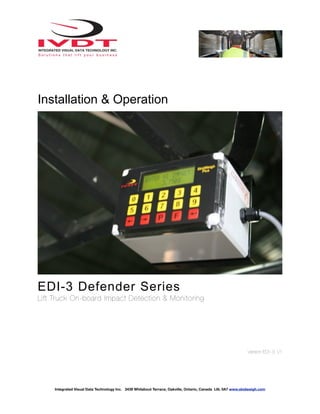
- 1. Installation & Operation EDI-3 Defender Series Lift Truck On-board Impact Detection & Monitoring Version:ED!- 3 V1 Integrated Visual Data Technology Inc. 3439 Whilabout Terrace, Oakville, Ontario, Canada L6L 0A7 www.skidweigh.com
- 2. General Installation Guide This EDI-3 installation & set up guide describes how to install the unit, input for low / high impact values and use of your lift truck on-board impact detection system. Following the instructions in this guide will enable you to get your system operating quickly and easily. In the event that you require additional assistance, please contact customer support via e- mail at support@skidweigh.com , visit www.skidweigh.com or contact us at the address or contact number below: Integrated Visual Data Technology Inc. 3439 Whilabout Terrace, Oakville, ON, Canada, L6L 0A7 Phone: 905-469-0985 Safety Always disconnect the vehicle battery while installing any of the Defender systems or any other electronic product. Route the cables where they will be protected. Use commonly accepted install practices for after market industrial vehicle electronic devices. The installation of the Defender systems should only be performed by an acknowledged lift truck dealer technician or end user electro and hydraulic technical installer. Here are two acceptable methods of making a wire connections: * Soldering your connections (recommended) * Crimp connectors (with the use of the proper crimping tool) Regardless of the method you choose, ensure that the connection is mechanically sound and properly insulated. Use high quality electrical tape and shrink tubing where necessary. This product is connected directly to the vehicle’s ignition switch, 12 to 55 V DC. There is no on-off switch on the unit. Electro-Magnetic Compatibility CE conformity to EC directive 89/336 (EMC) by application of harmonized standards: Interference stability EN 61000-6-2 and EN 61326-1 interference emit EN 61000-6-3, EN 61326-1 for the pressure transducer. EDI-3 Defender Series Our policy is one of continuous improvement and the information in this document is subject to change without notice. Check that software version displayed on LCD is the one applicable for your application. Overview of components The standard EDI-3 Defender system consist of digital indicator, wiring harness and mounting bracket Visual Warnings The standard EDI-3 Defender system shows actual G value in increments of 0.5G on LCD display. Integrated Visual Data Technology Inc. 3439 Whilabout Terrace, Oakville, Ontario, Canada L6L 0A7 www.skidweigh.com
- 3. Defender installation precautions Do not mount Defender indicator to the dashboard plastic surface. The installation on “soft” surface area will act as a shock absorber and system will not indicate a true impact values. Selecting the mounting location for Defender Mount defender indicator in front of the operator . The LCD display of the indicator must be positioned in direction of the forward travel direction of the vehicle. Digital indicator should be mounted on solid metal surface (dashboard, upper railing, side railing, etc.). Use Defender metal mounting bracket to fasten the system to the vehicle body. Unit should be installed in vertical position, +/- 15 degree is allowed for proper operation. Electrical Connections All stand alone Defender systems operate from 12 to 55 V DC. There are only two wires to be connected to the vehicle. RED Wire - Ignition switch Black Wire - Battery negative or vehicle ground Integrated Visual Data Technology Inc. 3439 Whilabout Terrace, Oakville, Ontario, Canada L6L 0A7 www.skidweigh.com
- 4. Defender automatic calibration function Defender systems are re-calibrated automatically every time power is turned on. Operation Depending on the model, standard Defender system does not reqiire any input from the lift truck operator. The LCD display will show time and date when ignition switch is turned on. There are two lift truck impact detection that will be shown to the operator. The first one is the “LOW impact”, which will be shown to the operator on LCD display. The second one is the “High impact” which will be shown on LCD display, audio alarm will be activated for 10 seconds and the event will be recorder on USB memory stick and / or send to Bolero wireless portal for further analysis. All “High impacts” events will be recorded on Bolero portal, e-mail notification can be send out, etc. All impact events are shown to the operator on LCD display in actual G forces. No Operator ID# Input Operator ID# Input ( Maximum 3 digits ) Operator Input ID# Enter valid operator ID# (Max. 3 digits) and press Enter key Optional USB Recordings Defender units equipped with USB port will record start and finish of the session (Ignition On and Off) and all of the “High impacts” events. Default values for “LOW” and “High” impact detections Factory default value for “LOW Impact” is 1G and for the “HIGH Impact” is 3G. Integrated Visual Data Technology Inc. 3439 Whilabout Terrace, Oakville, Ontario, Canada L6L 0A7 www.skidweigh.com
- 5. Default values for “LOW” and “High” impact detections can be changed by the end user Depending on your equipment type, lifting capacity and operational environment the end user can easily change factory default impact values for “LOW” and “High” impact events. It should be noted that “LOW” impact value of 1G is recommended for majority of operational facilities. It’s only a visual warning to the operator when vehicles are used in “rough” manner. How to change factory set impact values With the LCD display showing date and time, Press IVDT icon located on upper left side of the monitor) and LCD display will ask for the PASSWORD: For your system enter a following PASSWORD number: and LCD display will show ENTER LOW IMPACT 0.500g Press Left or Right arrow to set desired low impact value and than Press Enter Key. After pressing Enter Key the LCD display will advance to ENTER HI IMPACT 2.500g Press Left or Right arrow to set desired High impact value and than Press Enter Key. After pressing Enter Key the LCD display will go back to normal operational mode showing data and time. The new modified G set up is done and the new impact values are saved into the system. Integrated Visual Data Technology Inc. 3439 Whilabout Terrace, Oakville, Ontario, Canada L6L 0A7 www.skidweigh.com