SlideShare una empresa de Scribd logo
1 de 4
Descargar para leer sin conexión
Charles Moyes (cwm55) and Shentong Wang (sw477)                                                  Lab 5 Write-Up


NOTE: A YouTube video demo of our project can be viewed at www.youtube.com/watch?v=jYAYAhgnLdQ


Lab 5 Write-Up: MSP430 Microcontroller Craps Game
Project Overview
The idea was to implement a playable game of Craps (casino dice rolling game) using the MSP430 mi-
crocontroller board. External LEDs that were arranged in dice shaped format are used to show the
values of the dice rolls. A basic (yet detailed) description of the game rules can be found at http:
//en.wikipedia.org/wiki/Craps.
    A more thorough explanation can be found in the How To Play Craps section. Current limiting
resistors are connected across the LEDs and the digital I/O pins in series to ground. The push button is
used to trigger dice rolls. The Charlie-plexing LED multiplexing scheme is used to connect lots of LED’s to
the micro-controller without running out of pins. Red and green LED’s on the breadboard indicate whether
the “Pass” (green LED lit) or the “Don’t Pass” (red LED lit) betters win the round. The built-in green
and red LEDs on the MSP430 board indicate whether the round is in the “come out” or “point” stage. The
Craps embedded system acts as dice for each player in the game, and as such, is passed around the table to
each player who wishes to be a “shooter.”

How To Play Craps
Craps is an easy-to-learn betting game played with two dice. The players bet “pass” or “don’t pass” (whether
the dice roller will win or lose). The player who rolls the dice is designated the “shooter.” The shooter begins
rolling. If the first roll is a 2, 3 or 12, the shooter loses (“craps”) and the “don’t pass” betters win the round.
On the other hand, if the first roll is a 7 or 11 (a “natural”) then the shooter wins and the “pass” betters
win the round. If the first roll is any other number (the “point”), then the shooter continually rolls the dice
until that number is rolled again (win!) or the shooter rolls a seven (lose!). The first roll is the “come out”
roll, while all others afterwards are “point” rolls.
    Playing the game using the electronic device we designed is very easy. Simply press the push button on
the microcontroller and the dice roll will illuminate on the LEDs. If the dice roll wins, the green status LED
lights up and a happy song is played on the piezoelectric speaker. If the dice roll loses, then the red status
LED lights up and a sad song is played. If the round continues with another dice roll, then a chirp sound is
emitted, and the game waits for the player to press the push button again.

Game Logic Finite State Machine (FSM)
The game logic was easily represented by a finite state machine with several states, transitions, and variables
as shown in the following diagram:


                                                                                                                1
Charles Moyes (cwm55) and Shentong Wang (sw477)                                               Lab 5 Write-Up


    The game state variable stores 0 if the round is in the “come out” phase and 1 if the round is in the
“point” phase. The state led variable stores a 0 if nobody has won or lost, 1 if the shooter has won (pass),
and 2 if the shooter has lost (don’t pass). Lastly, the point variable stores the value of the point dice roll
that must be rolled again before a seven in order to win the round. Initially, state led = game state =
point = 0, and if an unknown state configuration comes up during gameplay, then the FSM resets to this
safe initial state.
    The “come out” states (for game state == 0) are a first-roll lose state, a first-roll win state, and a point
state that sets game state to 1 and advances onto the “point” round. The “point states” are a win state
(for rolling the point again), a lose state (for rolling a seven), and an anything else state that allows the
round to continue in the “point” game state. Transitions between these states are governed by the value of
the dice roll, the point, and the game state.

Pseudo-Random Number Generator
A pseudo-random number generator will be used to determine the values of the dice rolls in software. The
Linear Congruential Generator algorithm based on modular arithmetic was selected due to its “randomness”
and its ease of implementation:
                                       Xn+1 ≡ (aXn + c)(mod m)
where Xn is the sequence of values generated and m, a, c, and X0 (the so-called seed) are constants. Since
16-bit numbers are used, we chose values of m = 216 , a = 16, 807, and c = 33, where c and m are necessarily
relatively prime. Because the microcontroller board lacks a built-in real-time clock, an un-initialized garbage
value in memory is used instead to seed the random number generator (X0 ). Hardcoding a random number
generator seed into the code would make playing the game much less interesting since upon rebooting, all
games would have the same sequence of dice rolls and thus would not be random.

Project Construction
Project construction was accomplished using a breadboard and external electronic components that interface
with the digital I/O pins on the microcontroller breakout board. Bruce Land assisted us in soldering low-
profile headers onto the breakout board pins. From there, we wired a piezoelectric speaker across on of
the pins to the ground pin (pin 12). From reading its data sheet, we found that no limiting resistor was
necessary for the piezoelectric speaker. The LED’s were then wired to the board using a Charlie-plexing
LED multiplexing scheme described in the next section. Limiting resistors were calculated using Ohm’s Law
(180-220 Ohm resistors were used) for the specifications given in the LED data sheets. The overall allocation
and usage of I/O pins is shown in the following table:

 Break-out Board Pin         Microcontroller Pin                               Usage
          5                         P2.2                Pin 1 of Red Dice LED Charlie-plex Configuration
          6                         P2.3                Pin 3 of Red Dice LED Charlie-plex Configuration
          7                         P2.4                Pin 2 of Red Dice LED Charlie-plex Configuration
          8                         P4.3               Pin 1 of Yellow Dice LED Charlie-plex Configuration
          9                         P4.4               Pin 2 of Yellow Dice LED Charlie-plex Configuration
         10                         P4.5               Pin 3 of Yellow Dice LED Charlie-plex Configuration
         11                         P4.6                         Middle LED of Red Dice Display
         12                         GND                          Ground for Piezoelectric Speaker
         13                         P2.6                        Piezoelectric Speaker (+) Terminal
         14                         P2.7                        Middle LED of Green Dice Display
         15                        Unused                                        –
         16                        Unused                                        –
         17                         P3.0                          Green “Win/Pass” Status LED
         18                         P3.1                        Red “Lose/Don’t Pass” Status LED
   Note that break-out board pins 1-4 were inaccessible because the plastic enclosure of the USB programmer
dongle covered them up.


                                                                                                             2
Charles Moyes (cwm55) and Shentong Wang (sw477)                                               Lab 5 Write-Up


Charlie-plexing LEDs
This project uses 16 external LEDs, but there are a limited number of I/O pins available on the microcon-
troller breakout board. This technique allows n pins to drive up to 2 · n = n(n − 1) LED’s. Moreover, only
                                                                          2
n limiting resistors are needed. Each unique pair of I/O pins in the configuration supports two LED’s (one in
the forward direction and one in the reverse direction) in series. This pair is referred to as a “complementary
pair” and either LED in the pair can be lit by setting one I/O pin to Ground and the other to +5V. By
disconnecting all other I/O pins in the configuration, any one LED in any of the complementary pairs can
be selectively lit. Disconnecting an I/O pin can be accomplished by setting that pin to be an input pin using
the appropriate DIR register. This setting puts the pin in a high-impedance state. A schematic illustrating
the general idea follows:


    In our project, two Charlie-Plexed configurations of 6 LED’s (using three I/O pins each) are used for
the two dice displays. Moreover, the seventh center LED is connected to a separate I/O pin across ground
without any multiplexing scheme. Each I/O pin has a limiting resistor connected in series to it. The
complementary pairs are connected in parallel on the breadboard. In order to light multiple LED’s in one
dice display at a time, cycling is used where each simultaneously-lit LED is toggled on and off one-by-one at
a high refresh rate. If the refresh rate is high enough, this technique gives the illusion that multiple LED’s
are being lit at the same time.

Piezoelectric Speaker
A piezoelectric speaker is used to play audio feedback during the game. Musical note frequencies are deter-
mined from the equal-tempered scale (tabulated at http://www.phy.mtu.edu/~suits/notefreqs.html).
A look-up table of compiler-time definitions stores these frequencies. Pulse width modulation (PWM) is
used to send a 5V amplitude square wave to the piezoelectric speaker from a digital I/O pin. By varying
the frequency of the square wave signal, different pitches can be played from the speaker. Songs are simply
sequences of notes (of varying time durations) with periods of silence in between. Sequential code can be
written to play notes at specific frequencies for certain durations and to add silences in between notes. As
an example, the code to play the “game win” song follows:
// P l a y s a happy song t h a t t e l l s t h e p l a y e r t h a t t h e y won
void playWin ( )
{
            beep ( c , 3 5 0 ) ;
            beep ( e , 3 5 0 ) ;
            beep ( g , 3 5 0 ) ;
            beep ( cH , 5 0 0 ) ;
}


Code Overview
A brief overview of the code written in the C programming language for this project follows. Note that the
code is heavily documented using lots of comments. The main.c file contains an intro() function that does
a light-up demo where the “Imperial March” song is played from Star Wars on the piezoeletric speaker. The
main() function sets up the I/O pins, interrupts, and enters the game loop. The Port 1 interrupt handler
catches the push button interrupts.


                                                                                                             3
Charles Moyes (cwm55) and Shentong Wang (sw477)                                               Lab 5 Write-Up


    The speaker.c file contains piezoelectric speaker code. The beep function plays a tone at a specified
frequency on the speaker using digital PWM. The playGoAgain(), playLose(), playWin(), and play()
functions all play various songs on the speaker using beep and appropriately spaced delays. Note that
some of the code here (particularly beep and the Imperial March song code) was borrowed from http:
//processors.wiki.ti.com/index.php/Playing_The_Imperial_March.
    The util.c file contains code to delay the MSP430 using delay cycles and random(), a Linear
Congruential random number generator described in the earlier section.
    The leds.c file contains code to light specific LEDs in the red and yellow Charlieplex configurations
(lightLED() and lightLED2() functions respectively). The lightDiceNum() function is used to show a
particular dice face pattern (for a die value of 1-6) on one of the dice displays by cycling through the LEDs
in the configuration at a high refresh rate. The lightStatusLEDs() function controls the red and green
status LED’s on the board and on the microcontroller (for communicating game state information to the
player). Lastly, the displayDice() is a utility function lights up the two dice displays with a given dice roll
by calling lightDiceNum() with the appropriate parameters.
    The game.c file contains all of the game logic. The updateGameState() function implements the finite
state machine (FSM) described in an earlier section. This function encodes all of the game rules for Craps
and is heavily commented. The gameLoop() function updates the dice LED displays by cycling through them
once and then updates the status LED displays. It is continually invoked throughout program execution.
Lastly, the buttonPressHandler() push button handler invokes the game state FSM to update the game
state during a new dice roll. For more information about the code, feel free to look through it and read our
comments.

Conclusion/Photo/Demo Video
In conclusion, a fun and playable game was implemented using a microcontroller. The project was a rich and
worthwhile hands-on learning experience. We learned about Charlie-plexing, practiced soldering, assembled
a circuit using a breadboard, debugged a circuit using a multimeter, calculated appropriate resistances for
components such as LEDs, and got to plan, design, and create a tangible electronic gadget. Many hours of
work in the lab went into implementing and debugging this project, but the work was very fulfilling and the
end result was great!


                                                                                                             4

Más contenido relacionado

Destacado

Destacado (12)

Speaker Bracket
Speaker BracketSpeaker Bracket
Speaker Bracket
 
Gameplay specificationfinal
Gameplay specificationfinalGameplay specificationfinal
Gameplay specificationfinal
 
Clmkt copy - copy
Clmkt   copy - copyClmkt   copy - copy
Clmkt copy - copy
 
Ece4760 hw5
Ece4760 hw5Ece4760 hw5
Ece4760 hw5
 
Aws slide share-mockup v2
Aws slide share-mockup v2Aws slide share-mockup v2
Aws slide share-mockup v2
 
Cs665 writeup
Cs665 writeupCs665 writeup
Cs665 writeup
 
Car sim rendering
Car sim renderingCar sim rendering
Car sim rendering
 
Final report
Final reportFinal report
Final report
 
Alpha releasepresentation
Alpha releasepresentationAlpha releasepresentation
Alpha releasepresentation
 
Feliz cumple
Feliz cumpleFeliz cumple
Feliz cumple
 
Presentation slides
Presentation slidesPresentation slides
Presentation slides
 
Polysaccharide
PolysaccharidePolysaccharide
Polysaccharide
 

Similar a Ece3140 lab5 writeup

Ece lab5 proposal
Ece lab5 proposalEce lab5 proposal
Ece lab5 proposalChuck Moyes
 
Arduino Workshop
Arduino WorkshopArduino Workshop
Arduino Workshopatuline
 
LEDs and DIPs Switches
LEDs and DIPs SwitchesLEDs and DIPs Switches
LEDs and DIPs SwitchesBach Nguyen
 
Electronz_Chapter_2.pptx
Electronz_Chapter_2.pptxElectronz_Chapter_2.pptx
Electronz_Chapter_2.pptxMokete5
 
Lights off PROJECT REPORT
Lights off PROJECT REPORTLights off PROJECT REPORT
Lights off PROJECT REPORTMohit Lamba
 
Embedded system course projects - Arduino Course
Embedded system course projects - Arduino CourseEmbedded system course projects - Arduino Course
Embedded system course projects - Arduino CourseElaf A.Saeed
 
Pin diagram 8085 microprocessor(For College Seminars)
Pin diagram 8085 microprocessor(For College Seminars)Pin diagram 8085 microprocessor(For College Seminars)
Pin diagram 8085 microprocessor(For College Seminars)Naman Joshi
 
Arduino windows remote control
Arduino windows remote controlArduino windows remote control
Arduino windows remote controlVilayatAli5
 
Nand gate breadboardtask
Nand gate breadboardtaskNand gate breadboardtask
Nand gate breadboardtaskshankarganesh73
 
MCS51 Training board Model CATC2016A
MCS51 Training board Model CATC2016AMCS51 Training board Model CATC2016A
MCS51 Training board Model CATC2016AArkhom Jodtang
 
IOTC08 The Arduino Platform
IOTC08 The Arduino PlatformIOTC08 The Arduino Platform
IOTC08 The Arduino PlatformEoin Brazil
 

Similar a Ece3140 lab5 writeup (20)

Ece lab5 proposal
Ece lab5 proposalEce lab5 proposal
Ece lab5 proposal
 
Arduino Workshop
Arduino WorkshopArduino Workshop
Arduino Workshop
 
LEDs and DIPs Switches
LEDs and DIPs SwitchesLEDs and DIPs Switches
LEDs and DIPs Switches
 
Arduino based applications part 2
Arduino based applications part 2Arduino based applications part 2
Arduino based applications part 2
 
Electronz_Chapter_2.pptx
Electronz_Chapter_2.pptxElectronz_Chapter_2.pptx
Electronz_Chapter_2.pptx
 
snake game
snake gamesnake game
snake game
 
Est 6
Est 6Est 6
Est 6
 
Lights off PROJECT REPORT
Lights off PROJECT REPORTLights off PROJECT REPORT
Lights off PROJECT REPORT
 
Embedded system course projects - Arduino Course
Embedded system course projects - Arduino CourseEmbedded system course projects - Arduino Course
Embedded system course projects - Arduino Course
 
Hd44780a00 dtasheet
Hd44780a00 dtasheetHd44780a00 dtasheet
Hd44780a00 dtasheet
 
Day1
Day1Day1
Day1
 
Led fade
Led  fadeLed  fade
Led fade
 
Pin diagram 8085 microprocessor(For College Seminars)
Pin diagram 8085 microprocessor(For College Seminars)Pin diagram 8085 microprocessor(For College Seminars)
Pin diagram 8085 microprocessor(For College Seminars)
 
2th year iv sem de lab manual
2th year iv sem de lab manual2th year iv sem de lab manual
2th year iv sem de lab manual
 
Arduino windows remote control
Arduino windows remote controlArduino windows remote control
Arduino windows remote control
 
Nand gate breadboardtask
Nand gate breadboardtaskNand gate breadboardtask
Nand gate breadboardtask
 
Lab1
Lab1Lab1
Lab1
 
publish manual
publish manualpublish manual
publish manual
 
MCS51 Training board Model CATC2016A
MCS51 Training board Model CATC2016AMCS51 Training board Model CATC2016A
MCS51 Training board Model CATC2016A
 
IOTC08 The Arduino Platform
IOTC08 The Arduino PlatformIOTC08 The Arduino Platform
IOTC08 The Arduino Platform
 

Más de Chuck Moyes

Más de Chuck Moyes (8)

Concept documentfinal
Concept documentfinalConcept documentfinal
Concept documentfinal
 
Beta presentation
Beta presentationBeta presentation
Beta presentation
 
Manual small (1)
Manual small (1)Manual small (1)
Manual small (1)
 
Ece4760 progress report2
Ece4760 progress report2Ece4760 progress report2
Ece4760 progress report2
 
Ece4760 hw4
Ece4760 hw4Ece4760 hw4
Ece4760 hw4
 
Ece4760 progess report1
Ece4760 progess report1Ece4760 progess report1
Ece4760 progess report1
 
Fb graph
Fb graphFb graph
Fb graph
 
Ai plan
Ai planAi plan
Ai plan
 

Ece3140 lab5 writeup

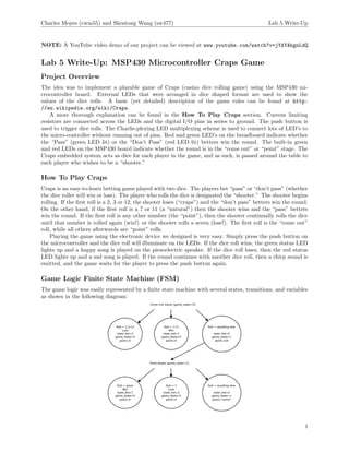
  • 1. Charles Moyes (cwm55) and Shentong Wang (sw477) Lab 5 Write-Up NOTE: A YouTube video demo of our project can be viewed at www.youtube.com/watch?v=jYAYAhgnLdQ Lab 5 Write-Up: MSP430 Microcontroller Craps Game Project Overview The idea was to implement a playable game of Craps (casino dice rolling game) using the MSP430 mi- crocontroller board. External LEDs that were arranged in dice shaped format are used to show the values of the dice rolls. A basic (yet detailed) description of the game rules can be found at http: //en.wikipedia.org/wiki/Craps. A more thorough explanation can be found in the How To Play Craps section. Current limiting resistors are connected across the LEDs and the digital I/O pins in series to ground. The push button is used to trigger dice rolls. The Charlie-plexing LED multiplexing scheme is used to connect lots of LED’s to the micro-controller without running out of pins. Red and green LED’s on the breadboard indicate whether the “Pass” (green LED lit) or the “Don’t Pass” (red LED lit) betters win the round. The built-in green and red LEDs on the MSP430 board indicate whether the round is in the “come out” or “point” stage. The Craps embedded system acts as dice for each player in the game, and as such, is passed around the table to each player who wishes to be a “shooter.” How To Play Craps Craps is an easy-to-learn betting game played with two dice. The players bet “pass” or “don’t pass” (whether the dice roller will win or lose). The player who rolls the dice is designated the “shooter.” The shooter begins rolling. If the first roll is a 2, 3 or 12, the shooter loses (“craps”) and the “don’t pass” betters win the round. On the other hand, if the first roll is a 7 or 11 (a “natural”) then the shooter wins and the “pass” betters win the round. If the first roll is any other number (the “point”), then the shooter continually rolls the dice until that number is rolled again (win!) or the shooter rolls a seven (lose!). The first roll is the “come out” roll, while all others afterwards are “point” rolls. Playing the game using the electronic device we designed is very easy. Simply press the push button on the microcontroller and the dice roll will illuminate on the LEDs. If the dice roll wins, the green status LED lights up and a happy song is played on the piezoelectric speaker. If the dice roll loses, then the red status LED lights up and a sad song is played. If the round continues with another dice roll, then a chirp sound is emitted, and the game waits for the player to press the push button again. Game Logic Finite State Machine (FSM) The game logic was easily represented by a finite state machine with several states, transitions, and variables as shown in the following diagram: 1
  • 2. Charles Moyes (cwm55) and Shentong Wang (sw477) Lab 5 Write-Up The game state variable stores 0 if the round is in the “come out” phase and 1 if the round is in the “point” phase. The state led variable stores a 0 if nobody has won or lost, 1 if the shooter has won (pass), and 2 if the shooter has lost (don’t pass). Lastly, the point variable stores the value of the point dice roll that must be rolled again before a seven in order to win the round. Initially, state led = game state = point = 0, and if an unknown state configuration comes up during gameplay, then the FSM resets to this safe initial state. The “come out” states (for game state == 0) are a first-roll lose state, a first-roll win state, and a point state that sets game state to 1 and advances onto the “point” round. The “point states” are a win state (for rolling the point again), a lose state (for rolling a seven), and an anything else state that allows the round to continue in the “point” game state. Transitions between these states are governed by the value of the dice roll, the point, and the game state. Pseudo-Random Number Generator A pseudo-random number generator will be used to determine the values of the dice rolls in software. The Linear Congruential Generator algorithm based on modular arithmetic was selected due to its “randomness” and its ease of implementation: Xn+1 ≡ (aXn + c)(mod m) where Xn is the sequence of values generated and m, a, c, and X0 (the so-called seed) are constants. Since 16-bit numbers are used, we chose values of m = 216 , a = 16, 807, and c = 33, where c and m are necessarily relatively prime. Because the microcontroller board lacks a built-in real-time clock, an un-initialized garbage value in memory is used instead to seed the random number generator (X0 ). Hardcoding a random number generator seed into the code would make playing the game much less interesting since upon rebooting, all games would have the same sequence of dice rolls and thus would not be random. Project Construction Project construction was accomplished using a breadboard and external electronic components that interface with the digital I/O pins on the microcontroller breakout board. Bruce Land assisted us in soldering low- profile headers onto the breakout board pins. From there, we wired a piezoelectric speaker across on of the pins to the ground pin (pin 12). From reading its data sheet, we found that no limiting resistor was necessary for the piezoelectric speaker. The LED’s were then wired to the board using a Charlie-plexing LED multiplexing scheme described in the next section. Limiting resistors were calculated using Ohm’s Law (180-220 Ohm resistors were used) for the specifications given in the LED data sheets. The overall allocation and usage of I/O pins is shown in the following table: Break-out Board Pin Microcontroller Pin Usage 5 P2.2 Pin 1 of Red Dice LED Charlie-plex Configuration 6 P2.3 Pin 3 of Red Dice LED Charlie-plex Configuration 7 P2.4 Pin 2 of Red Dice LED Charlie-plex Configuration 8 P4.3 Pin 1 of Yellow Dice LED Charlie-plex Configuration 9 P4.4 Pin 2 of Yellow Dice LED Charlie-plex Configuration 10 P4.5 Pin 3 of Yellow Dice LED Charlie-plex Configuration 11 P4.6 Middle LED of Red Dice Display 12 GND Ground for Piezoelectric Speaker 13 P2.6 Piezoelectric Speaker (+) Terminal 14 P2.7 Middle LED of Green Dice Display 15 Unused – 16 Unused – 17 P3.0 Green “Win/Pass” Status LED 18 P3.1 Red “Lose/Don’t Pass” Status LED Note that break-out board pins 1-4 were inaccessible because the plastic enclosure of the USB programmer dongle covered them up. 2
  • 3. Charles Moyes (cwm55) and Shentong Wang (sw477) Lab 5 Write-Up Charlie-plexing LEDs This project uses 16 external LEDs, but there are a limited number of I/O pins available on the microcon- troller breakout board. This technique allows n pins to drive up to 2 · n = n(n − 1) LED’s. Moreover, only 2 n limiting resistors are needed. Each unique pair of I/O pins in the configuration supports two LED’s (one in the forward direction and one in the reverse direction) in series. This pair is referred to as a “complementary pair” and either LED in the pair can be lit by setting one I/O pin to Ground and the other to +5V. By disconnecting all other I/O pins in the configuration, any one LED in any of the complementary pairs can be selectively lit. Disconnecting an I/O pin can be accomplished by setting that pin to be an input pin using the appropriate DIR register. This setting puts the pin in a high-impedance state. A schematic illustrating the general idea follows: In our project, two Charlie-Plexed configurations of 6 LED’s (using three I/O pins each) are used for the two dice displays. Moreover, the seventh center LED is connected to a separate I/O pin across ground without any multiplexing scheme. Each I/O pin has a limiting resistor connected in series to it. The complementary pairs are connected in parallel on the breadboard. In order to light multiple LED’s in one dice display at a time, cycling is used where each simultaneously-lit LED is toggled on and off one-by-one at a high refresh rate. If the refresh rate is high enough, this technique gives the illusion that multiple LED’s are being lit at the same time. Piezoelectric Speaker A piezoelectric speaker is used to play audio feedback during the game. Musical note frequencies are deter- mined from the equal-tempered scale (tabulated at http://www.phy.mtu.edu/~suits/notefreqs.html). A look-up table of compiler-time definitions stores these frequencies. Pulse width modulation (PWM) is used to send a 5V amplitude square wave to the piezoelectric speaker from a digital I/O pin. By varying the frequency of the square wave signal, different pitches can be played from the speaker. Songs are simply sequences of notes (of varying time durations) with periods of silence in between. Sequential code can be written to play notes at specific frequencies for certain durations and to add silences in between notes. As an example, the code to play the “game win” song follows: // P l a y s a happy song t h a t t e l l s t h e p l a y e r t h a t t h e y won void playWin ( ) { beep ( c , 3 5 0 ) ; beep ( e , 3 5 0 ) ; beep ( g , 3 5 0 ) ; beep ( cH , 5 0 0 ) ; } Code Overview A brief overview of the code written in the C programming language for this project follows. Note that the code is heavily documented using lots of comments. The main.c file contains an intro() function that does a light-up demo where the “Imperial March” song is played from Star Wars on the piezoeletric speaker. The main() function sets up the I/O pins, interrupts, and enters the game loop. The Port 1 interrupt handler catches the push button interrupts. 3
  • 4. Charles Moyes (cwm55) and Shentong Wang (sw477) Lab 5 Write-Up The speaker.c file contains piezoelectric speaker code. The beep function plays a tone at a specified frequency on the speaker using digital PWM. The playGoAgain(), playLose(), playWin(), and play() functions all play various songs on the speaker using beep and appropriately spaced delays. Note that some of the code here (particularly beep and the Imperial March song code) was borrowed from http: //processors.wiki.ti.com/index.php/Playing_The_Imperial_March. The util.c file contains code to delay the MSP430 using delay cycles and random(), a Linear Congruential random number generator described in the earlier section. The leds.c file contains code to light specific LEDs in the red and yellow Charlieplex configurations (lightLED() and lightLED2() functions respectively). The lightDiceNum() function is used to show a particular dice face pattern (for a die value of 1-6) on one of the dice displays by cycling through the LEDs in the configuration at a high refresh rate. The lightStatusLEDs() function controls the red and green status LED’s on the board and on the microcontroller (for communicating game state information to the player). Lastly, the displayDice() is a utility function lights up the two dice displays with a given dice roll by calling lightDiceNum() with the appropriate parameters. The game.c file contains all of the game logic. The updateGameState() function implements the finite state machine (FSM) described in an earlier section. This function encodes all of the game rules for Craps and is heavily commented. The gameLoop() function updates the dice LED displays by cycling through them once and then updates the status LED displays. It is continually invoked throughout program execution. Lastly, the buttonPressHandler() push button handler invokes the game state FSM to update the game state during a new dice roll. For more information about the code, feel free to look through it and read our comments. Conclusion/Photo/Demo Video In conclusion, a fun and playable game was implemented using a microcontroller. The project was a rich and worthwhile hands-on learning experience. We learned about Charlie-plexing, practiced soldering, assembled a circuit using a breadboard, debugged a circuit using a multimeter, calculated appropriate resistances for components such as LEDs, and got to plan, design, and create a tangible electronic gadget. Many hours of work in the lab went into implementing and debugging this project, but the work was very fulfilling and the end result was great! 4