Stahl G053 Wireless Receiver Repeater EK00 III Data Sheet
•
0 recomendaciones•297 vistas

Stahl G053 Wireless Receiver Repeater EK00 III Data Sheet

Recomendados
Más contenido relacionado
La actualidad más candente
La actualidad más candente (19)
Destacado
Destacado (20)
Similar a Stahl G053 Wireless Receiver Repeater EK00 III Data Sheet
Similar a Stahl G053 Wireless Receiver Repeater EK00 III Data Sheet (20)
Más de Thorne & Derrick International
Más de Thorne & Derrick International (20)
Último
Último (20)
Stahl G053 Wireless Receiver Repeater EK00 III Data Sheet
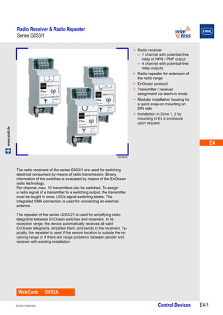
- 1. E4 E4 E4 E4 E4 E4 E4 E4 E4 E4 E4 E4 E4 E4 Radio Receiver & Radio Repeater Series G053/1 www.stahl.de Control Devices E4/1 2012-05-21·EK00·III·en Series G053/1 E4 14578E00 WebCode G053A > Radio receiver – 1 channel with potential-free relay or NPN / PNP output – 4 channel with potential-free relay outputs > Radio repeater for extension of the radio range > EnOcean protocol > Transmitter / receiver assignment via teach-in mode > Modular installation housing for a quick snap-on mounting on DIN rails > Installation in Zone 1, 2 by mounting in Ex d enclosure upon request The radio receivers of the series G053/1 are used for switching electrical consumers by means of radio transmission. Binary information of the switches is evaluated by means of the EnOcean radio technology. Per channel, max. 10 transmitters can be switched. To assign a radio signal of a transmitter to a switching output, the transmitter must be taught in once. LEDs signal switching states. The integrated SMA connection is used for connecting an external antenna. The repeater of the series G053/21 is used for amplifying radio telegrams between EnOcean switches and receivers. In its reception range, the device automatically receives all valid EnOcean telegrams, amplifies them, and sends to the receivers. Ty-pically, the repeater is used if the sensor location is outside the re-ceiving range or if there are range problems between sender and receiver with existing installation.
- 2. Radio Receiver & Radio Repeater Series G053/1 Selection Table Version Number of channels Rated operational voltage Order number Art. no. Weight kg 14725E00 Radio receiver, change-over contact 1 24 V AC / DC (-15 ... +10 %) G053/1-11-1 209453 0.068 14726E00 Radio receiver, NPN 24 V DC (-15 ... +10 %) G053/1-11-2 209454 0.056 14746E00 Radio receiver, PNP G053/1-11-3 209455 0.075 14723E00 Radio receiver, change-over contact 4 24 V AC / DC (-15 ... +10 %) G053/1-14-4 209456 0.150 14579E00 Radio repeater 1 24 V DC (-15 ... +20 %) G053/1-21 209457 0.056 E4/2 Control Devices 2012-05-21·EK00·III·en
- 3. E4 E4 E4 E4 E4 E4 E4 E4 E4 E4 E4 E4 E4 E4 Radio Receiver & Radio Repeater Series G053/1 Technical Data Electrical data Version G053/1-11-1: 1 change-over contact (relay) G053/1-11-2: NPN transistor G053/1-11-3: PNP transistor G053/1-14-4: 4 change-over contact (relays) Switching frequency approx. 9000 telegrams at repetitions / h approx. 9000 telegrams at repetitions / h Number of channels 1 (relay version potential-free) 4 (potential-free) Inputs 1 radio channel, max. 10 transmitters per channel 4 radio channels, max. 10 transmitters per channel Outputs 1 change-over contact (relay), NPN or PNP transistor 4 change-over contact (relays) Rated operational current 24 V AC: max. 0.18 A 24 V DC: max 0.22 A 24 V AC: max 0.25 A 24 V DC: max 0.1 A Rated operational voltage G053/1-11-1 (1 change-over contact): 24 V AC / DC (-15 ... +10 %) G053/1-11-2 (NPN transistor): 24 V DC (-15 ... +10 %) G053/1-11-3 (PNP transistor): 24 V DC (-15 ... +10 %) 24 V AC / DC (-15 ... +10 %) Switching capacity 250 V AC / 6 A 24 V DC / 2 A G053/1-11-1 (1 change-over contact): 250 V AC / 6 A 24 V DC / 2 A G053/1-11-2 (NPN transistor): 24 V DC / 0.2 A G053/1-11-3 (PNP transistor): 24 V DC / 0.2 A Voltage drop G053/1-11-2 (NPN transistor): 2.5 V G053/1-11-3 (PNP transistor): 2.5 V – – Utilization category G053/1-11-1 (1 change-over contact): AC-15 G053/1-11-2 (NPN transistor): DC-13 G053/1-11-3 (PNP transistor): DC-13 AC-15 DC-13 Rated insulation voltage 250 V AC 250 V AC Rated impulse withstand 2.5 kV 2.5 kV voltage Indications green LED: Rated operational voltage orange LED: Switching state signalling green LED: Rated operational voltage orange LED: Switching state signalling Interference immunity acc. to EMC Directive acc. to EMC Directive Note inductive loads (contactors, relays, etc.) are to be suppressed by suitable circuitry Wireless Antenna external antenna always required for optimum transmission range Protocol EnOcean EnOcean Frequency 868.3 MHz 868.3 MHz Ambient conditions Ambient conditions Ambient temperature 0 ... +55 °C 0 ... +55 °C Storage/transport temperature -25 ... +85 °C -25 ... +85 °C Mechanical data Connection Terminals WAGO CAGE CLAMP, Series 236 WAGO CAGE CLAMP, Series 236 Connection cross-section 0.08 ... 2.5 mm (AWG 28 ... 14) 0.08 ... 2.5 mm (AWG 28 ... 14) Vibration resistance acc. to IEC/EN 60068-2-6 acc. to IEC/EN 60068-2-6 Schock resistance acc. to IEC/EN 60068-2-27 acc. to IEC/EN 60068-2-27 Degree of pollution 2 acc. to IEC/EN 60664-1 2 acc. to IEC/EN 60664-1 Degree of protection IP20 acc. to IEC/EN 60529 IP20 acc. to IEC/EN 60529 Mounting Mounting snap mounting on DIN rail snap mounting on DIN rail 2012-05-21·EK00·III·en Control Devices E4/3
- 4. Radio Receiver & Radio Repeater Series G053/1 Technical Data Electrical data Version G053/1-21 Switching frequency approx. 9000 telegrams at repetitions / h Number of channels 1 Rated operational current max. 0.08 A Rated operational voltage 24 V DC (-15 ... +20 %) Indications green LED: Rated operational voltage orange LED: Telegram reception confirmation Interference immunity acc. to EMC Directive Wireless Antenna external antenna always required for optimum transmission range Protocol EnOcean Frequency 868.3 MHz Ambient conditions Ambient temperature 0 ... +55 °C Storage/transport temperature -25 ... +85 °C Mechanical data Connection Terminals WAGO CAGE CLAMP, Series 236 Connection cross-section 0.08 ... 2.5 mm (AWG 28 ... 14) Vibration resistance acc. to IEC/EN 60068-2-6 Schock resistance acc. to IEC/EN 60068-2-27 Degree of pollution 2 acc. to IEC/EN 60664-1 Degree of protection IP20 acc. to IEC/EN 60529 Mounting Mounting snap mounting on DIN rail Accessories and Spare Parts Designation Illustration Description Art. no. Weight kg Field intensity meter EMP 300 14589E00 mobile device for radio range testing 209483 0.085 RF magnet foot antenna 14581E00 with connecting cable 2.5 m 209484 0.060 E4/4 Control Devices 2012-05-21·EK00·III·en
- 5. E4 E4 E4 E4 E4 E4 E4 E4 E4 E4 E4 E4 E4 E4 Radio Receiver & Radio Repeater Series G053/1 Dimensional Drawings (All Dimensions in mm) - Subject to Alterations 70 60 90 45 57,5 14554E00 14577E00 35 60 90 G053/1-11-1, G053/1-11-2, G053/1-11-3 Radio Receiver, 1-Channel G053/1-14-4 Radio Receiver, 4-Channel 03243E00 35 60 90 G053/1-21 Radio Repeater 45 57,5 45 57,5 We reserve the right to make alterations to the technical data, dimensions, weights, designs and products available without notice. The illustrations cannot be considered binding. 2012-05-21·EK00·III·en Control Devices E4/5