Stahl Junction Boxes 8118 Series – ATEX Zone 1 Zone 2 Hazardous Area Junction Boxes
•
0 recomendaciones•2,600 vistas

Stahl Junction Boxes 8118 Series – ATEX Zone 1 Zone 2 Hazardous Area Junction Boxes

Recomendados
Recomendados
Más contenido relacionado
La actualidad más candente
La actualidad más candente (18)
Similar a Stahl Junction Boxes 8118 Series – ATEX Zone 1 Zone 2 Hazardous Area Junction Boxes
Similar a Stahl Junction Boxes 8118 Series – ATEX Zone 1 Zone 2 Hazardous Area Junction Boxes (20)
Más de Thorne & Derrick International
Más de Thorne & Derrick International (20)
Último
Último (20)
Stahl Junction Boxes 8118 Series – ATEX Zone 1 Zone 2 Hazardous Area Junction Boxes
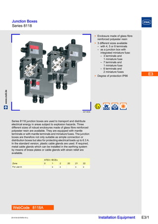
- 1. Junction Boxes Series 8118 E3 E3 E3 E3 E3 www.stahl.de Installation Equipment E3/1 2014-04-03·EKRU·III·ru E3 E3 E3 E3 E3 E3 E3 E3 E3 Series 8118 E3 02714E00 WebCode 8118A > Enclosure made of glass fibre reinforced polyester resin > 3 different sizes available – with 4, 5 or 8 terminals – as a junction box with integrated miniature fuse: – 3 terminals and 1 miniature fuse – 7 terminals and 1 miniature fuse – 6 terminals and 2 miniature fuses > Degree of protection IP66 Series 8118 junction boxes are used to transport and distribute electrical energy in areas subject to explosion hazards. Three different sizes of robust enclosures made of glass fibre reinforced polyester resin are available. They are equipped with mantle terminals or with mantle terminals and miniature fuses. The junction boxes are therefore not only suitable as simple connection or distribution boxes but also for protecting electrical loads up to 6.3 A. In the standard version, plastic cable glands are used. If required, metal cable glands which can be installed in the earthing system by means of brass plates or cable glands with strain relief are available. ATEX / IECEx Zone 0 1 2 20 21 22 For use in x x x x
- 2. Junction Boxes Series 8118 Selection Table Version Cable glands Order number Weight Position Holes Cable glands Stopping plug kg Ex e version size 1 01656E00 05349E00 4 terminals 09147E00 3 x M20 x 1.5 2 x M20 x 1.5 1 x M20 x 1.5 8118/111-401 0.280 05576E00 5 terminals 09148E00 4 x M20 x 1.5 3 x M20 x 1.5 1 x M20 x 1.5 8118/111-503 0.300 number of terminals according to the order number of holes acc. to order – – – – 8118/111-.99 Ex i version size 1 01548E00 05349E00 4 terminals 09147E00 3 x M20 x 1.5 2 x M20 x 1.5 1 x M20 x 1.5 8118/211-401 0.280 09148E00 4 x M20 x 1.5 3 x M20 x 1.5 1 x M20 x 1.5 8118/211-403 0.330 number of terminals according to the order number of holes acc. to order acc. to order acc. to order 8118/211-.99 0.336 Ex e version size 2 01655E00 05348E00 8 terminals 09149E00 4 x M25 x 1.5 3 x M25 x 1.5 1 x M25 x 1.5 8118/121-805 0.570 09151E00 6 x M20 x 1.5 4 x M20 x 1.5 2 x M20 x 1.5 8118/121-806 0.560 09151E00 6 x M25 x 1.5 4 x M25 x 1.5 2 x M25 x 1.5 8118/121-807 0.600 05576E00 5 terminals 09153E00 4 x M25 x 1.5 4 x M25 x 1.5 - - 8118/121-538 0.625 09150E00 2 x M25 x 1.5 2 x M25 x 1.5 - - 8118/121-539 0.600 number of terminals according to the order number of holes acc. to order – – – – 8118/121-.99 05348E00 8 terminals 09149E00 3 x M25 x 1.5 -* 3 x M25 x 1.5 8118/121- 804-2 0.750 Ex i version size 2 10549E00 05348E00 8 terminals number of holes acc. to order acc. to order acc. to order 8118/221-899 0.500 E3/2 Installation Equipment 2014-04-03·EKRU·III·ru
- 3. Junction Boxes Series 8118 E3 E3 E3 E3 E3 E3 E3 E3 E3 E3 E3 E3 E3 E3 Selection Table Version Cable glands Order number Weight Ex e version size 3 01654E00 05348E00 8 terminals Position Holes Cable glands Stopping 09155E00 plug kg 6 x M32 x 1.5 4 x M32 x 1.5 2 x M32 x 1.5 8118/131-811 0.850 09154E00 8 x M25 x 1.5 6 x M25 x 1.5 4 x M25 x 1.5 8118/131-814 0.850 Number of terminals and fuses acc. to order number of holes acc. to order – – – – 8118/131-.99 05348E00 8 terminals 09156E00 4 x M25 x 1.5 -* 4 x M25 x 1.5 8118/131- 842-2 0.980 Ex i version size 3 10550E00 05348E00 8 terminals number of holes acc. to order acc. to order acc. to order 8118/231-899 0.612 Ex e version size 1 01652E00 05384E00 3 terminals + 1 fuse 09148E00 4 x M20 x 1.5 2 x M20 x 1.5 2 x M20 x 1.5 8118/113-303 0.330 Ex e version size 2 01650E00 Number of terminals and fuses acc. to order number of holes acc. to order – – – – 8118/123-.99 Note Standard: cable glands, Series 8161 Option: metal cable glands with brass plate A non-standard arrangement is possible when using cable glands of the Series 8161 as well as when using cable glands with strain relief. Cable glands and stopping plugs are enclosed separately. The fuse must be ordered separately. 2014-04-03·EKRU·III·ru Installation Equipment E3/3
- 4. Junction Boxes Series 8118 Explosion Protection Global (IECEx) Versions junction box without miniature fuse junction box with miniature fuse Type 8118/.11 8118/.21 8118/.31 8118/113 8118/123 Gas and dust IECEx PTB 06.0026 IECEx PTB 06.0026 Ex e Ex e IIC T6 ... T4 Gb Ex i Ex ia [ia Ga] ib IIA, IIB, IIC T6 ... T5 Gb Ex em II T * * depending on miniature fuse used Ex tb IIIC T80°C ... T130°C Db Ex tD A21 IP66 T80°C, T95°C, T130°C Europe (ATEX) Versions junction box without miniature fuse junction box with miniature fuse Type 8118/.11 8118/.21 8118/.31 8118/113 8118/123 Gas and dust PTB 99 ATEX 3103 PTB 99 ATEX 3103 Ex e E II 2 G Ex e II T6, T5, T4 Ex i E II 2 G Ex ia/ib IIA, IIB, IIC T6, T5 E II 2 D Ex tD A21 IP66 T80°C, T95°C, T130°C E II 2 G Ex em II T * * depending on miniature fuse used E II 2 D Ex tD A21 IP66 T80°C, T95°C, T130°C Certifications and certificates Certificates IECEx, ATEX, Brazil (INMETRO), China (China-Ex), India (PESO), Kazakhstan (GOST K), Korea (KCs), Russia (GOST R), Ukraine (TR) Technical Data Electrical data Versions junction box without miniature fuse junction box with miniature fuse Type 8118/.11 8118/.21 8118/.31 8118/113 8118/123 Rated operational voltage 550 V 750 V 750 V 250 or 500 V , depending on miniature fuse used Connection Terminals Current carrying capacity at conductor cross-section of max. 24 A 4 mm2 max. 32 A 6 mm2 max. 44 A 10 mm2 max. 24 A 4 mm2 max. 32 A 6 mm2 Max. number of miniature fuses – – – – – – 1 x 8560 2 x 8560 Ambient conditions Ambient temperature Mechanical data Ex e: - 20 ... + 55 °C Ex i: - 20 ... + 75 °C Degree of protection IP66 Material - 50 ... + 55 °C with special cable glands - 50 ... + 75 °C with special cable glands Enclosure glass fibre reinforced polyester resin, dark grey similar to RAL 7012, impact resistance > 7 J, flame retardant acc. to IEC/EN 60695, UL 94, ASTM D635 Seal Polyurethane, foamed Cover lock with captive M4 stainless steel combo head screws or E3/4 Installation Equipment 2014-04-03·EKRU·III·ru
- 5. Junction Boxes Series 8118 E3 E3 E3 E3 E3 E3 E3 E3 E3 E3 E3 E3 E3 E3 Technical Data Mounting / Installation Versions junction box without miniature fuse junction box with miniature fuse Type 8118/.11 8118/.21 8118/.31 8118/113 8118/123 Cable gland Standard Cable glands, series 8161 and stopping plugs, series 8290 are enclosed separately. Cable glands, series 8161 and stopping plugs, series 8290 are enclosed separately. 3 x M20 4 x M20 6 x M20 4 x M25 6 x M25 8 x M25 6 x M32 – – – – Special version Holes according to order. Metal cable glands with brass plates or cable entry glands are possible. Holes according to order. Metal cable glands with brass plates or cable entry glands are possible. Connection Terminals Type of terminals mantle terminals mantle terminals mantle terminals mantle terminals mantle terminals Max. number 4 or 5 5 or 8 8 3 when using 1 miniature fuse 7 when using 1 miniature fuse, 6 when using 2 miniature fuses Max. conductor cross-section 4 mm2 solid 6 mm2 solid 10 mm2 solid 4 mm2 solid 6 mm2 solid Accessories and Spare Parts Designation Figure Description Art. no. Weight kg Brass plate with thread 05735E00 for earth continuity when using metal glands; threads are cut acc. to order 133208 0.030 133182 0.060 133198 0.080 133202 0.140 Cross connector 05353E00 133348 0.002 133366 0.003 133385 0.005 for cable glands can be installed into enclosure Size 1 Size 2 Size 3 1 x M20 x 1.5 Side C / D Side C / D Side C / D 1 x M25 x 1.5 1 x M32 x 1.5 2 x M20 x 1.5 Side C / D Side C / D 2 x M25 x 1.5 Side C / D Side C / D 2 x M32 x 1.5 Side C / D 8118/.1. 8118/.2. 8118/.3. for bridging 2 side by side mantle terminals 2014-04-03·EKRU·III·ru Installation Equipment E3/5
- 6. Junction Boxes Series 8118 Accessories and Spare Parts Designation Figure Description Order number Weight kg Fuse 8560/51, 250 V UC Packaging units IN [A] [pieces] 0.032 5 0.05 5 0.063 5 0.08 5 0.1 5 0.125 5 0.16 5 0.2 5 0.25 5 0.315 5 0.4 5 0.5 5 0.63 5 0.8 5 1.0 5 1.25 5 2.0 5 4.0 5 8560/61, 500 V UC Packaging units IN [A] [pieces] 0.08 5 0.1 5 0.125 5 0.2 5 0.25 5 0.315 5 0.4 5 0.5 5 05736E00 8560/51-4021 0.210 8560/51-4031 0.210 8560/51-4041 0.210 8560/51-4051 0.210 8560/51-4061 0.210 8560/51-4071 0.210 8560/51-4081 0.210 8560/51-4091 0.210 8560/51-4101 0.210 8560/51-4111 0.210 8560/51-4131 0.210 8560/51-4141 0.210 8560/51-4151 0.210 8560/51-4171 0.210 8560/51-4181 0.210 8560/51-4191 0.210 8560/51-4222 0.210 8560/51-4252 0.210 8560/61-4051 0.210 8560/61-4061 0.210 8560/61-4071 0.210 8560/61-4091 0.210 8560/61-4101 0.210 8560/61-4111 0.210 8560/61-4131 0.210 8560/61-4141 0.210 E3/6 Installation Equipment 2014-04-03·EKRU·III·ru
- 7. Junction Boxes Series 8118 E3 E3 E3 E3 E3 E3 E3 E3 E3 E3 E3 E3 E3 E3 Dimensional Drawings (All Dimensions in mm) - Subject to Alterations 04466E00 04467E00 04468E00 04469E00 8118/.1. size 1 8118/.2. size 2 8118/.3. size 3 Size Length [mm] min. max. M20 25 31 M25 27 33 M32 32 39 Additional dimension for cable glands, Series 8161 We reserve the right to make alterations to the technical data, dimensions, weights, designs and products available without notice. The illustrations cannot be considered binding. 2014-04-03·EKRU·III·ru Installation Equipment E3/7