New Technology: 核磁共振相容節律器-"MRI Standard of Care for Pacemaker"_20131019南區
•Descargar como PPT, PDF•
5 recomendaciones•2,489 vistas


Recomendados
Recomendados
Más contenido relacionado
Más de Taiwan Heart Rhythm Society
Más de Taiwan Heart Rhythm Society (20)
Último
Último (20)
New Technology: 核磁共振相容節律器-"MRI Standard of Care for Pacemaker"_20131019南區
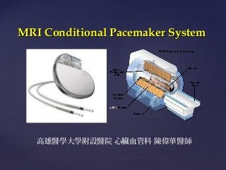
- 1. MRI Conditional Pacemaker System { 高雄醫學大學附設醫院 心臟血管科 陳偉華醫師
- 2. Contents What kind of activity that pacemaker patient could not do ? What is MRI and why we need this kind of examination ? What is the possible complication of MRI examination in pacemaker patient ? How the CIED company solve this problems? Recent available MRI conditional pacemaker in Taiwan
- 3. What does the pacemaker afraid of ?
- 6. Why we need MRI examination ?
- 7. Why MRI Scans are Important to Clinical Medicine Fastest Growing Standard of Care in Diagnostic Imaging 1 Superior Soft Tissue Imaging2 Primary method to evaluate: Central Nervous System Musculoskeletal System Oncological Conditions Some Cardiovascular Disorders MRI complements CT (which excels when imaging bony structures) No radiation risk to patient or healthcare provider Since the absence of x-ray radiation, MRI is optimal for follow-up of chronic diseases that require repeat imaging and for diagnostic imaging in young patients and women of childbearing age. 1. Kaiser CP. Soaring MRI use draws scrutiny. Diagnostic Imaging Online January 4, 2002. CMP United Business Media: A CMP Healthcare Media Web Site. Available at: http://www.diagnosticimaging.com/dinews/2002010401.shtml. Accessed October 19, 2004. 2. Duru F, Luechinger R, Scheidegger MB, et al. Pacing in magnetic resonance imaging environment: Clinical and technical considerations on compatibility. Eur Heart J. January 2001;22(2):113-124.
- 8. Cervical spine computed tomography (CT) vs MRI in a patient with neck pain and fever. Nazarian S et al. Circ Arrhythm Electrophysiol 2013;6:419-428 Copyright © American Heart Association
- 9. Brain computed tomography (CT) vs MRI in a patient with weakness. Nazarian S et al. Circ Arrhythm Electrophysiol 2013;6:419428 Copyright © American Heart Association
- 10. Cardiac computed tomography (CT) vs MRI in a patient with facial swelling. Nazarian S et al. Circ Arrhythm Electrophysiol 2013;6:419428 Copyright © American Heart Association
- 11. Clinical Need: MRI Scanning Capabilities of the Thoracic Region 32% thoracic • • 60 million MRI scans performed worldwide annually1, with prevalence growing for MRI as a preferred diagnostic modality Over 30% of all MRI scans are done in the thoracic region2 1. www.browsemedic.com/MRI 2. 2007 MRI Market Summary Report – Commissioned by St. Jude Medical, Inc. June 20083
- 14. What is MRI and what could it do with our device ?
- 15. Anatomy of an MRI Scanner Three basic components: 15 Static magnet Gradient magnets RF coil Determines magnetic strength of scanner: 1.5 or 3.0 tesla 1 tesla (T) = 10,000 gauss. The earth’s magnetic field = 0.5 gauss. Magnet response in SJM pacemakers occurs in response to 8-10 gauss directly over the pacemaker.
- 18. Variables Affecting Magnitude of Risks Length/position of pacing leads Patient and device position within machine Patient factors / medical history MRI scan duration Blood flow at lead/tissue interface Strength of RF field Target anatomy of scan Type of imaging MRI sequence Pacemaker and Lead Design
- 19. Force , torque and vibration The most intuitive potential interaction of implanted devices with an external magnetic field is the possibility for movement and dislocation of the device because of magnetic force. Current lead designs contain little or no ferromagnetic components and are not likely to experience force and torque. The potential for movement of a pacemaker or ICD generator in the MRI environment depends on the magnetic field strength ferromagnetic properties of the device components the implant distance from the magnet bore and the stability of the implant.
- 20. Current/ voltage induction The RF and pulsed gradient magnetic fields of the MRI scanner may induce electric currents in leads within the field, if the lead is part of a current loop that is completed through the body. The ratio of lead length versus RF wavelength and lead conformations, such as loops, are strongly associated with the extent of current induction.
- 21. Heating and Tissue Damage Metallic devices and leads can act as an antenna thus amplifying local radiofrequency energy deposition. Fractured leads or lead loop configurations may increase the potential for heating. Epicardial leads that are not cooled by blood flow and abandoned leads may also be prone to increased heating. Essentially the lead acts as an antenna and picks up RF currents that can generate heating upon reaching the tissues at the lead electrodes. Resistance of cardiac tissue to current flow generates heat near the lead tip. Heating at the lead tip can result in threshold changes.
- 22. – 22
- 23. Lead Heating Clinical Impact • PCT = Pacing Capture Threshold • PCT is lowest at implant • Healing produces scar • Increased distance increases PCT • Significant heating causes tissue damage • Increased scar volume increases PCT
- 24. Malfunction of devices CIED may provide unnecessary therapies or fail to provide necessary therapies when placed in the MRI scanner. Pacemakers and ICDs have the potential for receiving electromagnetic interference (EMI) in the MRI environment, resulting in: radiofrequency noise tracking asynchronous pacing inhibition of demand pacing delivery of ICD therapies programming changes loss of function.
- 25. Malfunction of devices The static magnetic field of the MRI scanner can also alter device function by inducing unexpected reed switch opening or closure. In addition, temporary programming changes made to avoid device interaction with the MRI scanner (such as disabling of tachycardia therapies) may lead to catastrophic results if a spontaneous arrhythmia occurs and is not recognized.
- 26. Tachycardia induction due to gradients
- 27. Gradient Mechanism Gradient Waveform Amplitude Gradient Induced Pulse ~ 0.005 ms 0.4 ms Pacing Pulse Gradient Induced Pulse Time 500 ms – 750 ms
- 28. Unintended Cardiac Stimulation (Gradient Pulses) Lead provides path for gradient magnetic fields to induce voltages and give rise to electrical currents If these currents are generated outside of refractory periods they may result in arrhythmias Induced arrhythmias 6 non-pacemaker-dependent patients died during an MRI conducted without cardiac monitoring1 3 cases showed evidence of induced ventricular fibrillation.
- 29. Unintended Stimulation Clinical Impact Stimulation hazard gradient-induced high rate pacing EKG Pulse Ox Canine Test Start of Scan !!!!!!! The MRI scanner is pacing the heart !!!!!!!!
- 30. What CIED company have to do ? MRI-conditional pacemaker
- 31. no inhibition of pacemaker output or cardiac arrest no sustained ventricular arrhythmias no unexpected changes of heart rate no electrical resets no pacemaker system disturbances and no sensation of torque or pain
- 32. MRI Safety Terminology MR Safe MR Unsafe MR Conditional An item that has been demonstrated to pose no known hazards in a specified MRI environment with specified conditions of use. *ASTM standard F2503: Standard Practice for Marking Medical Devices and Other Items for Safety in the Magnetic Resonance Environment
- 33. MRI Conditional (MR Conditional) A device or implant that may contain magnetic, electrically conductive or RF reactive components that is safe for operations to the MRI, provided the conditions for safe operation are defined and observed FDA limits 4 W/kg averaged over the whole body for a 15-minute period (reflects our labeling) 3 W/kg averaged over the head for any 10-minute period 8 W/kg in any gram of tissue in the extremities for any period of 5 minutes 33
- 34. Device Design Solutions Minimize ferromagnetic content Hybrid-case connection Hall sensor Optimize input circuitry
- 35. Lead Reliability and Filters An MRI conditional pacing lead must be able to withstand the magnetic forces, gradients, and RF energy present during scanning and the harsh environment of the human body. Filter board added to pacemaker hardware. 2 filters are incorporated into the pacing lead to reduce the risk of heating from RF signals. 35
- 36. PATIENT MANAGEMENT 1. 2. Identity card Radiopaque identification
- 39. For patients who require pacing support, program the device to an asynchronous pacing mode (DOO, AOO, VOO). For patients who do not require pacing support, program the device to the non-pacing mode (ODO).
- 41. Recent MRI Conditional Pacemaker , CRT and ICD in the Market
- 42. St Jude Medical Accent MRI RF Pacemaker
- 43. Medtronic Ensura MRI SureScan Pacing System ( DDDR) Advisa MRI SureScan Pacing System ( DDDRP)
- 44. Biotronik
- 45. Many Thanks and Good Bye……..
Notas del editor
- Cervical spine computed tomography (CT) vs MRI in a patient with neck pain and fever. The CT image in the left panel shows degenerative changes and possible C3-4 spinal stenosis, but no evidence of epidural or soft tissue abscess. The T1-weighted MRI of the same patient in the right panel shows signal hypo-intensity in the C3-4 vertebral bodies in addition to abnormal signal in the para-vertebral soft tissues consistent with osteomyelitis and epidural phlegmon with mass effect upon the cervical spinal cord. C3 indicates cervical vertebral body 3; C4, cervical vertebral body 4; and T1 hypo-intensity, hypo-intensity on T1-weighted image.
- Brain computed tomography (CT) vs MRI in a patient with weakness. The CT image in the left panel shows no evidence of acute infarction. The MRI of the same patient (obtained the same day) in the right panel shows acute left parietal infarction (arrow).
- Cardiac computed tomography (CT) vs MRI in a patient with facial swelling. The CT image in the left panel reveals a poorly defined filling defect of the right atrium. The MRI in the right panel reveals a sarcoma which extends from the anterior mediastinum to the interatrial septum, completely obliterates the right atrial cavity (note difference in signal intensity of right atrial mass vs left atrial cavity), compresses the left upper lobe pulmonary vein, and abuts the aortic root. The extent of lead “star” artifact in the CT panel is significantly larger than the lead susceptibility artifact with MRI. The bottom panel shows a right lateral 3D MRI reconstruction with minimal device or lead artifact. The sarcoma nearly completely obstructs the superior and inferior vena cava. IVC indicates inferior vena cava; LA, left atrium; and SVC, superior vena cava.
- This diagram shows the lead – after the helix has been screwed into the cardiac tissue – immediately after implant. The pacing capture threshold is the lowest because there is no scar tissue. Scar tissue forms as part the normal healing process – and the increased distance to the viable myocardium – produces an increase in pacing capture threshold. Based upon 40 years of literature – subtle changes in the viable myocardium are reflected in pacing capture threshold. Second Build – Extreme RF power levels – produced higher lead tip heating – causing damaged tissue to be replaced by scar tissue – which produces an additional increase in pacing capture threshold.
- Looking at the gradient mechanism - the blue waveform is a representative gradient signal – which repeats for the duration of the scan sequence. First build – This signal is picked up by the pacing lead – and is transformed by the pacemaker – into a very narrow pulse. Note – that the width of the pulse – is not dependent on the gradient waveform – it is dependent on the pacemaker input circuit design. Second build – The green pulses on the bottom represent normal pacing pulses and – 3rd build – the narrow red pulses were produced indirectly from the gradient field. The amplitude of these narrow pulses – must be quite high to cause stimulation – because they are 100 times narrower than a normal pacing pulse.
- This strip shows what can happen when the scanner paces the heart. On the top left we have a normal EKG – and on the bottom left normal pulse oximetry. When the imaging sequence starts – indicated by the vertical green line – the scanner begins pacing the heart at a very high rate (300 ppm)– a rate that is so high – there is a loss of hemodynamic function. When the scan is stopped – hemodynamic function returns to normal. In this particular case the hazard was created by the gradient field – but this can also occur as a result of the RF field – through a different mechanism.
- MR Safe Poses no known hazard in any MR environment MR Conditional No known hazards under specific conditions. The conditions must be specified in the labeling. MR Unsafe Poses hazards in all MR environments
- The MRI knowledge gained during the early years resulted in design changes to our pacemaker portfolio prior to the Advsia MRI product development program. Build 1 – The first of these changes was minimizing the ferromagnetic content in the device – which minimizes the force and torque hazards. Build 2 – The magnetic reed switch was replaced with a solid state hall sensor for entering magnet mode. For those not familiar with magnet mode – it puts the device in a known state in the presence of a moderate magnetic field. One use for magnet mode – is the establishment of a telemetry session to communicate with the device. The mechanical reed switches are known to be problematic in the MRI environment – and could result in numerous pacemaker malfunctions during or post MRI. All of these needed design changes were incorporated into the base device before starting the MRI SureScan development program. Build 3 – optimizing the input circuitry capacitance to reduce the risk of unintended cardiac stimulation. Build 4 – Hybrid component changes were made to enhance the immunity to the gradient field. One of these changes was made as a result of testing on our high dB/dt tester. The robustness of our test methods allowed us to identify this relevant and potentially serious problem. In conclusion – we made numerous design changes to make the device safe in the MRI environment.
- Note “May be eligible”