Más contenido relacionado
Similar a Using the guardian i-stop Test Probe (20)
Using the guardian i-stop Test Probe
- 1. Application Note
Using the Guardian I-Stop Reverse Test Probe
to Locate the Source of Ingress
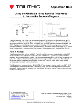
The I-Stop Reverse Test Probe is an accessory for the 860 DSPi Multifunction Cable Analyzer, which
simplifies the location of reverse ingress sources. Just screw the probe into a KS port on a distribution
tap, connect your 860 DSP to the handy -20 dB test port, and press the button on the I-Stop Probe: The
DSP’s display shows you the ingress sources down to the tap without removing reverse modules or
diplexers and without disrupting forward or reverse service. To prevent overloading caused by the forward
signal levels present, it is recommended that you use a Return Measurement Lowpass Filter (TLB-6).
How it works:
The I-Stop probe is used with the 860 DSP. The DSP is a field instrument that works with a 9581 SST
Headend Unit mounted in the Hub; together, the SST and DSP are a system used to balance return
amplifiers and hunt for sources of ingress. The ingress spectra displayed by the DSP are transmitted to it
by the SST and show the amount of ingress arriving from a given node’s service area. If an outbreak
occurs, the operator uses the I-Stop probe and the 860 DSP Field Unit to find where in that node’s
service area the ingress is entering the system.
The I-Stop contains two assemblies, a -20 dB “SPD-20” type test point adapter usable from 5-870 MHZ:
and a frequency-limited termination that is impressed across the CATV line when the I-Stop’s button is
depressed. The termination is preceded by a “half-diplexer” so that the effect of the termination is limited
to return band frequencies.
For Additional Help Contact
Trilithic Applications Engineering Using the Guardian I-Stop Reverse Test Probe to Locate
1-800-344-2412 or 317-895-3600 the Source of Ingress
support@trilithic.com or P/N 0010275022 – Rev 8/09
www.trilithic.com 1 of 2
Copyright © 2009 Trilithic, Inc. All Rights Reserved.
- 2. Application Note
When the I-Stop probe and 860 DSP are connected to the tap as shown in Fig 1, the display of the DSP
might look like the example in Fig 2. When the button on the I-Stop probe is then pressed, the terminator
loads down the return path and decreases the gain in that path by 4-6 dB. (This range of values was
chosen to allow a clearly visible response on the DSP’s display while not attenuating the return path
enough to interrupt service.) Whether a change occurs in the DSP’s ingress display when the button is
depressed depends on whether the ingress source is closer to, or farther from the node, than the tap that
it is connected to:
• If the source is farther from the node, and on this distribution line, the ingress signal will be
flowing through the tap to which the probe is connected. When the button is pressed, the ingress
will decrease by 4-6 dB, as measured by the 9581 SST connected in the Hub, which transmits
the ingress display to the DSP. The operator would observe that the ingress decreases when the
I-Stop’s button is pushed and knows that its source is farther out on this distribution line.
• If the ingress is entering the distribution system through another line, or is closer to the node on
this line, the ingress will not be flowing through the tap, so pressing the button will have no effect
on the ingress spectra measured by the 9581 SST in the Hub and transmitted to the Operator’s
860 DSP. Because the DSP’s display does not change when the probe’s button is pressed, the
operator knows the ingress source is either closer to the node or on another line.
For Additional Help Contact
Trilithic Applications Engineering Using the Guardian I-Stop Reverse Test Probe to Locate
1-800-344-2412 or 317-895-3600 the Source of Ingress
support@trilithic.com or P/N 0010275022 – Rev 8/09
www.trilithic.com 2 of 2
Copyright © 2009 Trilithic, Inc. All Rights Reserved.