SlideShare una empresa de Scribd logo
1 de 20
Descargar para leer sin conexión
Chapter 3: Planning

                                             Chapter 3: Project Planning


3.1 Introduction

Planning is a general term that sets a clear road map that should be followed to reach a
destination. The term, therefore, has been used at different levels to mean different things.
Planning involves the breakdown of the project into definable, measurable, and identifiable
tasks/activities, and then establishes the logical interdependences among them. Generally,
planning answers three main questions:

   -     What is to be done?
   -     How to do it?
   -     Who does it?

In construction, for example, plans may exist at several levels: corporate strategic plans, pre-
tender plans, pre-contract plans, short-term construction plans, and long-term construction plans.
These plans are different from each other; however, all these plans involve four main steps:

   -     Performing breakdown of work items involved in the project into activities.
   -     Identifying the proper sequence by which the activities should be executed.
   -     Activities representation.
   -     Estimating the resources, time, and cost of individual activities.

Detailed planning for tendering purposes and the preparation of construction needs to be
conducted through brainstorming sessions among the planning team. The inputs and outputs of
the planning process are shown in Figure 3.1.

                Contract information                                      Activities
                           Drawings                                       Relationships among activities
                       Specifications                                     Method statement                 OUTPUTS
       INPUTS


                  Available resources                                     Responsibility
                                                  PLANNING
                   Bills of quantities                                    Reporting levels
                         Site reports                                     Project network diagram
                  Organizational data                                     Activities duration
                Construction methods                                      Activities cost

                                         Figure 3.1: Planning inputs and outputs

Planning requires a rigorous effort by the planning team. A planner should know the different
categories of work and be familiar with the terminology and knowledge used in general practice.
Also, the planning tem should seek the opinion of experts including actual construction
experience. This helps produce a realistic plan and avoids problems later on site.


Construction Management                                    29                                   Dr. Emad Elbeltagi
Chapter 3: Planning

3.2 Project Planning Steps

The following steps may be used as a guideline, or checklist to develop a project plan:
   1. Define the scope of work, method statement, and sequence of work.
   2. Generate the work breakdown structure (WBS) to produce a complete list of activities.
   3. Develop the organization breakdown structure (OBS) and link it with work breakdown
       structure o identify responsibilities.
   4. Determine the relationship between activities.
   5. Estimate activities time duration, cost expenditure, and resource requirement.
   6. Develop the project network.

3.2.1   Work breakdown structure (WBS)

The WBS is described as a hierarchical structure which is designed to logically sub-divide all the
work-elements of the project into a graphical presentation. The full scope of work for the project
is placed at the top of the diagram, and then sub-divided smaller elements of work at each lower
level of the breakdown. At the lowest level of the WBS the elements of work is called a work
package. A list of project’s activities is developed from the work packages.

Effective use of the WBS will outline the scope of the project and the responsibility for each
work package. There is not necessarily a right or wrong structure because what may be an
excellent fit for one discipline may be an awkward burden for another.

To visualize the WBS, consider Figure 3.2 which shows a house construction project.


                                              House


                   Civil                    Plumping                    Electrical


        Foundations       Walls/Roof   Piping        H/C Water     Wiring        Fittings


                                Figure 3.2: WBS and their description

As shown in Figure 3.2, level 1 represents the full scope of work for the house. In level 2, the
project is sub-divided into its three main trades, and in level 3 each trade is sub-divided to
specific work packages.

Figure 3.3 shows another example for more detailed WBS, in which the project WBS is divided
into five levels:


Construction Management                         30                               Dr. Emad Elbeltagi
Chapter 3: Planning

Level 1                              Gas development project


Level 2                   Recovery unit 300                     Process unit 400


Level 3               Train 2        Train 1            Gas treating    Separation and stabilization


Level 4         Instrumentation      Structural steel           Civil          Piping


                                                                               Piping
Level 5                                                                      fabrication

                                   Figure 3.3: Five levels WBS

    Level 1: The entire project.
    Level 2: Independent areas.
    Level 3: Physically identifiable sections fully contained in a level 2 area, reflect construction
              strategy.
    Level 4: Disciplines set up schedule.
    Level 5: Master schedule activities, quantity, duration.

Example 3.1:

The WBS for a warehouse is as follow:


Foe more details, another two levels (third and fourth levels) can be added as shown below:


Construction Management                            31                                      Dr. Emad Elbeltagi
Chapter 3: Planning


Accordingly, a complete WBS for the warehouse project can be shown as follow (Figure 3.4):


                              Figure 3.4: Warehouse project WBS

WBS and organizational breakdown structure (OBS)

The WBS elements at various levels can be related to the contractor’s organizational breakdown
structure (OBS), which defines the different responsibility levels and their appropriate reporting
needs as shown in Figure 3.5. The figure, also, shows that work packages are tied to the
company unified code of accounts. The unified code of accounts allows cataloging, sorting, and
summarizing of all information. As such, the activity of installing columns formwork of area 2,
for example, which is the responsibility of the general contractor’s formwork foreman, has a
unique code that represents all its data.

WBS coding

A project code system provides the framework for project planning and control in which each
work package in a WBS is given a unique code that is used in project planning and control. The
coding system provides a comprehensive checklist of all items of work that can be found in a
specific type of construction. Also, it provides uniformity, transfer & comparison of information
among projects. An example of this coding system is the MasterFormat (Figure 3.6) which was
developed through a joint effort of 8 industry & professional associations including:
Construction Specifications Institute (CSI); and Construction Specifications Canada (CSC).

Construction Management                        32                               Dr. Emad Elbeltagi
Chapter 3: Planning

Figure 3.7 shows an example of the coding system using a standardize system as the
MasterFormat. The Master format is divided into 16 divisions as follows:
    1)              General Requirements.
    2)              Site work.
    3)              Concrete.
    4)              Masonry.
    5)              Metals.
    6)              Woods & Plastics.
    7)              Thermal & Moisture Protection.
    8)              Doors & Windows.
    9)              Finishes.
    10)             Specialties.
    11)             Equipment
    12)             Furnishings.
    13)             Special Construction.
    14)             Conveying Systems.
    15)             Mechanical.
    16)             Electrical.

                                                                                                                                WBS (Work elements)

                                                                                                                                         Project


                                                                                                                               Area 1    Area 2    Area 3 ……

                                                                                                                                Beams    Columns   Slabs    ……
                                                                            superintendent


                                                                                                                            Formwork Reinforcement Concreting ……
                                                                              Electrical
                                                            Subcontractor
       OBS (Responsibility & reporting)


                                                                                                            Concrete
                                                                                                            foreman
                                                                 B
                                          Project manager


                                                                                           superintendent


                                                                                                            Formwork
                                                            contractor


                                                                                                             foreman


                                                                                                                       Control account
                                                             General


                                                                                               Civil
                                                            Subcontractor


                                                                                                            foreman
                                                                                                             Rebar
                                                                            superintendent
                                                                             Mechanical
                                                                 A


                                                                               Figure 3.5: WBS linked to the OBS


Construction Management                                                                                                33                                  Dr. Emad Elbeltagi
Chapter 3: Planning

CSI – Masterformat (Building Construction)


                                         Figure 3.6: MasterFormat coding ssytem
Construction Management
Construction Management                                    34
                                                           34           Dr. Emad Elbeltagi   Dr. Eamd Elbeltagi
Chapter 3: Planning


                       Figure 3.7: An example of an activity coding system

Project activities

The building block (the smallest unit) of a WBS is the activity, which is a unique unit of the
project that has a specified duration. An activity is defined as any function or decision in the
project that: consumes time, resources, and cost. Activities are classified to three typs:

        Production activities: activities that involve the use of resources such as labor,
        equipment, material, or subcontractor. This type of activities can be easily identified by
        reading the project’s drawings and specifications. Examples are: excavation, formwork,
        reinforcement, concreting, etc. each production activity can have a certain quantity of
        work, resource needs, costs, and duration.

        Procurement activities: activities that specify the time for procuring materials or
        equipment that are needed for a production activity. Examples are: brick procurement,
        boiler manufacturing and delivery, etc.

        Management activities: activities that are related to management decisions such as
        approvals, vacations, etc.

An activity can be as small as “steel fixing of first floor columns” or as large as “construct first
floor columns”. This level of details depends on the purpose of preparing the project plan. In the
pre construction stages, less detailed activities can be utilized, however, in the construction
stages, detailed activities are required. Accordingly, level of details depends on: planning stage,
size of the project, complexity of the work, management expertise.


Construction Management                         35                                Dr. Emad Elbeltagi
Chapter 3: Planning

Example 3.2:

Figure 3.8 shows a double-span bridge. Break the construction works of the bridge into
activities. The plan will be used for bidding purposes.
                                                     Hand rail

                                                                             Road base right
          Road base left
                                         Deck slab
                                                             Precast beams


                                   Figure 3.8: Double span bridge

A list of the double-span bridge activities is shown in Table 3.1

                             Table 3.1: Activities of the double-span bridge
                              Activity Description
                                   10      Set-up site
                                   14      Procure reinforcement
                                   16      Procure precast beams
                                   20      Excavate left abutment
                                   30      Excavate right abutment
                                   40      Excavate central pier
                                   50      Foundation left abutment
                                   60      Foundation right abutment
                                   70      Foundation central pier
                                   80      Construct left abutment
                                   90      Construct right abutment
                                   100     Construct central pier
                                   110     Erect left precast beams
                                   120     Erect right precast beams
                                   140     Fill left embankment
                                   150     Fill right embankment
                                   155     Construct deck slab
                                   160     Left road base
                                   170     Right road base
                                   180     Road surface
                                   190     Bridge railing
                                   200     Clear site


3.2.2   Activities relationships

In order to identify the relationships among activities, the planning team needs to answer the
following questions for each activity in the project:

   -    Which activities must be finished before the current one can start?
   -    What activity(ies) may be constructed concurrently with the current one?

Construction Management                              36                            Dr. Emad Elbeltagi
Chapter 3: Planning

   -   What activity(ies) must follow the current one?

A circle of activity precedences will result in an impossible plan. For example, if activity A
precedes activity B, activity B precedes activity C, and activity C precedes activity A, then the
project can never be started or completed. Figure 3.9 illustrates the resulting activity network.


                      Figure 3.9: Example of a circle of activity precedence

Example 3.3:

Suppose that a site preparation and concrete slab foundation construction project consists of nine
different activities:
             A. Site clearing (of brush and minor debris),
             B. Removal of trees,
             C. General excavation,
             D. Grading general area,
             E. Excavation for utility trenches,
             F. Placing formwork and reinforcement for concrete,
             G. Installing sewer lines,
             H. Installing other utilities,
             I. Pouring concrete.

Activities A (site clearing) and B (tree removal) do not have preceding activities since they
depend on none of the other activities. We assume that activities C (general excavation) and D
(general grading) are preceded by activity A (site clearing). It might also be the case that the
planner wished to delay any excavation until trees were removed, so that B (tree removal) would
be a precedent activity to C (general excavation) and D (general grading). Activities E (trench
excavation) and F (concrete preparation) cannot begin until the completion of general excavation
and grading, since they involve subsequent excavation and trench preparation. Activities G
(install lines) and H (install utilities) represent installation in the utility trenches and cannot be
attempted until the trenches are prepared, so that activity E (trench excavation) is a preceding
activity. We also assume that the utilities should not be installed until grading is completed to
avoid equipment conflicts, so activity D (general grading) is also preceding activities G (install
sewers) and H (install utilities). Finally, activity I (pour concrete) cannot begin until the sewer
line is installed and formwork and reinforcement are ready, so activities F and G are preceding.
Other utilities may be routed over the slab foundation, so activity H (install utilities) is not
necessarily a preceding activity for activity I (pour concrete). The result of our planning is the
immediate precedence shown in Table 3.2.
Construction Management                          37                                 Dr. Emad Elbeltagi
Chapter 3: Planning

          Table 3.2: Precedence relations for Example 3.3
           Activity Description                                                        Predecessors
               A     Site clearing                                                         ---
               B     Removal of trees                                                      ---
               C     General excavation                                                     A
               D     Grading general area                                                   A
               E     Excavation for utility trenches                                       B,C
               F     Placing formwork and reinforcement for concrete                       B,C
               G     Installing sewer lines                                                D,E
               H     Installing other utilities                                            D,E
               I     Pouring concrete                                                      F,G


Example 3.4:

Determine the relationships between activities of the project studied in Example 3.2.

                   Table 3.3: Solution of Example 3.4
                    Activity             Description               Predecessors
                          10    Set-up site                                  ---
                          14    Procure RFT                                  ---
                          16    Procure P.C. Beams                           ---
                          20    Excavate left abutment                      10
                          30    Excavate right abutment                     10
                          40    Excavate central pier                       10
                          50    Foundation left abutment                  14, 20
                          60    Foundation right abutment                 14, 30
                          70    Foundation central pier                   14, 40
                          80    Construct left abutment                     50
                          90    Construct right abutment                    60
                          100   Construct central pier                      70
                          110   Erect left P.C. Beams                   16, 80, 100
                          120   Erect right P.C. Beams                  16, 90, 100
                          140   Fill left embankment                        80
                          150   Fill right embankment                       90
                          155   Construct deck slab                      110, 120
                          160   Left road base                              140
                          170   Right road base                             150
                          180   Road surface                           155, 160, 170
                          190   Bridge railing                              155
                          200   Clear site                               180, 190


Logical relationship considering resource constraints

For efficient use of resources or in case of constrained resources, it might be beneficial to
consider the resources when determining the logical relationship among the activities that use the
same resources. For example, consider the case of construction a simple project consists of three
units and each unit has three sequential activities (logical relationship). Table 3.4 shows the
logical relationship among these activities assuming unconstrained (resources are available with


Construction Management                            38                                       Dr. Emad Elbeltagi
Chapter 3: Planning

any quantities) and constrained resources (only one resource unit is available form each resource
type).
       Table 3.4: Logical relationships considering constrained and unconstrained resources
                                              Predecessors               Predecessors
         Activity description
                                        (unconstrained resources)   (constrained resources)
            A1      Excavate unit 1                 -                          -
            B1      Concreting unit 1              A1                         A1
            C1      Brickwork unit 1               B1                         B1

            A2      Excavate unit 2                 -                        A1
            B2      Concreting unit 2              A2                       B1, A2
            C2      Brickwork unit 2               B2                       C1, B2

            A3      Excavate unit 3                 -                        A2
            B3      Concreting unit 3              A3                       B2, A3
            C3      Brickwork unit 3               B3                       C2, B3


Overlap or lag

Overlap between activities (negative lag) is defined as how much a particular activity must be
completed before a succeeding activity may start. The absence of overlap means that the first
activity must finish before the second may start. A negative overlap (lag) means a delay is
required between the two activities (Figure 3.10)


         +ve overlap (-ve lag)                             -ve overlap (+ve lag)


                               Figure 3.10: Overlap among activities

Example 3.5:

This case study is for a small 3 houses project. The main segments of a single house, the
responsibilities, and the logical relationship are identified as follows:

  - 11 work packages are involved: A and B (civil work, substructure), C, D, E, and F (civil
    work, superstructure), G (electrical, interior), H (electrical, exterior), I (mechanical,
    HVAC), J (mechanical, elevator), and K (mechanical, plumbing).
  - Substructure is supervised by Ahmed (activity A), and Ali (activity B).
  - Superstructure is supervised by Hossam (activities C and F) and Mona (activities D and E).
  - All electrical work is supervised by George.
  - HVAC and plumbing are supervised by Adam; elevator work is supervised by Samy.
  - Activities E and F follow activity B.
  - Activity C precedes activity G.
  - Activity I follows the completion of activity E.
  - The predecessors to activity K are activities H and I.

Construction Management                          39                                Dr. Emad Elbeltagi
Chapter 3: Planning

  - Activity D follows activity A and precedes activity H.
  - Activity J is preceded by activities F and G.

                                                            1. Create a WBS and OBS chart.

Solution: From the available information, the relationship table, the network diagrams, and the
WBS linked to an OBS are formed as shown below (Table 3.5 and Figure 3.11).

                                                               Table 3.5: Logical relationships of Example 3.5
                                                                    Activity              Predecessors
                                                                    Start                 -
                                                                    A                     Start
                                                                    B                     Start
                                                                    C                     Start
                                                                    D                     A
                                                                    E                     B
                                                                    F                     B
                                                                    G                     C
                                                                    H                     D
                                                                    I                     E
                                                                    J                     F, G
                                                                    K                     H, I
                                                                    Finish                J, K


                                                                             WBS (Work elements)             Project


                                                                                      Civil                     Elec.         Mech

                                                                                 House1                House1           House1

                                                                             Sub      Super

                                                             Ahmed           A
       OBS (Responsibility & reporting)


                                                              Ali            B                           G
                                                             George
                                                                                                         H
                                          Project manager


                                                                                          C
                                                             Hossam
                                                                                          F
                                                                                          D
                                                             Mona
                                                                                          E                               I
                                                             Adam
                                                                                                                         K
                                                              Samy                                                        J

                                                                    Figure 3.11: WBS and OBS of Example 3.5
Construction Management                                                                           40                          Dr. Emad Elbeltagi
Chapter 3: Planning

Types of activities relationships

Four types of relationships among activities can be defined as described and illustrated below
(Figure 3.12). Typically, relationships are defined from the predecessor to the successor activity.

        a) Finish to start (FS). The successor activity can begin only when the current activity
           completes.
        b) Finish to finish (FF). The finish of the successor activity depends on the finish of the
           current activity.
        c) Start to start (SS). The start of the successor activity depends on the start of the current
           activity.
        d) Start to finish (SF). The successor activity cannot finish until the current activity starts.


                           a                                             b


                           c                                             d

                                   Figure 3.12: Types of relationships


3.2.3     Drawing the project network

A network is a graphical representation of the project activities and their relationships. A project
network is a set of arrows and nodes. Before drawing the network, it is necessary to ensure that
the project has a unified starting and ending point. The need for this start activity arises when
there is more than one activity in the project that has no predecessors and the end activity is
needed when there is more than one activity that has no successors. Also, networks should be
continuous (i.e., each activity except the first and the last has both preceding and succeeding
activities).

There are two ways that are commonly used to draw a network diagram for a project:

    1. Activity on Arrow (AOA) representation.
    2. Activity on Node (AON) representation

3.2.3.1 Activity on arrow network (AOA)

In this method, the arrows represent activities while the nodes represent the start and the end of
an activity (usually named as events) (Figure 3.13). The length of the arrow connecting the nodes

Construction Management                             41                                Dr. Emad Elbeltagi
Chapter 3: Planning

has no significance and may be straight, curved, or bent. When one activity depends upon
another, both appear on the diagram as two arrows having a common node.

                          Activity A                                            Activity B
                 i                        j        j>i                     5                 10

                                  A                  B
                  5                       10                          15          B depends on A


                                  A                      C
                     5                    10                          15        C depends on A and B
                              B
                     5

                                                                       15
                                                         B                       B depends on A
                                                                                 C depends on A
                                  A                      C
                      5                       10                       15


                          5                                                15
                                  A                          C                    B depends on A and B
                                                                                  D depends on A and B
                                      B       10             D
                         5                                             15


                                  Figure 3.13: Basic patterns of AOA diagrams


The following are some rules that need to be followed when constructing an AOA network
diagram:
    - Each activity must have a unique i – j numbers, where i (the number at the tail of the
       arrow) is smaller than j (the number at the head of the arrow).
    - It is recommended to have a gap between numbers (i.e., 5, 10, 15, etc.). This will allow
       for accommodation of missed activities.
    - Avoid back arrows.

In some situations, when more than one arrow leave the same node and arrive at another node,
dummy activities must be used. The dummy activity is an activity with zero duration, consumes
no resources, drawn as dashed lines, and used to adjust the network diagram. A dummy activity
is also used when one activity depends upon two preceding activities and another activity
depends only upon one of these two preceding activities as shown in Figure 3.14.

3.2.3.2 Activity on node network (AON)

This method is also called the precedence diagram method. In this method, the nodes represent
activities and the arrows represent logical relationships among the activities. If the arrow starts
from the end side of an activity (activity A) and ends at the start side of another activity (activity

Construction Management                                          42                                      Dr. Emad Elbeltagi
Chapter 3: Planning

B), then A is a predecessor of B (Figure 3.15). AON representation allows the overlap or lag
representation on the relationship arrows connecting activities.


          A                 C                                                    A                 C
  5               15                   20                          5                      20                 25

                                D           C depends on A and B
          B                                                                                Dummy
                                            D depends on B only
                                       25                                        B              D
 10                                                                10                     15                 30


                   A                                                                      A
          5                 15                                          5                               15

                                                                                               B
                                                                       Dummy
                   B
                                                                                     10

         Incorrect representation                                       Correct representation

                                    Figure 3.14: Use of dummy activity


                 10       Activity number                                   20
                 A                                                          B
                          Activity name


                  10                        20
                                                                         B depends on A
                  A                         B


                  10                        30              40           C depends on A and B
                  A                         C               D            D depends on C

                 20
                 B
                                                            30
                                                            C
                  10                        20                           B depends on A
                  A                         B                            C depends on B
                                                                         D depends on B
                                                            40
                                                            D


                           Figure 3.15: Basic patterns of AON diagrams


Construction Management                              43                                        Dr. Emad Elbeltagi
Chapter 3: Planning

Comparison between AOA and AON

While both networks can be used to represent a project network, there are some differences
between them:
   - There is no need for the use of dummy activities in AON representation.
   - AON are more easily to draw and to read.
   - In AOA, an activity can only start when all its predecessors have finished.
   - AON allows for overlap/lag representation.
   - AON allows for the representation of the four types of relationships while AOA allows
      only for the finish to start relationship.

Example 3.6:

Construct an AOA and AON networks for the activities listed in Table 3.6.

                   Table 3.6 Data for Example 3.6
                          Activity             Predecessors
                             A                       -
                             B                       -
                             C                      A, B
                             D                       C
                             E                       C
                             F                       D
                             G                      D, E

Forming an AOA network for this set of activities might begin be drawing activities A, B and C
as shown in Figure 3.16 (a). At this point, we note that two activities (A and B) lie between the
same two event nodes; for clarity, we insert a dummy activity X and continue to place other
activities as in Figure 3.16 (b). Placing activity G in the figure presents a problem, however,
since we wish both activity D and activity E to be predecessors. Inserting an additional dummy
activity Y along with activity G completes the activity network, as shown in Figure 3.16 (c).


                          Figure 3.16: AOA Network for Example 3.6

Construction Management                        44                               Dr. Emad Elbeltagi
Chapter 3: Planning

To understand the drawing of the AON, some ordering for the activities may be necessary. This
is done by placing the activities in a sequence step order. A sequence step may be defined as the
earliest logical position in the network that an activity can occupy while maintaining the logical
relationships. In this example, as there are two activities (activities A and B) has no predecessor,
then a start activity is added to have one unified start activity (Start) for the project. Also, a finish
activity (Finish) is added as there are two activities without successors (activities F and G).

Considering the data given in Table 3.6, sequence step 1 is assigned to the Start activity. Then,
we take all activities on the list one by one and look at their immediate predecessors and then
assign a sequence step that equals the highest sequence step of all immediate predecessors plus
one as given in Table 3.7. After all sequence step numbers have been assigned, the AON
diagram can be drawn.

                    Table 3.7: Determining the sequence steps
                          Activity        Predecessors            Sequence step (SS)
                            Start                -            SS(Start)=1
                             A                 Start          2=SS(Start)+1
                             B                 Start          2=SS(Start)+1
                             C                 A, B           3=Highest of [SS(B), SS(A)]
                             D                  C             4=SS(C)+1
                             E                  C             4=SS(C)+1
                             F                  D             5=SS(D)+1
                             G                 D, E           5=Highest of [SS(D), SS(E)]
                           Finish              F, G           6= Highest of [SS(F), SS(G)]


      Sequence step 1                2         3          4                 5                6


                                     Figure 3.17: An AON Network

AON representation is shown in Figure 3.17, including project start and finish nodes. Note that
dummy activities are not required for expressing precedence relationships in activity-on-node
networks.


Construction Management                            45                                   Dr. Emad Elbeltagi
Chapter 3: Planning

Example 3.7:

Draw the AOA and AON networks for the project given in Example 3.5.

Solution

The AOA is given in Figure 3.18 and the AON is given in Figure 3.19 as shown below.


                                         D
                              10                   25
                     A                                   H


                     B                   E               I                K
              5               15                   30                40           45

                                         F
                          C                                  J

                                         G
                                  20               35


                                       Figure 3.18: AOA network


                              A                D             H                K


      Start                   B                E                 I                        Finish

                                               F
                                                                 J

                              C                G


                                       Figure 3.19: AON network


Construction Management                             46                             Dr. Emad Elbeltagi
Chapter 3: Planning

3.3 Estimating Activity Duration and Direct Cost

Having defined the work activities, each activity has associated time duration. These durations
are used in preparing a schedule. For example, suppose that the durations shown in Table 3.8
were estimated for a project. The entire set of activities would then require at least 3 days, since
the activities follow one another directly and require a total of 1.0 + 0.5 + 0.5 + 1.0 = 3 days.

               Table 3.8: Durations and predecessors for a four-activity project
                Activity                Predecessor               Duration (Days)
                Excavate trench         ---                                1.0
                Place formwork          Excavate trench                    0.5
                Place reinforcing       Place formwork                     0.5
                Pour concrete           Place reinforcing                  1.0

All scheduling procedures rely upon estimates of the durations of the various project activities as
well as the definitions of the predecessor relationships among activities. A straightforward
approach to the estimation of activity durations is to keep historical records of particular
activities and rely on the average durations from this experience in making new duration
estimates. Since the scope of activities is unlikely to be identical between different projects, unit
productivity rates are typically employed for this purpose. The duration of an activity may be
estimated as:

            Activity duration = quantity of work / number of crews x resource output

Typically, the quantity of work is determined from engineering drawings of a specific project.
The number of crews working is decided by the planner. In many cases, the number or amount of
resources applied to particular activities may be modified in light of the resulting project plan
and schedule. Some estimate of the expected work productivity must be provided. Historical
records in a firm can also provide data for estimation of productivities.

Having defined an activity duration, it means that the planner have already defined the number of
resources that will be employed in a particular activity. Knowing activity duration and resources
employed, it is simple to estimate the activity direct cost. Then, the three elements of an activity:
duration, cost, and resources form what is called construction method. Some activities can be
performed using different construction methods. Where, its method will have its own resources,
cost and duration.

Example 3.8:

If the daily production rate for a crew that works in an activity is 175 units/day and the total crew
cost per day is LE 1800. The material needed for daily work is 4.5 units at LE 100/unit.

            a. Calculate the time and cost it takes the crew to finish 1400 units
            b. Calculate the total unit cost. Consider an eight hour work day.


Construction Management                          47                                 Dr. Emad Elbeltagi
Chapter 3: Planning

Solution

  a. Duration (units of time) = Quantity / Production per unit of time x number of crews
                               = 1400 / 175 x 1 = 8 days
    Cost (labor cost) = Duration (units of time) x crew cost per unit of time
                      = 8 days x LE 1800 / day = LE 14400
    Total direct cost = Le 14400 + 4.5 units of material x LE 100 / day x 8 days = LE 18000

  b. Unit cost = total cost / quantity
               = LE 18000 / 1400 = LE 12.86 / unit

Sometimes the productivity of a specific crew expressed in man-hours/unit not units/day. For
example, if the productivity is said to be 0.5 Man-hour/cubic meters, this means how long it will
take one labor to construct one unit. This way applied to any crew formation and work hours.

Example 3.9:

What is the duration in days to install 6000 square feet of walls shuttering if:

           a. Crew of 2 carpenters is used with output of 200 square feet/day
           b. Productivity is measured as 0.008 man-hour/square feet. Number of carpenters
              =3, and number of working hours/day = 8 hours
Solution

       a. Duration = 6000 / 200 = 3 days
       b. Total man-hours needed = 6000 x 0.008 = 48 man-hours (if one man used)
          Duration = 48 / 8 = 6 days (if one man used)
          Duration using 3 men = 6 / 3 = 2 days

Example 3.10: (use of several resources)

The construction of a reinforced concrete wall involves placing 660 m3 concrete, fixing 50 tone
of steel, and 790 m2 of formwork. The following information belongs to the jobs involved in this
activity:
            - A 6 man concrete crew can place 16 m3 of concrete/day.
            - A steel-fixer and assistant can fix 0.5 ton of reinforcement/day.
            - A carpenter and assistant can fix and remove 16 m2 of shuttering/day.
Calculate the duration of the activity considering the steel-fixer as the critical resource.

Solution

   -   using one steel-fixer: duration = 50 / 0.5 = 100 days
   -   using one carpenter: duration = 790 / 16 = 49.4 days
   -   using one concreting crew: duration = 660 / 16 = 41.25 days.

   Then, for a balanced mix of resources, use 2 steel-fixer crews, one carpenter crew, and cone
 concreting crew. Accordingly, the activity duration = 50 / 0.5 x 2 = 50 days.

Construction Management                          48                                Dr. Emad Elbeltagi

Más contenido relacionado

La actualidad más candente

civil engineering-Contracts
civil engineering-Contractscivil engineering-Contracts
civil engineering-ContractsNikhil Kumar
 
PRECAST BUILDING SYSTEM
PRECAST BUILDING SYSTEMPRECAST BUILDING SYSTEM
PRECAST BUILDING SYSTEMSagar Shah
 
Construction process
Construction processConstruction process
Construction processMazen Al-Qadi
 
BRICKS - Construction materials and testing
BRICKS - Construction materials and testing BRICKS - Construction materials and testing
BRICKS - Construction materials and testing Sheena Marie Salvador
 
Estimating part 2
Estimating part 2Estimating part 2
Estimating part 2ArunRavi43
 
Design of steel structures Introduction
Design of steel structures IntroductionDesign of steel structures Introduction
Design of steel structures IntroductionPrakash Kumar Sekar
 
Bar bending schedule (2)
Bar bending schedule (2)Bar bending schedule (2)
Bar bending schedule (2)ManimaranS17
 
03 2frame Str Steel Jan07sbq&C2213&42
03 2frame Str Steel  Jan07sbq&C2213&4203 2frame Str Steel  Jan07sbq&C2213&42
03 2frame Str Steel Jan07sbq&C2213&42nik kin
 
Design of Concrete Structure 1
Design of Concrete Structure 1Design of Concrete Structure 1
Design of Concrete Structure 1SHARIQUE AHMAD
 
Difference between control, construction, and expansion joints
Difference between control, construction, and expansion jointsDifference between control, construction, and expansion joints
Difference between control, construction, and expansion jointsscott-miller
 
Detailed design of portal frames
Detailed design of portal framesDetailed design of portal frames
Detailed design of portal frameskaran prabhakar
 
PORTAL FRAME- Structural systems
PORTAL FRAME- Structural systemsPORTAL FRAME- Structural systems
PORTAL FRAME- Structural systemsGrace Henry
 

La actualidad más candente (20)

Formwork
FormworkFormwork
Formwork
 
civil engineering-Contracts
civil engineering-Contractscivil engineering-Contracts
civil engineering-Contracts
 
PRECAST BUILDING SYSTEM
PRECAST BUILDING SYSTEMPRECAST BUILDING SYSTEM
PRECAST BUILDING SYSTEM
 
Construction process
Construction processConstruction process
Construction process
 
BRICKS - Construction materials and testing
BRICKS - Construction materials and testing BRICKS - Construction materials and testing
BRICKS - Construction materials and testing
 
Estimating part 2
Estimating part 2Estimating part 2
Estimating part 2
 
TENDER DOCUMENT
TENDER DOCUMENTTENDER DOCUMENT
TENDER DOCUMENT
 
Steel structure vs rcc (concrete)
Steel structure vs rcc (concrete)Steel structure vs rcc (concrete)
Steel structure vs rcc (concrete)
 
Design of steel structures Introduction
Design of steel structures IntroductionDesign of steel structures Introduction
Design of steel structures Introduction
 
RIBA plan of work
RIBA plan of workRIBA plan of work
RIBA plan of work
 
Bar bending schedule (2)
Bar bending schedule (2)Bar bending schedule (2)
Bar bending schedule (2)
 
03 2frame Str Steel Jan07sbq&C2213&42
03 2frame Str Steel  Jan07sbq&C2213&4203 2frame Str Steel  Jan07sbq&C2213&42
03 2frame Str Steel Jan07sbq&C2213&42
 
Design of Concrete Structure 1
Design of Concrete Structure 1Design of Concrete Structure 1
Design of Concrete Structure 1
 
Basic structure
Basic structureBasic structure
Basic structure
 
Difference between control, construction, and expansion joints
Difference between control, construction, and expansion jointsDifference between control, construction, and expansion joints
Difference between control, construction, and expansion joints
 
Lecture note on column design
Lecture note on column designLecture note on column design
Lecture note on column design
 
Detailed design of portal frames
Detailed design of portal framesDetailed design of portal frames
Detailed design of portal frames
 
PORTAL FRAME- Structural systems
PORTAL FRAME- Structural systemsPORTAL FRAME- Structural systems
PORTAL FRAME- Structural systems
 
2.1 RC superstructures.pdf
2.1 RC superstructures.pdf2.1 RC superstructures.pdf
2.1 RC superstructures.pdf
 
Steel material
Steel materialSteel material
Steel material
 

Destacado

Project on construction of 3 block house report
Project on construction of 3 block house reportProject on construction of 3 block house report
Project on construction of 3 block house reportHagi Sahib
 
The Network Diagram and Critical Path
The Network Diagram and Critical PathThe Network Diagram and Critical Path
The Network Diagram and Critical Pathdmdk12
 
Constructing a network diagram
Constructing a network diagramConstructing a network diagram
Constructing a network diagramnelramlawy
 
Internship Report on Building Construction
Internship Report on Building ConstructionInternship Report on Building Construction
Internship Report on Building ConstructionEsmael Aragaw
 
project on construction of house report.
project on construction of house report.project on construction of house report.
project on construction of house report.Hagi Sahib
 

Destacado (7)

Wbs For Building Project
Wbs For Building ProjectWbs For Building Project
Wbs For Building Project
 
Project on construction of 3 block house report
Project on construction of 3 block house reportProject on construction of 3 block house report
Project on construction of 3 block house report
 
The Network Diagram and Critical Path
The Network Diagram and Critical PathThe Network Diagram and Critical Path
The Network Diagram and Critical Path
 
Constructing a network diagram
Constructing a network diagramConstructing a network diagram
Constructing a network diagram
 
Internship Report on Building Construction
Internship Report on Building ConstructionInternship Report on Building Construction
Internship Report on Building Construction
 
project on construction of house report.
project on construction of house report.project on construction of house report.
project on construction of house report.
 
Project Management KPIs
Project Management KPIsProject Management KPIs
Project Management KPIs
 

Similar a Ch3 planning

Software assignment 1
Software assignment 1Software assignment 1
Software assignment 1Timun Loh
 
EJMCM_Volume 7_Issue 4_Pages 310-318.pdf
EJMCM_Volume 7_Issue 4_Pages 310-318.pdfEJMCM_Volume 7_Issue 4_Pages 310-318.pdf
EJMCM_Volume 7_Issue 4_Pages 310-318.pdfkripeshdubey1
 
Tracking Project WBS
Tracking Project WBSTracking Project WBS
Tracking Project WBSCameron
 
IRJET- Optimized Project Planning and Scheduling of Multistorey Building
IRJET-  	  Optimized Project Planning and Scheduling of Multistorey BuildingIRJET-  	  Optimized Project Planning and Scheduling of Multistorey Building
IRJET- Optimized Project Planning and Scheduling of Multistorey BuildingIRJET Journal
 
Conveyor Belt Project Report
Conveyor Belt Project ReportConveyor Belt Project Report
Conveyor Belt Project ReportRISHABHSIINGH
 
Cw comp1640 211453_mo233_20131120_214054_1314
Cw comp1640 211453_mo233_20131120_214054_1314Cw comp1640 211453_mo233_20131120_214054_1314
Cw comp1640 211453_mo233_20131120_214054_1314Owen Muzi
 
project time management
 project time management project time management
project time managementHira Atiq
 
SADP PPTs of all modules - Shanthi D.L.pdf
SADP PPTs of all modules - Shanthi D.L.pdfSADP PPTs of all modules - Shanthi D.L.pdf
SADP PPTs of all modules - Shanthi D.L.pdfB.T.L.I.T
 
4 a. Project management - network analysis
4 a. Project management - network analysis4 a. Project management - network analysis
4 a. Project management - network analysisDr.R. SELVAM
 
Version 1.0Pocket Campus TourArchitectureDesign Document.docx
Version 1.0Pocket Campus TourArchitectureDesign Document.docxVersion 1.0Pocket Campus TourArchitectureDesign Document.docx
Version 1.0Pocket Campus TourArchitectureDesign Document.docxjessiehampson
 
Version #Implemented byRevision DateApproved byApproval Da.docx
Version #Implemented byRevision DateApproved byApproval Da.docxVersion #Implemented byRevision DateApproved byApproval Da.docx
Version #Implemented byRevision DateApproved byApproval Da.docxjessiehampson
 
Deployment of Debug and Trace for features in RISC-V Core
Deployment of Debug and Trace for features in RISC-V CoreDeployment of Debug and Trace for features in RISC-V Core
Deployment of Debug and Trace for features in RISC-V CoreIRJET Journal
 
A Synergistic Approach To Information Systems Project Management
A Synergistic Approach To Information Systems Project ManagementA Synergistic Approach To Information Systems Project Management
A Synergistic Approach To Information Systems Project ManagementJoe Osborn
 
Project-Management.pptx
Project-Management.pptxProject-Management.pptx
Project-Management.pptxTecnicoItca
 

Similar a Ch3 planning (20)

Planning
PlanningPlanning
Planning
 
Chapter 2
Chapter 2Chapter 2
Chapter 2
 
Software assignment 1
Software assignment 1Software assignment 1
Software assignment 1
 
EJMCM_Volume 7_Issue 4_Pages 310-318.pdf
EJMCM_Volume 7_Issue 4_Pages 310-318.pdfEJMCM_Volume 7_Issue 4_Pages 310-318.pdf
EJMCM_Volume 7_Issue 4_Pages 310-318.pdf
 
TECHNIP
TECHNIPTECHNIP
TECHNIP
 
Tracking Project WBS
Tracking Project WBSTracking Project WBS
Tracking Project WBS
 
IRJET- Optimized Project Planning and Scheduling of Multistorey Building
IRJET-  	  Optimized Project Planning and Scheduling of Multistorey BuildingIRJET-  	  Optimized Project Planning and Scheduling of Multistorey Building
IRJET- Optimized Project Planning and Scheduling of Multistorey Building
 
Conveyor Belt Project Report
Conveyor Belt Project ReportConveyor Belt Project Report
Conveyor Belt Project Report
 
Cw comp1640 211453_mo233_20131120_214054_1314
Cw comp1640 211453_mo233_20131120_214054_1314Cw comp1640 211453_mo233_20131120_214054_1314
Cw comp1640 211453_mo233_20131120_214054_1314
 
project time management
 project time management project time management
project time management
 
SADP PPTs of all modules - Shanthi D.L.pdf
SADP PPTs of all modules - Shanthi D.L.pdfSADP PPTs of all modules - Shanthi D.L.pdf
SADP PPTs of all modules - Shanthi D.L.pdf
 
4 a. Project management - network analysis
4 a. Project management - network analysis4 a. Project management - network analysis
4 a. Project management - network analysis
 
Version 1.0Pocket Campus TourArchitectureDesign Document.docx
Version 1.0Pocket Campus TourArchitectureDesign Document.docxVersion 1.0Pocket Campus TourArchitectureDesign Document.docx
Version 1.0Pocket Campus TourArchitectureDesign Document.docx
 
Version #Implemented byRevision DateApproved byApproval Da.docx
Version #Implemented byRevision DateApproved byApproval Da.docxVersion #Implemented byRevision DateApproved byApproval Da.docx
Version #Implemented byRevision DateApproved byApproval Da.docx
 
Togaf 9 template architecture roadmap
Togaf 9 template   architecture roadmapTogaf 9 template   architecture roadmap
Togaf 9 template architecture roadmap
 
Deployment of Debug and Trace for features in RISC-V Core
Deployment of Debug and Trace for features in RISC-V CoreDeployment of Debug and Trace for features in RISC-V Core
Deployment of Debug and Trace for features in RISC-V Core
 
Chapter 3
Chapter 3Chapter 3
Chapter 3
 
Togaf 9 template statement of architecture work
Togaf 9 template   statement of architecture workTogaf 9 template   statement of architecture work
Togaf 9 template statement of architecture work
 
A Synergistic Approach To Information Systems Project Management
A Synergistic Approach To Information Systems Project ManagementA Synergistic Approach To Information Systems Project Management
A Synergistic Approach To Information Systems Project Management
 
Project-Management.pptx
Project-Management.pptxProject-Management.pptx
Project-Management.pptx
 

Más de Tu Nguyen, PMP®,PMI-RMP®

Más de Tu Nguyen, PMP®,PMI-RMP® (20)

4.contracting
4.contracting4.contracting
4.contracting
 
3.estimating
3.estimating3.estimating
3.estimating
 
2.tendering
2.tendering2.tendering
2.tendering
 
1.introduction
1.introduction1.introduction
1.introduction
 
Session 8 gdas pmp study group presentation
Session 8   gdas pmp study group presentationSession 8   gdas pmp study group presentation
Session 8 gdas pmp study group presentation
 
Session 7 gdas pmp study group presentation
Session 7   gdas pmp study group presentationSession 7   gdas pmp study group presentation
Session 7 gdas pmp study group presentation
 
Session 6 gdas pmp study group presentation
Session 6   gdas pmp study group presentationSession 6   gdas pmp study group presentation
Session 6 gdas pmp study group presentation
 
Session 5 gdas pmp study group presentation
Session 5   gdas pmp study group presentationSession 5   gdas pmp study group presentation
Session 5 gdas pmp study group presentation
 
Session 4 gdas pmp study group presentation
Session 4   gdas pmp study group presentationSession 4   gdas pmp study group presentation
Session 4 gdas pmp study group presentation
 
Session 10 gdas pmp study group presentation
Session 10   gdas pmp study group presentationSession 10   gdas pmp study group presentation
Session 10 gdas pmp study group presentation
 
Session 3 gdas pmp study group presentation
Session 3   gdas pmp study group presentationSession 3   gdas pmp study group presentation
Session 3 gdas pmp study group presentation
 
Session 2 gdas pmp study group presentation
Session 2   gdas pmp study group presentationSession 2   gdas pmp study group presentation
Session 2 gdas pmp study group presentation
 
Node
NodeNode
Node
 
Contract
ContractContract
Contract
 
Cash flow
Cash flowCash flow
Cash flow
 
Bar chart
Bar chartBar chart
Bar chart
 
Arrow computation
Arrow computationArrow computation
Arrow computation
 
Arrow
ArrowArrow
Arrow
 
Administration
AdministrationAdministration
Administration
 
Time cost-trade-off
Time cost-trade-offTime cost-trade-off
Time cost-trade-off
 

Ch3 planning

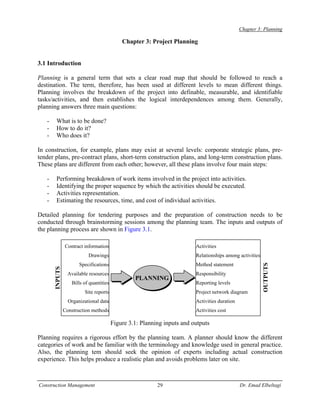
  • 1. Chapter 3: Planning Chapter 3: Project Planning 3.1 Introduction Planning is a general term that sets a clear road map that should be followed to reach a destination. The term, therefore, has been used at different levels to mean different things. Planning involves the breakdown of the project into definable, measurable, and identifiable tasks/activities, and then establishes the logical interdependences among them. Generally, planning answers three main questions: - What is to be done? - How to do it? - Who does it? In construction, for example, plans may exist at several levels: corporate strategic plans, pre- tender plans, pre-contract plans, short-term construction plans, and long-term construction plans. These plans are different from each other; however, all these plans involve four main steps: - Performing breakdown of work items involved in the project into activities. - Identifying the proper sequence by which the activities should be executed. - Activities representation. - Estimating the resources, time, and cost of individual activities. Detailed planning for tendering purposes and the preparation of construction needs to be conducted through brainstorming sessions among the planning team. The inputs and outputs of the planning process are shown in Figure 3.1. Contract information Activities Drawings Relationships among activities Specifications Method statement OUTPUTS INPUTS Available resources Responsibility PLANNING Bills of quantities Reporting levels Site reports Project network diagram Organizational data Activities duration Construction methods Activities cost Figure 3.1: Planning inputs and outputs Planning requires a rigorous effort by the planning team. A planner should know the different categories of work and be familiar with the terminology and knowledge used in general practice. Also, the planning tem should seek the opinion of experts including actual construction experience. This helps produce a realistic plan and avoids problems later on site. Construction Management 29 Dr. Emad Elbeltagi
  • 2. Chapter 3: Planning 3.2 Project Planning Steps The following steps may be used as a guideline, or checklist to develop a project plan: 1. Define the scope of work, method statement, and sequence of work. 2. Generate the work breakdown structure (WBS) to produce a complete list of activities. 3. Develop the organization breakdown structure (OBS) and link it with work breakdown structure o identify responsibilities. 4. Determine the relationship between activities. 5. Estimate activities time duration, cost expenditure, and resource requirement. 6. Develop the project network. 3.2.1 Work breakdown structure (WBS) The WBS is described as a hierarchical structure which is designed to logically sub-divide all the work-elements of the project into a graphical presentation. The full scope of work for the project is placed at the top of the diagram, and then sub-divided smaller elements of work at each lower level of the breakdown. At the lowest level of the WBS the elements of work is called a work package. A list of project’s activities is developed from the work packages. Effective use of the WBS will outline the scope of the project and the responsibility for each work package. There is not necessarily a right or wrong structure because what may be an excellent fit for one discipline may be an awkward burden for another. To visualize the WBS, consider Figure 3.2 which shows a house construction project. House Civil Plumping Electrical Foundations Walls/Roof Piping H/C Water Wiring Fittings Figure 3.2: WBS and their description As shown in Figure 3.2, level 1 represents the full scope of work for the house. In level 2, the project is sub-divided into its three main trades, and in level 3 each trade is sub-divided to specific work packages. Figure 3.3 shows another example for more detailed WBS, in which the project WBS is divided into five levels: Construction Management 30 Dr. Emad Elbeltagi
  • 3. Chapter 3: Planning Level 1 Gas development project Level 2 Recovery unit 300 Process unit 400 Level 3 Train 2 Train 1 Gas treating Separation and stabilization Level 4 Instrumentation Structural steel Civil Piping Piping Level 5 fabrication Figure 3.3: Five levels WBS Level 1: The entire project. Level 2: Independent areas. Level 3: Physically identifiable sections fully contained in a level 2 area, reflect construction strategy. Level 4: Disciplines set up schedule. Level 5: Master schedule activities, quantity, duration. Example 3.1: The WBS for a warehouse is as follow: Foe more details, another two levels (third and fourth levels) can be added as shown below: Construction Management 31 Dr. Emad Elbeltagi
  • 4. Chapter 3: Planning Accordingly, a complete WBS for the warehouse project can be shown as follow (Figure 3.4): Figure 3.4: Warehouse project WBS WBS and organizational breakdown structure (OBS) The WBS elements at various levels can be related to the contractor’s organizational breakdown structure (OBS), which defines the different responsibility levels and their appropriate reporting needs as shown in Figure 3.5. The figure, also, shows that work packages are tied to the company unified code of accounts. The unified code of accounts allows cataloging, sorting, and summarizing of all information. As such, the activity of installing columns formwork of area 2, for example, which is the responsibility of the general contractor’s formwork foreman, has a unique code that represents all its data. WBS coding A project code system provides the framework for project planning and control in which each work package in a WBS is given a unique code that is used in project planning and control. The coding system provides a comprehensive checklist of all items of work that can be found in a specific type of construction. Also, it provides uniformity, transfer & comparison of information among projects. An example of this coding system is the MasterFormat (Figure 3.6) which was developed through a joint effort of 8 industry & professional associations including: Construction Specifications Institute (CSI); and Construction Specifications Canada (CSC). Construction Management 32 Dr. Emad Elbeltagi
  • 5. Chapter 3: Planning Figure 3.7 shows an example of the coding system using a standardize system as the MasterFormat. The Master format is divided into 16 divisions as follows: 1) General Requirements. 2) Site work. 3) Concrete. 4) Masonry. 5) Metals. 6) Woods & Plastics. 7) Thermal & Moisture Protection. 8) Doors & Windows. 9) Finishes. 10) Specialties. 11) Equipment 12) Furnishings. 13) Special Construction. 14) Conveying Systems. 15) Mechanical. 16) Electrical. WBS (Work elements) Project Area 1 Area 2 Area 3 …… Beams Columns Slabs …… superintendent Formwork Reinforcement Concreting …… Electrical Subcontractor OBS (Responsibility & reporting) Concrete foreman B Project manager superintendent Formwork contractor foreman Control account General Civil Subcontractor foreman Rebar superintendent Mechanical A Figure 3.5: WBS linked to the OBS Construction Management 33 Dr. Emad Elbeltagi
  • 6. Chapter 3: Planning CSI – Masterformat (Building Construction) Figure 3.6: MasterFormat coding ssytem Construction Management Construction Management 34 34 Dr. Emad Elbeltagi Dr. Eamd Elbeltagi
  • 7. Chapter 3: Planning Figure 3.7: An example of an activity coding system Project activities The building block (the smallest unit) of a WBS is the activity, which is a unique unit of the project that has a specified duration. An activity is defined as any function or decision in the project that: consumes time, resources, and cost. Activities are classified to three typs: Production activities: activities that involve the use of resources such as labor, equipment, material, or subcontractor. This type of activities can be easily identified by reading the project’s drawings and specifications. Examples are: excavation, formwork, reinforcement, concreting, etc. each production activity can have a certain quantity of work, resource needs, costs, and duration. Procurement activities: activities that specify the time for procuring materials or equipment that are needed for a production activity. Examples are: brick procurement, boiler manufacturing and delivery, etc. Management activities: activities that are related to management decisions such as approvals, vacations, etc. An activity can be as small as “steel fixing of first floor columns” or as large as “construct first floor columns”. This level of details depends on the purpose of preparing the project plan. In the pre construction stages, less detailed activities can be utilized, however, in the construction stages, detailed activities are required. Accordingly, level of details depends on: planning stage, size of the project, complexity of the work, management expertise. Construction Management 35 Dr. Emad Elbeltagi
  • 8. Chapter 3: Planning Example 3.2: Figure 3.8 shows a double-span bridge. Break the construction works of the bridge into activities. The plan will be used for bidding purposes. Hand rail Road base right Road base left Deck slab Precast beams Figure 3.8: Double span bridge A list of the double-span bridge activities is shown in Table 3.1 Table 3.1: Activities of the double-span bridge Activity Description 10 Set-up site 14 Procure reinforcement 16 Procure precast beams 20 Excavate left abutment 30 Excavate right abutment 40 Excavate central pier 50 Foundation left abutment 60 Foundation right abutment 70 Foundation central pier 80 Construct left abutment 90 Construct right abutment 100 Construct central pier 110 Erect left precast beams 120 Erect right precast beams 140 Fill left embankment 150 Fill right embankment 155 Construct deck slab 160 Left road base 170 Right road base 180 Road surface 190 Bridge railing 200 Clear site 3.2.2 Activities relationships In order to identify the relationships among activities, the planning team needs to answer the following questions for each activity in the project: - Which activities must be finished before the current one can start? - What activity(ies) may be constructed concurrently with the current one? Construction Management 36 Dr. Emad Elbeltagi
  • 9. Chapter 3: Planning - What activity(ies) must follow the current one? A circle of activity precedences will result in an impossible plan. For example, if activity A precedes activity B, activity B precedes activity C, and activity C precedes activity A, then the project can never be started or completed. Figure 3.9 illustrates the resulting activity network. Figure 3.9: Example of a circle of activity precedence Example 3.3: Suppose that a site preparation and concrete slab foundation construction project consists of nine different activities: A. Site clearing (of brush and minor debris), B. Removal of trees, C. General excavation, D. Grading general area, E. Excavation for utility trenches, F. Placing formwork and reinforcement for concrete, G. Installing sewer lines, H. Installing other utilities, I. Pouring concrete. Activities A (site clearing) and B (tree removal) do not have preceding activities since they depend on none of the other activities. We assume that activities C (general excavation) and D (general grading) are preceded by activity A (site clearing). It might also be the case that the planner wished to delay any excavation until trees were removed, so that B (tree removal) would be a precedent activity to C (general excavation) and D (general grading). Activities E (trench excavation) and F (concrete preparation) cannot begin until the completion of general excavation and grading, since they involve subsequent excavation and trench preparation. Activities G (install lines) and H (install utilities) represent installation in the utility trenches and cannot be attempted until the trenches are prepared, so that activity E (trench excavation) is a preceding activity. We also assume that the utilities should not be installed until grading is completed to avoid equipment conflicts, so activity D (general grading) is also preceding activities G (install sewers) and H (install utilities). Finally, activity I (pour concrete) cannot begin until the sewer line is installed and formwork and reinforcement are ready, so activities F and G are preceding. Other utilities may be routed over the slab foundation, so activity H (install utilities) is not necessarily a preceding activity for activity I (pour concrete). The result of our planning is the immediate precedence shown in Table 3.2. Construction Management 37 Dr. Emad Elbeltagi
  • 10. Chapter 3: Planning Table 3.2: Precedence relations for Example 3.3 Activity Description Predecessors A Site clearing --- B Removal of trees --- C General excavation A D Grading general area A E Excavation for utility trenches B,C F Placing formwork and reinforcement for concrete B,C G Installing sewer lines D,E H Installing other utilities D,E I Pouring concrete F,G Example 3.4: Determine the relationships between activities of the project studied in Example 3.2. Table 3.3: Solution of Example 3.4 Activity Description Predecessors 10 Set-up site --- 14 Procure RFT --- 16 Procure P.C. Beams --- 20 Excavate left abutment 10 30 Excavate right abutment 10 40 Excavate central pier 10 50 Foundation left abutment 14, 20 60 Foundation right abutment 14, 30 70 Foundation central pier 14, 40 80 Construct left abutment 50 90 Construct right abutment 60 100 Construct central pier 70 110 Erect left P.C. Beams 16, 80, 100 120 Erect right P.C. Beams 16, 90, 100 140 Fill left embankment 80 150 Fill right embankment 90 155 Construct deck slab 110, 120 160 Left road base 140 170 Right road base 150 180 Road surface 155, 160, 170 190 Bridge railing 155 200 Clear site 180, 190 Logical relationship considering resource constraints For efficient use of resources or in case of constrained resources, it might be beneficial to consider the resources when determining the logical relationship among the activities that use the same resources. For example, consider the case of construction a simple project consists of three units and each unit has three sequential activities (logical relationship). Table 3.4 shows the logical relationship among these activities assuming unconstrained (resources are available with Construction Management 38 Dr. Emad Elbeltagi
  • 11. Chapter 3: Planning any quantities) and constrained resources (only one resource unit is available form each resource type). Table 3.4: Logical relationships considering constrained and unconstrained resources Predecessors Predecessors Activity description (unconstrained resources) (constrained resources) A1 Excavate unit 1 - - B1 Concreting unit 1 A1 A1 C1 Brickwork unit 1 B1 B1 A2 Excavate unit 2 - A1 B2 Concreting unit 2 A2 B1, A2 C2 Brickwork unit 2 B2 C1, B2 A3 Excavate unit 3 - A2 B3 Concreting unit 3 A3 B2, A3 C3 Brickwork unit 3 B3 C2, B3 Overlap or lag Overlap between activities (negative lag) is defined as how much a particular activity must be completed before a succeeding activity may start. The absence of overlap means that the first activity must finish before the second may start. A negative overlap (lag) means a delay is required between the two activities (Figure 3.10) +ve overlap (-ve lag) -ve overlap (+ve lag) Figure 3.10: Overlap among activities Example 3.5: This case study is for a small 3 houses project. The main segments of a single house, the responsibilities, and the logical relationship are identified as follows: - 11 work packages are involved: A and B (civil work, substructure), C, D, E, and F (civil work, superstructure), G (electrical, interior), H (electrical, exterior), I (mechanical, HVAC), J (mechanical, elevator), and K (mechanical, plumbing). - Substructure is supervised by Ahmed (activity A), and Ali (activity B). - Superstructure is supervised by Hossam (activities C and F) and Mona (activities D and E). - All electrical work is supervised by George. - HVAC and plumbing are supervised by Adam; elevator work is supervised by Samy. - Activities E and F follow activity B. - Activity C precedes activity G. - Activity I follows the completion of activity E. - The predecessors to activity K are activities H and I. Construction Management 39 Dr. Emad Elbeltagi
  • 12. Chapter 3: Planning - Activity D follows activity A and precedes activity H. - Activity J is preceded by activities F and G. 1. Create a WBS and OBS chart. Solution: From the available information, the relationship table, the network diagrams, and the WBS linked to an OBS are formed as shown below (Table 3.5 and Figure 3.11). Table 3.5: Logical relationships of Example 3.5 Activity Predecessors Start - A Start B Start C Start D A E B F B G C H D I E J F, G K H, I Finish J, K WBS (Work elements) Project Civil Elec. Mech House1 House1 House1 Sub Super Ahmed A OBS (Responsibility & reporting) Ali B G George H Project manager C Hossam F D Mona E I Adam K Samy J Figure 3.11: WBS and OBS of Example 3.5 Construction Management 40 Dr. Emad Elbeltagi
  • 13. Chapter 3: Planning Types of activities relationships Four types of relationships among activities can be defined as described and illustrated below (Figure 3.12). Typically, relationships are defined from the predecessor to the successor activity. a) Finish to start (FS). The successor activity can begin only when the current activity completes. b) Finish to finish (FF). The finish of the successor activity depends on the finish of the current activity. c) Start to start (SS). The start of the successor activity depends on the start of the current activity. d) Start to finish (SF). The successor activity cannot finish until the current activity starts. a b c d Figure 3.12: Types of relationships 3.2.3 Drawing the project network A network is a graphical representation of the project activities and their relationships. A project network is a set of arrows and nodes. Before drawing the network, it is necessary to ensure that the project has a unified starting and ending point. The need for this start activity arises when there is more than one activity in the project that has no predecessors and the end activity is needed when there is more than one activity that has no successors. Also, networks should be continuous (i.e., each activity except the first and the last has both preceding and succeeding activities). There are two ways that are commonly used to draw a network diagram for a project: 1. Activity on Arrow (AOA) representation. 2. Activity on Node (AON) representation 3.2.3.1 Activity on arrow network (AOA) In this method, the arrows represent activities while the nodes represent the start and the end of an activity (usually named as events) (Figure 3.13). The length of the arrow connecting the nodes Construction Management 41 Dr. Emad Elbeltagi
  • 14. Chapter 3: Planning has no significance and may be straight, curved, or bent. When one activity depends upon another, both appear on the diagram as two arrows having a common node. Activity A Activity B i j j>i 5 10 A B 5 10 15 B depends on A A C 5 10 15 C depends on A and B B 5 15 B B depends on A C depends on A A C 5 10 15 5 15 A C B depends on A and B D depends on A and B B 10 D 5 15 Figure 3.13: Basic patterns of AOA diagrams The following are some rules that need to be followed when constructing an AOA network diagram: - Each activity must have a unique i – j numbers, where i (the number at the tail of the arrow) is smaller than j (the number at the head of the arrow). - It is recommended to have a gap between numbers (i.e., 5, 10, 15, etc.). This will allow for accommodation of missed activities. - Avoid back arrows. In some situations, when more than one arrow leave the same node and arrive at another node, dummy activities must be used. The dummy activity is an activity with zero duration, consumes no resources, drawn as dashed lines, and used to adjust the network diagram. A dummy activity is also used when one activity depends upon two preceding activities and another activity depends only upon one of these two preceding activities as shown in Figure 3.14. 3.2.3.2 Activity on node network (AON) This method is also called the precedence diagram method. In this method, the nodes represent activities and the arrows represent logical relationships among the activities. If the arrow starts from the end side of an activity (activity A) and ends at the start side of another activity (activity Construction Management 42 Dr. Emad Elbeltagi
  • 15. Chapter 3: Planning B), then A is a predecessor of B (Figure 3.15). AON representation allows the overlap or lag representation on the relationship arrows connecting activities. A C A C 5 15 20 5 20 25 D C depends on A and B B Dummy D depends on B only 25 B D 10 10 15 30 A A 5 15 5 15 B Dummy B 10 Incorrect representation Correct representation Figure 3.14: Use of dummy activity 10 Activity number 20 A B Activity name 10 20 B depends on A A B 10 30 40 C depends on A and B A C D D depends on C 20 B 30 C 10 20 B depends on A A B C depends on B D depends on B 40 D Figure 3.15: Basic patterns of AON diagrams Construction Management 43 Dr. Emad Elbeltagi
  • 16. Chapter 3: Planning Comparison between AOA and AON While both networks can be used to represent a project network, there are some differences between them: - There is no need for the use of dummy activities in AON representation. - AON are more easily to draw and to read. - In AOA, an activity can only start when all its predecessors have finished. - AON allows for overlap/lag representation. - AON allows for the representation of the four types of relationships while AOA allows only for the finish to start relationship. Example 3.6: Construct an AOA and AON networks for the activities listed in Table 3.6. Table 3.6 Data for Example 3.6 Activity Predecessors A - B - C A, B D C E C F D G D, E Forming an AOA network for this set of activities might begin be drawing activities A, B and C as shown in Figure 3.16 (a). At this point, we note that two activities (A and B) lie between the same two event nodes; for clarity, we insert a dummy activity X and continue to place other activities as in Figure 3.16 (b). Placing activity G in the figure presents a problem, however, since we wish both activity D and activity E to be predecessors. Inserting an additional dummy activity Y along with activity G completes the activity network, as shown in Figure 3.16 (c). Figure 3.16: AOA Network for Example 3.6 Construction Management 44 Dr. Emad Elbeltagi
  • 17. Chapter 3: Planning To understand the drawing of the AON, some ordering for the activities may be necessary. This is done by placing the activities in a sequence step order. A sequence step may be defined as the earliest logical position in the network that an activity can occupy while maintaining the logical relationships. In this example, as there are two activities (activities A and B) has no predecessor, then a start activity is added to have one unified start activity (Start) for the project. Also, a finish activity (Finish) is added as there are two activities without successors (activities F and G). Considering the data given in Table 3.6, sequence step 1 is assigned to the Start activity. Then, we take all activities on the list one by one and look at their immediate predecessors and then assign a sequence step that equals the highest sequence step of all immediate predecessors plus one as given in Table 3.7. After all sequence step numbers have been assigned, the AON diagram can be drawn. Table 3.7: Determining the sequence steps Activity Predecessors Sequence step (SS) Start - SS(Start)=1 A Start 2=SS(Start)+1 B Start 2=SS(Start)+1 C A, B 3=Highest of [SS(B), SS(A)] D C 4=SS(C)+1 E C 4=SS(C)+1 F D 5=SS(D)+1 G D, E 5=Highest of [SS(D), SS(E)] Finish F, G 6= Highest of [SS(F), SS(G)] Sequence step 1 2 3 4 5 6 Figure 3.17: An AON Network AON representation is shown in Figure 3.17, including project start and finish nodes. Note that dummy activities are not required for expressing precedence relationships in activity-on-node networks. Construction Management 45 Dr. Emad Elbeltagi
  • 18. Chapter 3: Planning Example 3.7: Draw the AOA and AON networks for the project given in Example 3.5. Solution The AOA is given in Figure 3.18 and the AON is given in Figure 3.19 as shown below. D 10 25 A H B E I K 5 15 30 40 45 F C J G 20 35 Figure 3.18: AOA network A D H K Start B E I Finish F J C G Figure 3.19: AON network Construction Management 46 Dr. Emad Elbeltagi
  • 19. Chapter 3: Planning 3.3 Estimating Activity Duration and Direct Cost Having defined the work activities, each activity has associated time duration. These durations are used in preparing a schedule. For example, suppose that the durations shown in Table 3.8 were estimated for a project. The entire set of activities would then require at least 3 days, since the activities follow one another directly and require a total of 1.0 + 0.5 + 0.5 + 1.0 = 3 days. Table 3.8: Durations and predecessors for a four-activity project Activity Predecessor Duration (Days) Excavate trench --- 1.0 Place formwork Excavate trench 0.5 Place reinforcing Place formwork 0.5 Pour concrete Place reinforcing 1.0 All scheduling procedures rely upon estimates of the durations of the various project activities as well as the definitions of the predecessor relationships among activities. A straightforward approach to the estimation of activity durations is to keep historical records of particular activities and rely on the average durations from this experience in making new duration estimates. Since the scope of activities is unlikely to be identical between different projects, unit productivity rates are typically employed for this purpose. The duration of an activity may be estimated as: Activity duration = quantity of work / number of crews x resource output Typically, the quantity of work is determined from engineering drawings of a specific project. The number of crews working is decided by the planner. In many cases, the number or amount of resources applied to particular activities may be modified in light of the resulting project plan and schedule. Some estimate of the expected work productivity must be provided. Historical records in a firm can also provide data for estimation of productivities. Having defined an activity duration, it means that the planner have already defined the number of resources that will be employed in a particular activity. Knowing activity duration and resources employed, it is simple to estimate the activity direct cost. Then, the three elements of an activity: duration, cost, and resources form what is called construction method. Some activities can be performed using different construction methods. Where, its method will have its own resources, cost and duration. Example 3.8: If the daily production rate for a crew that works in an activity is 175 units/day and the total crew cost per day is LE 1800. The material needed for daily work is 4.5 units at LE 100/unit. a. Calculate the time and cost it takes the crew to finish 1400 units b. Calculate the total unit cost. Consider an eight hour work day. Construction Management 47 Dr. Emad Elbeltagi
  • 20. Chapter 3: Planning Solution a. Duration (units of time) = Quantity / Production per unit of time x number of crews = 1400 / 175 x 1 = 8 days Cost (labor cost) = Duration (units of time) x crew cost per unit of time = 8 days x LE 1800 / day = LE 14400 Total direct cost = Le 14400 + 4.5 units of material x LE 100 / day x 8 days = LE 18000 b. Unit cost = total cost / quantity = LE 18000 / 1400 = LE 12.86 / unit Sometimes the productivity of a specific crew expressed in man-hours/unit not units/day. For example, if the productivity is said to be 0.5 Man-hour/cubic meters, this means how long it will take one labor to construct one unit. This way applied to any crew formation and work hours. Example 3.9: What is the duration in days to install 6000 square feet of walls shuttering if: a. Crew of 2 carpenters is used with output of 200 square feet/day b. Productivity is measured as 0.008 man-hour/square feet. Number of carpenters =3, and number of working hours/day = 8 hours Solution a. Duration = 6000 / 200 = 3 days b. Total man-hours needed = 6000 x 0.008 = 48 man-hours (if one man used) Duration = 48 / 8 = 6 days (if one man used) Duration using 3 men = 6 / 3 = 2 days Example 3.10: (use of several resources) The construction of a reinforced concrete wall involves placing 660 m3 concrete, fixing 50 tone of steel, and 790 m2 of formwork. The following information belongs to the jobs involved in this activity: - A 6 man concrete crew can place 16 m3 of concrete/day. - A steel-fixer and assistant can fix 0.5 ton of reinforcement/day. - A carpenter and assistant can fix and remove 16 m2 of shuttering/day. Calculate the duration of the activity considering the steel-fixer as the critical resource. Solution - using one steel-fixer: duration = 50 / 0.5 = 100 days - using one carpenter: duration = 790 / 16 = 49.4 days - using one concreting crew: duration = 660 / 16 = 41.25 days. Then, for a balanced mix of resources, use 2 steel-fixer crews, one carpenter crew, and cone concreting crew. Accordingly, the activity duration = 50 / 0.5 x 2 = 50 days. Construction Management 48 Dr. Emad Elbeltagi