SlideShare una empresa de Scribd logo
1 de 114
Descargar para leer sin conexión
OIL PUMP FRONT SEAL
REMOVAL . . . . . . . . . . . . . . . . . . . . . . . . . . . . 436
INSTALLATION . . . . . . . . . . . . . . . . . . . . . . . . 436
OUTPUT SPEED SENSOR
DESCRIPTION . . . . . . . . . . . . . . . . . . . . . . . . 436
OPERATION . . . . . . . . . . . . . . . . . . . . . . . . . . 436
REMOVAL . . . . . . . . . . . . . . . . . . . . . . . . . . . . 436
INSTALLATION . . . . . . . . . . . . . . . . . . . . . . . . 437
TOW/HAUL OVERDRIVE SWITCH
DESCRIPTION . . . . . . . . . . . . . . . . . . . . . . . . 437
OPERATION . . . . . . . . . . . . . . . . . . . . . . . . . . 437
REMOVAL . . . . . . . . . . . . . . . . . . . . . . . . . . . . 437
INSTALLATION . . . . . . . . . . . . . . . . . . . . . . . . 438
PISTONS
DESCRIPTION . . . . . . . . . . . . . . . . . . . . . . . . 438
OPERATION . . . . . . . . . . . . . . . . . . . . . . . . . . 438
PLANETARY GEARTRAIN
DESCRIPTION . . . . . . . . . . . . . . . . . . . . . . . . 440
OPERATION . . . . . . . . . . . . . . . . . . . . . . . . . . 441
DISASSEMBLY . . . . . . . . . . . . . . . . . . . . . . . . 442
CLEANING . . . . . . . . . . . . . . . . . . . . . . . . . . . 442
INSPECTION . . . . . . . . . . . . . . . . . . . . . . . . . 442
ASSEMBLY . . . . . . . . . . . . . . . . . . . . . . . . . . . 443
SHIFT MECHANISM
DESCRIPTION . . . . . . . . . . . . . . . . . . . . . . . . 444
OPERATION . . . . . . . . . . . . . . . . . . . . . . . . . . 444
SOLENOID SWITCH VALVE
DESCRIPTION . . . . . . . . . . . . . . . . . . . . . . . . 444
OPERATION . . . . . . . . . . . . . . . . . . . . . . . . . . 444
SOLENOIDS
DESCRIPTION . . . . . . . . . . . . . . . . . . . . . . . . 444
OPERATION . . . . . . . . . . . . . . . . . . . . . . . . . . 445
TORQUE CONVERTER
DESCRIPTION . . . . . . . . . . . . . . . . . . . . . . . . 445
OPERATION . . . . . . . . . . . . . . . . . . . . . . . . . . 449
REMOVAL . . . . . . . . . . . . . . . . . . . . . . . . . . . . 450
INSTALLATION . . . . . . . . . . . . . . . . . . . . . . . . 451
TRANSMISSION CONTROL RELAY
DESCRIPTION . . . . . . . . . . . . . . . . . . . . . . . . 451
OPERATION . . . . . . . . . . . . . . . . . . . . . . . . . . 451
TRANSMISSION RANGE SENSOR
DESCRIPTION . . . . . . . . . . . . . . . . . . . . . . . . 451
OPERATION . . . . . . . . . . . . . . . . . . . . . . . . . . 451
TRANSMISSION SOLENOID/TRS ASSEMBLY
DESCRIPTION . . . . . . . . . . . . . . . . . . . . . . . . 452
OPERATION . . . . . . . . . . . . . . . . . . . . . . . . . . 452
REMOVAL . . . . . . . . . . . . . . . . . . . . . . . . . . . . 453
INSTALLATION . . . . . . . . . . . . . . . . . . . . . . . . 454
TRANSMISSION TEMPERATURE SENSOR
DESCRIPTION . . . . . . . . . . . . . . . . . . . . . . . . 454
OPERATION . . . . . . . . . . . . . . . . . . . . . . . . . . 454
VALVE BODY
DESCRIPTION . . . . . . . . . . . . . . . . . . . . . . . . 454
OPERATION . . . . . . . . . . . . . . . . . . . . . . . . . . 454
REMOVAL . . . . . . . . . . . . . . . . . . . . . . . . . . . . 456
DISASSEMBLY . . . . . . . . . . . . . . . . . . . . . . . . 457
CLEANING . . . . . . . . . . . . . . . . . . . . . . . . . . . 459
INSPECTION . . . . . . . . . . . . . . . . . . . . . . . . . 460
ASSEMBLY . . . . . . . . . . . . . . . . . . . . . . . . . . . 461
INSTALLATION . . . . . . . . . . . . . . . . . . . . . . . . 463
AUTOMATIC TRANSMISSION -
45RFE/545RFE
DESCRIPTION
The 45RFE/545RFE automatic transmissions is a
sophisticated, multi-range, electronically controlled
transmission which combines optimized gear ratios
for responsive performance, state of the art efficiency
features and low NVH. Other features include driver
adaptive shifting and three planetary gear sets to
provide wide ratio capability with precise ratio steps
for optimum driveability. The three planetary gear
sets also make available a unique alternate second
gear ratio. The primary 2nd gear ratio fits between
1st and 3rd gears for normal through-gear accelera-
tions. The alternate second gear ratio (2prime) allows
smoother 4-2 kickdowns at high speeds to provide
2nd gear passing performance over a wider highway
cruising range.
The hydraulic portion of the transmission consists
of the transmission fluid, fluid passages, hydraulic
valves, and various line pressure control components.
The primary mechanical components of the trans-
mission consist of the following:
• Three multiple disc input clutches
• Three multiple disc holding clutches
• Five hydraulic accumulators
• Three planetary gear sets
• Dual Stage Hydraulic oil pump
• Valve body
• Solenoid pack
The TCM is the “heart” or “brain” of the electronic
control system and relies on information from vari-
ous direct and indirect inputs (sensors, switches, etc.)
to determine driver demand and vehicle operating
conditions. With this information, the TCM can cal-
culate and perform timely and quality shifts through
various output or control devices (solenoid pack,
transmission control relay, etc.).
21 - 350 AUTOMATIC TRANSMISSION - 45RFE/545RFE DR
TRANSMISSION IDENTIFICATION
Transmission identification numbers are stamped
on the left side of the case just above the oil pan
sealing surface (Fig. 1). Refer to this information
when ordering replacement parts. A label is attached
to the transmission case above the stamped numbers.
The label gives additional information which may
also be necessary for identification purposes.
GEAR RATIOS
The 45RFE gear ratios are:
1st . . . . . . . . . . . . . . . . . . . . . . . . . . . . . . . . . 3.00:1
2nd . . . . . . . . . . . . . . . . . . . . . . . . . . . . . . . . . 1.67:1
2nd Prime . . . . . . . . . . . . . . . . . . . . . . . . . . . 1.50:1
3rd . . . . . . . . . . . . . . . . . . . . . . . . . . . . . . . . . 1.00:1
4th . . . . . . . . . . . . . . . . . . . . . . . . . . . . . . . . . 0.75:1
Reverse . . . . . . . . . . . . . . . . . . . . . . . . . . . . . 3.00:1
GEAR RATIOS
The 545RFE gear ratios are:
1st . . . . . . . . . . . . . . . . . . . . . . . . . . . . . . . . . 3.00:1
2nd . . . . . . . . . . . . . . . . . . . . . . . . . . . . . . . . . 1.67:1
2nd Prime . . . . . . . . . . . . . . . . . . . . . . . . . . . 1.50:1
3rd . . . . . . . . . . . . . . . . . . . . . . . . . . . . . . . . . 1.00:1
4th . . . . . . . . . . . . . . . . . . . . . . . . . . . . . . . . . 0.75:1
5th . . . . . . . . . . . . . . . . . . . . . . . . . . . . . . . . . 0.67:1
Reverse . . . . . . . . . . . . . . . . . . . . . . . . . . . . . 3.00:1
OPERATION
The 45RFE/545RFE offers full electronic control of
all automatic up and downshifts, and features real-
time adaptive closed-loop shift and pressure control.
Electronic shift and torque converter clutch controls
help protect the transmission from damage due to
high temperatures, which can occur under severe
operating conditions. By altering shift schedules, line
pressure, and converter clutch control, these controls
reduce heat generation and increase transmission
cooling.
To help reduce efficiency-robbing parasitic losses,
the transmissions includes a dual-stage transmission
fluid pump with electronic output pressure control.
Under most driving conditions, pump output pres-
sure greatly exceeds that which is needed to keep the
clutches applied. The 45RFE/545RFE pump-pressure
control system monitors input torque and adjusts the
pump pressure accordingly. The primary stage of the
pump works continuously; the second stage is
bypassed when demand is low. The control system
also monitors input and output speed and, if incipi-
ent clutch slip is observed, the pressure control sole-
noid duty cycle is varied, increasing pressure in
proportion to demand.
A high-travel torque converter damper assembly
allows earlier torque converter clutch engagement to
reduce slippage. Needle-type thrust bearings reduce
internal friction. The 45RFE/545RFE is packaged in
a one-piece die-cast aluminum case. To reduce NVH,
the case has high lateral, vertical and torsional stiff-
ness. It is also designed to maximize the benefit of
the structural dust cover that connects the bottom of
the bell housing to the engine bedplate, enhancing
overall power train stiffness. Dual filters protect the
pump and other components. A pump return filter is
added to the customary main sump filter. Indepen-
dent lubrication and cooler circuits assure ample
pressure for normal transmission operation even if
the cooler is obstructed or the fluid cannot flow due
to extremely low temperatures.
The hydraulic control system design (without elec-
tronic assist) provides the transmission with PARK,
REVERSE, NEUTRAL, SECOND, and THIRD gears,
based solely on driver shift lever selection. This
design allows the vehicle to be driven (in “limp-in”
mode) in the event of a electronic control system fail-
ure, or a situation that the Transmission Control
Module (TCM) recognizes as potentially damaging to
the transmission.
The TCM also performs certain self-diagnostic
functions and provides comprehensive information
(sensor data, DTC’s, etc.) which is helpful in proper
diagnosis and repair. This information can be viewed
with the DRB௡ scan tool.
Fig. 1 Transmission Part And Serial Number
Location
1 - IDENTIFICATION NUMBERS (STAMPED)
DR AUTOMATIC TRANSMISSION - 45RFE/545RFE 21 - 351
AUTOMATIC TRANSMISSION - 45RFE/545RFE (Continued)
DIAGNOSIS AND TESTING
DIAGNOSIS AND TESTING - AUTOMATIC
TRANSMISSION
CAUTION: Before attempting any repair on a RFE
automatic transmission, check for Diagnostic Trou-
ble Codes with the DRBா scan tool.
Transmission malfunctions may be caused by these
general conditions:
• Poor engine performance
• Improper adjustments
• Hydraulic malfunctions
• Mechanical malfunctions
• Electronic malfunctions
Diagnosis of these problems should always begin
by checking the easily accessible variables: fluid level
and condition, gearshift cable adjustment. Then per-
form a road test to determine if the problem has been
corrected or if more diagnosis is necessary. If the
problem persists after the preliminary tests and cor-
rections are completed, hydraulic pressure checks
should be performed.
DIAGNOSIS AND TESTING - PRELIMINARY
Two basic procedures are required. One procedure
for vehicles that are drivable and an alternate proce-
dure for disabled vehicles (will not back up or move
forward).
VEHICLE IS DRIVABLE
(1) Check for transmission fault codes using DRB௡
scan tool.
(2) Check fluid level and condition.
(3) Adjust gearshift cable if complaint was based
on delayed, erratic, or harsh shifts.
(4) Road test and note how transmission upshifts,
downshifts, and engages.
(5) Perform hydraulic pressure test if shift prob-
lems were noted during road test.
(6) Perform air-pressure test to check clutch oper-
ation.
VEHICLE IS DISABLED
(1) Check fluid level and condition.
(2) Check for broken or disconnected gearshift
cable.
(3) Check for cracked, leaking cooler lines, or loose
or missing pressure-port plugs.
(4) Raise and support vehicle on safety stands,
start engine, shift transmission into gear, and note
following:
(a) If propeller shaft turns but wheels do not,
problem is with differential or axle shafts.
(b) If propeller shaft does not turn and transmis-
sion is noisy, stop engine. Remove oil pan, and
check for debris. If pan is clear, remove transmis-
sion and check for damaged driveplate, converter,
oil pump, or input shaft.
(c) If propeller shaft does not turn and transmis-
sion is not noisy, perform hydraulic-pressure test to
determine if problem is hydraulic or mechanical.
DIAGNOSIS AND TESTING - ROAD TESTING
Before road testing, be sure the fluid level and con-
trol cable adjustments have been checked and
adjusted if necessary. Verify that all diagnostic trou-
ble codes have been resolved.
Observe engine performance during the road test.
A poorly tuned engine will not allow accurate analy-
sis of transmission operation.
Operate the transmission in all gear ranges. Check
for shift variations and engine flare which indicates
slippage. Note if shifts are harsh, spongy, delayed,
early, or if part throttle downshifts are sensitive.
Slippage indicated by engine flare, usually means
clutch, overrunning clutch, or line pressure problems.
A slipping clutch can often be determined by com-
paring which internal units are applied in the vari-
ous gear ranges. The Clutch Application charts
provide a basis for analyzing road test results.
21 - 352 AUTOMATIC TRANSMISSION - 45RFE/545RFE DR
AUTOMATIC TRANSMISSION - 45RFE/545RFE (Continued)
45RFE CLUTCH APPLICATION CHART
SLP UD OD R 2C 4C L/R OVERRUNNING
P–PARK ON
R–REVERSE ON ON
N-NEUTRAL ON
D–OVERDRIVE
FIRST
ON ON* ON
SECOND ON ON
SECOND PRIME ON ON
THIRD ON ON
FOURTH ON ON
LIMP-IN ON ON
2–FIRST ON ON* ON
SECOND ON ON
LIMP-IN ON ON
1–LOW ON ON ON
*L/R clutch is on only with the output shaft speed below 150 rpm.
545RFE CLUTCH APPLICATION CHART
SLP UD OD R 2C 4C L/R OVERRUNNING
P–PARK ON
R–REVERSE ON ON
N-NEUTRAL ON
D–OVERDRIVE
FIRST
ON ON* ON
SECOND ON ON
SECOND PRIME ON ON
THIRD ON ON
FOURTH ON ON
FIFTH ON ON
LIMP-IN ON ON
2–FIRST ON ON* ON
SECOND ON ON
LIMP-IN ON ON
1–LOW ON ON ON
*L/R clutch is on only with the output shaft speed below 150 rpm.
DR AUTOMATIC TRANSMISSION - 45RFE/545RFE 21 - 353
AUTOMATIC TRANSMISSION - 45RFE/545RFE (Continued)
DIAGNOSIS AND TESTING - HYDRAULIC
PRESSURE TEST
An accurate tachometer and pressure test gauges
are required. Test Gauge C-3293-SP has a 300 psi
range and is used at all locations where pressures
exceed 100 psi.
Pressure Test Port Locations
Only two pressure ports are supplied on the trans-
mission case. The torque converter clutch apply and
release ports are located on the right side of the
transmission case (Fig. 2).
To determine the line pressure, there are two avail-
able methods. The DRB௡ scan tool can be used to
read line pressure from the line pressure sensor. The
second method is to install Line Pressure Adapter
8259 (Fig. 4) into the transmission case and then
install the pressure gauge and the original sensor
into the adapter. This will allow a comparison of the
DRB௡ readings and the gauge reading to determine
the accuracy of the line pressure sensor. The DRB௡
line pressure reading should match the gauge read-
ing within ±10 psi.
In order to access any other pressure tap locations,
the transmission oil pan must be removed, the pres-
sure port plugs removed and Valve Body Pressure
Tap Adapter 8258-A (Fig. 5) installed. The extensions
supplied with Adapter 8258-A will allow the installa-
tion of pressure gauges to the valve body. Refer to
(Fig. 3) for correct pressure tap location identifica-
tion.
Fig. 2 Torque Converter Pressure Locations
1 - TCC RELEASE
2 - TO COOLER
3 - TCC APPLY
4 - FROM COOLER
5 - LINE PRESSURE SENSOR
Fig. 3 Pressure Tap Locations
Fig. 4 Line Pressure Adapter 8259
1 - LINE PRESSURE SENSOR PORT
2 - LINE PRESSURE SENSOR
3 - TOOL 8259
4 - PRESSURE TAP
21 - 354 AUTOMATIC TRANSMISSION - 45RFE/545RFE DR
AUTOMATIC TRANSMISSION - 45RFE/545RFE (Continued)
TEST PROCEDURE
All pressure readings should be taken with the
transmission fluid level full, transmission oil at the
normal operating temperature, and the engine at
1500 rpm. Check the transmission for proper opera-
tion in each gear position that is in question or if a
specific element is in question, check the pressure
readings in at least two gear positions that employ
that element. Refer to the Hydraulic Schematics at
the rear of this section to determine the correct pres-
sures for each element in a given gear position.
NOTE: The 45RFE/545RFE utilizes closed loop con-
trol of pump line pressure. The pressure readings
may therefore vary greatly but should always follow
line pressure.
Some common pressures that can be measured to
evaluate pump and clutch performance are the
upshift/downshift pressures, garage shift pressures,
and TCC pressure. The upshift/downshift pressure
for all shifts are shown in UPSHIFT PRESSURES
and DOWNSHIFT PRESSURES. In-gear maximum
pressure for each gear position is shown in IN-GEAR
PRESSURES. The garage shift pressure when per-
forming a N-R shift is 220 psi for 3.7L/4.7L equipped
vehicles and 250 psi for 5.7L equipped vehicles. The
garage shift pressure for the R-N shift is 120 psi. The
garage shift pressure for the N-1 shift is 135 psi for
3.7L/4.7L equipped vehicles and 165 psi for 5.7L
equipped vehicles. Torque converter lock-up pressure
is 120 psi for 3.7L/4.7L equipped vehicles and 125 psi
for 5.7L equipped vehicles.
UPSHIFT PRESSURES
ENGINE 1-2 2-3 2prime-3 3-4 2prime-4 2-5 3-5 4-5
5.7L 150 125 125 135 135 135 135 135
3.7L/4.7L 120 120 120 120 120 120 120 130
DOWNSHIFT PRESSURES
ENGINE 5-4 5-3 5-2 4-3 4-
2prime
3-2 3-
2prime
2prime-1 2-1 3-1
5.7L 135 135 135 135 135 135 135 135 135 135
3.7L/
4.7L
120 120 120 120 120 120 120 120 120 120
IN-GEAR PRESSURES
ENGINE 1 2 2prime 3 4 5 NEUTRAL REVERSE
5.7L 160 135 135 135 135 135 120 250
3.7L/4.7L 135 120 120 120 120 120 120 220
Fig. 5 Valve Body Pressure Tap Adapter 8258-A
1 - RFE TRANSMISSION
2 - TOOL 8258-A
DR AUTOMATIC TRANSMISSION - 45RFE/545RFE 21 - 355
AUTOMATIC TRANSMISSION - 45RFE/545RFE (Continued)
DIAGNOSIS AND TESTING - AIR CHECKING
TRANSMISSION CLUTCH OPERATION
Air-pressure testing can be used to check transmis-
sion clutch operation. The test can be conducted with
the transmission either in the vehicle or on the work
bench, as a final check.
Air-pressure testing requires that the oil pan and
valve body be removed from the transmission. The
clutch apply passages are shown in the Air Pressure
Test Passages graphic (Fig. 6).
NOTE: The air supply which is used must be free of
moisture and dirt. Use a pressure of 30 psi to test
clutch operation.
Apply air pressure at each port. If the clutch is
functioning, a soft thump will be heard as the clutch
is applied. The clutch application can also be felt by
touching the appropriate element while applying air
pressure. As the air pressure is released, the clutch
should also release.
DIAGNOSIS AND TESTING - CONVERTER
HOUSING FLUID LEAK
When diagnosing converter housing fluid leaks,
two items must be established before repair.
(1) Verify that a leak condition actually exists.
(2) Determined the true source of the leak.
Some suspected converter housing fluid leaks may
not be leaks at all. They may only be the result of
residual fluid in the converter housing, or excess
fluid spilled during factory fill or fill after repair.
Converter housing leaks have several potential
sources. Through careful observation, a leak source
can be identified before removing the transmission
for repair. Torque converter seal leaks tend to move
along the drive hub and onto the rear of the con-
verter. Pump cover seal tend to run down the cover
and the inside surface of the bellhousing.
Some leaks, or suspected leaks, may be particu-
larly difficult to locate. If necessary, a Mopar௡
approved dye may be used to locate a leak.
TORQUE CONVERTER LEAK POINTS
Possible sources of converter leaks are:
(1) Leaks at the weld joint around the outside
diameter weld (Fig. 7).
(2) Leaks at the converter hub weld (Fig. 7).
STANDARD PROCEDURE - ALUMINUM
THREAD REPAIR
Damaged or worn threads in the aluminum trans-
mission case and valve body can be repaired by the
use of Heli-Coils™, or equivalent. This repair con-
sists of drilling out the worn-out damaged threads.
Then tap the hole with a special Heli-Coil™ tap, or
equivalent, and installing a Heli-Coil™ insert, or
equivalent, into the hole. This brings the hole back to
its original thread size.
Heli-Coil™, or equivalent, tools and inserts are
readily available from most automotive parts suppli-
ers.
Fig. 6 Air Pressure Test Passages
1 - LOW REVERSE CLUTCH
2 - 4TH CLUTCH
3 - 2ND CLUTCH
4 - OVERDRIVE CLUTCH
5 - UNDERDRIVE CLUTCH
6 - REVERSE CLUTCH
Fig. 7 Torque Converter Assembly
1 - TURBINE ASSEMBLY
2 - STATOR
3 - CONVERTER HUB
4 - O-RING
5 - IMPELLER ASSEMBLY
6 - CONVERTER CLUTCH PISTON
7 - TURBINE HUB
21 - 356 AUTOMATIC TRANSMISSION - 45RFE/545RFE DR
AUTOMATIC TRANSMISSION - 45RFE/545RFE (Continued)
REMOVAL
(1) Disconnect the negative battery cable.
(2) Raise and support the vehicle
(3) Remove any necessary skid plates. (Refer to 13
- FRAMES & BUMPERS/FRAME/TRANSFER CASE
SKID PLATE - REMOVAL)
(4) Mark propeller shaft and axle companion
flanges for assembly alignment.
(5) Remove the rear propeller shaft
(6) Remove the front propeller shaft, if necessary.
(7) Remove the engine to transmission collar (Fig.
8).
(8) Remove the exhaust support bracket from the
rear of the transmission.
(9) Disconnect and lower or remove any necessary
exhaust components.
(10) Remove the starter motor.
(11) Rotate crankshaft in clockwise direction until
converter bolts are accessible. Then remove bolts one
at a time. Rotate crankshaft with socket wrench on
dampener bolt.
(12) Disengage the output speed sensor connector
from the output speed sensor (Fig. 9).
(13) Disengage the input speed sensor connector
from the input speed sensor (Fig. 10).
(14) Disengage the transmission solenoid/TRS
assembly connector from the transmission solenoid/
TRS assembly (Fig. 11).
(15) Disengage the line pressure sensor connector
from the line pressure sensor (Fig. 12).
(16) Disconnect gearshift cable from transmission
manual valve lever (Fig. 13).
(17) Disconnect the transmission vent hose from
the transmission.
(18) Support rear of engine with safety stand or
jack.
(19) Raise transmission slightly with service jack
to relieve load on crossmember and supports.
(20) Remove bolts securing rear support and cush-
ion to transmission and crossmember.
(21) Remove transfer case, if necessary.
(22) Disconnect transmission fluid cooler lines at
transmission fittings and clips.
(23) Remove all remaining converter housing bolts.
(24) Carefully work transmission and torque con-
verter assembly rearward off engine block dowels.
Fig. 8 Transmission Collar
1 - ENGINE
2 - STRUCTURAL DUST COVER
3 - TRANSMISSION
Fig. 9 Disconnect Output Speed Sensor
1 - TRANSMISSION
2 - OUTPUT SPEED SENSOR
Fig. 10 Disconnect Input Speed Sensor
1 - TRANSMISSION
2 - INPUT SPEED SENSOR
DR AUTOMATIC TRANSMISSION - 45RFE/545RFE 21 - 357
AUTOMATIC TRANSMISSION - 45RFE/545RFE (Continued)
(25) Hold torque converter in place during trans-
mission removal.
(26) Lower transmission and remove (Fig. 14)
assembly from under the vehicle.
(27) To remove torque converter, carefully slide
torque converter out of the transmission.
Fig. 11 Disconnect Transmission Solenoid/TRS
Assembly
1 - TRANSMISSION
2 - TRANSMISSION SOLENOID/TRS ASSEMBLY
Fig. 12 Disconnect Line Pressure Sensor
1 - TRANSMISSION
2 - LINE PRESSURE SENSOR
Fig. 13 Gearshift Cable at Transmission - RFE
1 - GEARSHIFT CABLE
2 - RFE TRANSMISSION
3 - MANUAL LEVER
Fig. 14 Remove Transmission
1 - ENGINE
2 - TRANSMISSION
21 - 358 AUTOMATIC TRANSMISSION - 45RFE/545RFE DR
AUTOMATIC TRANSMISSION - 45RFE/545RFE (Continued)
DISASSEMBLY
(1) Drain fluid from transmission.
(2) Clean exterior of transmission with suitable
solvent or pressure washer.
(3) Remove the torque converter from the trans-
mission.
(4) Remove the manual shift lever (1) (Fig. 15)
from the transmission.
(5) Remove the input (3), output (1), and line pres-
sure sensors (2) from the transmission case. (Fig. 16)
(6) Inspect the ends of the sensors for debris,
which may indicate the nature of the transmission
failure.
(7) Install Support Stand 8257 (1) onto the trans-
mission case. (Fig. 17)
(8) Using Adapter 8266-1 from End-Play Tool Set
8266 (1) and Dial Indicator C-3339 (2), measure and
record the input shaft end-play. (Fig. 18)
Fig. 15 Remove the Manual Shaft Lever
1 - MANUAL SHAFT LEVER
Fig. 16 Remove Input, Output, and Line Pressure
Sensors
1 - OUTPUT SPEED SENSOR
2 - LINE PRESSURE SENSOR
3 - INPUT SPEED SENSOR
Fig. 17 Install Support Stand - Tool 8257
1 - TOOL 8257
Fig. 18 Measure Input Shaft End Play
1 - TOOL 8266
2 - TOOL C-3339
DR AUTOMATIC TRANSMISSION - 45RFE/545RFE 21 - 359
AUTOMATIC TRANSMISSION - 45RFE/545RFE (Continued)
NOTE: When measuring the input shaft end-play,
two ؆stops؆ will be felt. When the input shaft is
pushed inward and the dial indicator zeroed, the
first ؆stop؆ felt when the input shaft is pulled out-
ward is the movement of the input shaft in the input
clutch housing hub. This value should not be
included in the end-play measured value and there-
fore must be recorded and subtracted from the dial
indicator reading.
(9) Remove the bolts holding the transmission
extension/adapter housing to the transmission case.
(10) Remove the extension/adapter housing from
the transmission case.
(11) Using Alignment Plate 8261 (1), Adapter
8266-17 from End-Play Tool Set 8266 (2) and Dial
Indicator C-3339 (3), measure and record the output
shaft end-play. (Fig. 19)
(12) Remove the bolts holding the transmission oil
pan to the transmission case.
(13) Remove the transmission oil pan from the
transmission case.
(14) Remove the primary oil filter (1) and the oil
cooler return filter (2). (Fig. 20)
(15) Remove the cooler return filter bypass valve
(3).
(16) Remove the bolts (1) holding the valve body to
the transmission case. (Fig. 21)
Fig. 19 Measure Output Shaft End Play
1 - TOOL 8261
2 - TOOL 8266
3 - TOOL C-3339
Fig. 20 Remove Primary Oil and Cooler Filters
1 - PRIMARY OIL FILTER
2 - COOLER RETURN FILTER
3 - COOLER RETURN FILTER BYPASS VALVE
4 - VALVE BODY
Fig. 21 Remove Valve Body Assembly
1 - VALVE BODY TO CASE BOLT (6)
21 - 360 AUTOMATIC TRANSMISSION - 45RFE/545RFE DR
AUTOMATIC TRANSMISSION - 45RFE/545RFE (Continued)
(17) Remove the valve body from the transmission
case.
(18) Remove the outer snap-ring (3) securing the
transmission front cover (2) into the transmission
case. (Fig. 22)
(19) Remove the inner snap-ring (1) securing the
transmission front cover to the oil pump. (Fig. 22)
(20) Reaching through a case opening in the valve
body area with a long blunted tool, remove the trans-
mission front cover from the transmission case.
(21) Remove the bolts (1) holding the oil pump into
the transmission case. (Fig. 23)
(22) Remove the oil pump (2). Hold inward on the
input shaft to prevent pulling the input clutch
assembly with the oil pump. (Fig. 23)
CAUTION: If the input shaft is not held during oil
pump removal, the input clutch assembly will
attempt to move forward with the oil pump and the
numbers 2, 3, or 4 bearings inside the input clutch
assembly may become dislodged.
(23) Remove the number 1 thrust bearing (4) from
the input clutch assembly. (Fig. 24)
(24) Remove the input clutch assembly (3) from
the transmission case. (Fig. 24)
(25) Remove the number 5 thrust bearing (1) and
selective thrust plate (2) from the input clutch
assembly (3) (Fig. 24), or the 4C clutch retainer/bulk-
head.
Fig. 22 Remove Transmission Front Cover
1 - INNER SNAP-RING
2 - TRANSMISSION FRONT COVER
3 - OUTER SNAP-RING
Fig. 23 Remove Oil Pump
1 - OIL PUMP TO CASE BOLT (6)
2 - OIL PUMP
Fig. 24 Remove Input Clutch Assembly
1 - THRUST BEARING NUMBER 5
2 - THRUST PLATE (SELECT)
3 - INPUT CLUTCH ASSEMBLY
4 - THRUST BEARING NUMBER 1
DR AUTOMATIC TRANSMISSION - 45RFE/545RFE 21 - 361
AUTOMATIC TRANSMISSION - 45RFE/545RFE (Continued)
(26) Remove the 4C clutch retainer/bulkhead
tapered snap-ring (1) from the transmission case.
(Fig. 25)
(27) Remove the 4C clutch retainer/bulkhead (2)
from the transmission case. (Fig. 25)
(28) Remove the front 2C clutch pack snap-ring (1)
from the transmission case. (Fig. 26)
(29) Remove the 2C clutch pack (2, 3, 4) from the
transmission case. (Fig. 26)
(30) Remove the rear selective plate (6) and num-
ber 6 thrust bearing (7) from the reaction annulus
(8). (Fig. 27)
(31) Remove the reaction annulus (8) from the
reaction planetary carrier (3). (Fig. 27)
(32) Remove the number 7 thrust bearing (5). (Fig.
27)
(33) Remove the reaction sun gear (4). (Fig. 27)
(34) Remove the number 8 thrust bearing (1) from
the reaction planetary carrier (3). (Fig. 27)
(35) Remove the reaction planetary carrier (3)
(Fig. 27). Note that this planetary gear set has three
pinion gears.
(36) Remove the number 9 thrust bearing (2) from
the reverse planetary gear set. (Fig. 27)
Fig. 25 Remove 4C Clutch Retainer/Bulkhead
1 - SNAP-RING
2 - 4C CLUTCH RETAINER/BULKHEAD
Fig. 26 Remove 2C Clutch Pack
1 - SNAP-RING
2 - PLATE
3 - DISC
4 - REACTION PLATE
21 - 362 AUTOMATIC TRANSMISSION - 45RFE/545RFE DR
AUTOMATIC TRANSMISSION - 45RFE/545RFE (Continued)
Fig. 27 Remove Reaction Annulus and Carrier
1 - THRUST BEARING NUMBER 8 5 - THRUST BEARING NUMBER 7
2 - THRUST BEARING NUMBER 9 6 - THRUST PLATE (SELECT)
3 - REACTION PLANETARY CARRIER 7 - THRUST BEARING NUMBER 6
4 - REACTION SUN GEAR 8 - REACTION ANNULUS
DR AUTOMATIC TRANSMISSION - 45RFE/545RFE 21 - 363
AUTOMATIC TRANSMISSION - 45RFE/545RFE (Continued)
(37) Remove the snap-ring (1) holding the park
sprag gear onto the output shaft. (Fig. 28)
(38) Remove the park sprag gear (1) from the out-
put shaft. (Fig. 29)
(39) Remove the input/reverse planetary assembly
(1). (Fig. 30)
(40) Remove the number 12 thrust bearing (3)
from the input/reverse planetary assembly (1). (Fig.
30)
(41) Remove the snap-ring (2) holding the low/re-
verse clutch retainer (1) into the transmission case.
(Fig. 31)
(42) Remove the low/reverse clutch retainer (1)
from the transmission case. (Fig. 31)
Fig. 28 Remove Park Sprag Snap-Ring
1 - SNAP-RING
Fig. 29 Remove Park Sprag Gear
1 - PARK SPRAG GEAR
Fig. 30 Remove Input/Reverse Planetary Assembly
1 - INPUT/REVERSE PLANETARY ASSEMBLY
2 - BEARING NUMBER 9
3 - BEARING NUMBER 12
Fig. 31 Remove Low/Reverse Clutch Retainer
1 - LOW/REVERSE OVERRUNNING CLUTCH ASSEMBLY
2 - SNAP-RING
21 - 364 AUTOMATIC TRANSMISSION - 45RFE/545RFE DR
AUTOMATIC TRANSMISSION - 45RFE/545RFE (Continued)
(43) Remove the park rod (7) and e-clip. (Fig. 32)
(44) Remove the park rod guide snap-ring (2). (Fig.
32)
(45) Remove the park rod guide (1). (Fig. 32)
(46) Remove the park pawl pivot shaft (3), park
pawl (5), and spring (4). (Fig. 32)
(47) Remove the manual selector shaft (6). (Fig. 32)
(48) Remove the manual selector shaft seal.
(49) Remove the dipstick tube seal.
CLEANING
The use of crocus cloth is permissible where neces-
sary, providing it is used carefully. When used on shafts,
or valves, use extreme care to avoid rounding off sharp
edges. Sharp edges are vital as they prevent foreign
matter from getting between the valve and valve bore.
Do not reuse oil seals, gaskets, seal rings, or O-rings
during overhaul. Replace these parts as a matter of
course. Also do not reuse snap rings or E-clips that are
bent or distorted. Replace these parts as well.
Lubricate transmission parts with Mopar௡ ATF +4,
Automatic Transmission Fluid, during overhaul and
assembly. Use petroleum jelly, Mopar௡ Door Ease, or
Ru-Glyde to prelubricate seals, O-rings, and thrust
washers. Petroleum jelly can also be used to hold
parts in place during reassembly.
Clean the case in a solvent tank. Flush the case
bores and fluid passages thoroughly with solvent.
Dry the case and all fluid passages with compressed
air. Be sure all solvent is removed from the case and
that all fluid passages are clear.
NOTE: Do not use shop towels or rags to dry the
case (or any other transmission component) unless
they are made from lint-free materials. Lint will stick
to case surfaces and transmission components and
circulate throughout the transmission after assem-
bly. A sufficient quantity of lint can block fluid pas-
sages and interfere with valve body operation.
INSPECTION
Inspect the case for cracks, porous spots, worn
bores, or damaged threads. Damaged threads can be
repaired with Helicoil௡ thread inserts. However, the
case will have to be replaced if it exhibits any type of
damage or wear.
ASSEMBLY
NOTE: Clean and inspect all components. Replace
any components which show evidence of excessive
wear or scoring.
(1) Install the cooler filter bypass valve. Torque
the bypass valve to specification. The valve uses a
tapered pipe thread and excessive torque can damage
the transmission case. Tighten the cooler filter
bypass valve to 4.5 N·m (40 in.lbs.).
(2) Install a new selector shaft seal (1) using Seal
Installer 8253 (2). (Fig. 33)
Fig. 32 Manual Shaft/Park Lock Components
1 - GUIDE
2 - SNAP-RING
3 - SHAFT
4 - SPRING
5 - PARK PAWL
6 - MANUAL SHAFT/LEVER
7 - PARK ROD
Fig. 33 Install Selector Shaft Seal
1 - SEAL
2 - TOOL 8253
DR AUTOMATIC TRANSMISSION - 45RFE/545RFE 21 - 365
AUTOMATIC TRANSMISSION - 45RFE/545RFE (Continued)
(3) Install the manual selector shaft and retaining
screw. Tighten the manual selector shaft retaining
screw to 28 N·m (250 in.lbs.).
(4) Install the manual shift lever (1) (Fig. 34) onto
the manual selector shaft. Torque the retaining cross-
bolt to 16 N·m (140 in.lbs.).
(5) Install the park pawl (5), spring (4), and shaft
(3). (Fig. 35)
(6) Install the park rod (7) and e-clip. (Fig. 35)
(7) Install the park rod guide (1) and snap-ring (2).
(Fig. 35)
(8) Install a new dipstick tube seal (2) using Seal
Installer 8254 (1). (Fig. 36)
NOTE: Before final assembly of transmission cen-
terline, the 2C/4C clutch components should be
installed into position and measured as follows:
(9) Install the 2C reaction plate (4) into the trans-
mission case. (Fig. 37)
Fig. 34 Remove the Manual Shaft Lever
1 - MANUAL SHAFT LEVER
Fig. 35 Manual Shaft/Park Lock Components
1 - GUIDE
2 - SNAP-RING
3 - SHAFT
4 - SPRING
5 - PARK PAWL
6 - MANUAL SHAFT/LEVER
7 - PARK ROD
Fig. 36 Install Dipstick Tube Seal Using Tool 8254
1 - TOOL 8254
2 - SEAL
21 - 366 AUTOMATIC TRANSMISSION - 45RFE/545RFE DR
AUTOMATIC TRANSMISSION - 45RFE/545RFE (Continued)
(10) Install the 2C clutch pack (2, 3) into the
transmission case. (Fig. 37)
(11) Install the flat 2C clutch snap-ring (1) into the
transmission case. (Fig. 37)
(12) Install the 4C retainer/bulkhead (2) (Fig. 38)
into the transmission case. Make sure that the oil
feed holes are pointing toward the valve body area.
(13) Install the 4C retainer/bulkhead tapered
snap-ring (1) into the transmission case. Make sure
that the open ends of the snap-ring are located in the
case opening toward the valve body area.
(14) Using a feeler gauge through the opening in
the rear of the transmission case, measure the 2C
clutch pack clearance between the 2C reaction plate
and the transmission case at four different points.
The average of these measurements is the 2C clutch
pack clearance. The correct clutch clearance is 0.455-
1.335 mm (0.018-0.053 in.). The reaction plate is not
selective. If the clutch pack clearance is not within
specification, the reaction plate, all the friction discs,
and steels must be replaced.
(15) Remove the 4C retainer/bulkhead and all of
the 2C clutch components from the transmission
case.
(16) Install the low/reverse clutch assembly (1)
(Fig. 39). Make sure that the oil feed hole points
toward the valve body area and that the bleed orifice
is aligned with the notch in the rear of the transmis-
sion case.
(17) Install the snap-ring (2) (Fig. 39) to hold the
low/reverse clutch retainer into the transmission
case. The snap-ring is tapered and must be installed
with the tapered side forward. Once installed, verify
that the snap-ring is fully seated in the snap-ring
groove.
(18) Air check the low/reverse clutch and verify
correct overrunning clutch operation.
Fig. 37 Install 2C Clutch Pack
1 - SNAP-RING
2 - PLATE
3 - DISC
4 - REACTION PLATE
Fig. 38 Install 4C Clutch Retainer/Bulkhead
1 - SNAP-RING
2 - 4C CLUTCH RETAINER/BULKHEAD
Fig. 39 Install Low/Reverse Clutch Retainer
1 - LOW/REVERSE OVERRUNNING CLUTCH ASSEMBLY
2 - SNAP-RING
DR AUTOMATIC TRANSMISSION - 45RFE/545RFE 21 - 367
AUTOMATIC TRANSMISSION - 45RFE/545RFE (Continued)
(19) Install the number 12 thrust bearing (3) over
the output shaft and against the rear planetary gear
set. The flat side of the bearing goes toward the plan-
etary gearset and the raised tabs on the inner race
should face the rear of the transmission.
(20) Install the reverse/input planetary assembly
(1) through the low/reverse clutch assembly. (Fig. 40)
(21) Install the park sprag gear (1) onto the output
shaft. (Fig. 41)
(22) Install the snap-ring (1) to hold the park
sprag onto the output shaft. (Fig. 42)
(23) Install the 2C reaction plate (4) into the
transmission case. (Fig. 43)
(24) Install the 2C clutch pack (2, 3, 4) into the
transmission case. (Fig. 43)
(25) Install the number 8 thrust bearing (1) inside
the reaction carrier with the outer race against the
reaction planetary carrier (3).
(26) Install the reaction planetary gear set and the
number 9 thrust bearing (2), with the inner race
against the reaction planetary carrier (3), into the
transmission case. (Fig. 44)
Fig. 40 Install Input/Reverse Planetary Assembly
1 - INPUT/REVERSE PLANETARY ASSEMBLY
2 - BEARING NUMBER 9
3 - BEARING NUMBER 12
Fig. 41 Install Park Sprag Gear
1 - PARK SPRAG GEAR
Fig. 42 Install Park Sprag Snap-Ring
1 - SNAP-RING
Fig. 43 Install 2C Clutch Pack
1 - SNAP-RING
2 - PLATE
3 - DISC
4 - REACTION PLATE
21 - 368 AUTOMATIC TRANSMISSION - 45RFE/545RFE DR
AUTOMATIC TRANSMISSION - 45RFE/545RFE (Continued)
(27) Install the flat 2C clutch snap-ring into the
transmission case. (Fig. 43)
(28) Install the reaction sun gear (4) into the reac-
tion planetary gear set. Make sure the small shoul-
der is facing the front of the transmission. (Fig. 44)
(29) Install the number 7 thrust bearing (5) onto
the reaction sun gear (4) with the inner race against
the sun gear. (Fig. 44)
(30) Install the output shaft selective thrust plate
(2) onto the reaction annulus with the oil grooves fac-
ing the annulus gear and the lugs (1) and notches
aligned as shown. (Fig. 45)
(31) Install the number 6 thrust bearing (7)
against the output shaft selective thrust plate (6)
with the flat side against the thrust plate (Fig. 44)
and the raised tabs on the inner race facing the front
of the transmission.
(32) Install the reaction annulus (8) into the reac-
tion planetary gear set. (Fig. 44)
(33) Install the 4C retainer/bulkhead (2) into the
transmission case. Make sure that the oil feed holes
are pointing toward the valve body area. Rotate the
reaction annulus during the installation of the 4C
retainer/bulkhead to ease installation.
(34) Install the 4C retainer/bulkhead tapered
snap-ring (1) into the transmission case (Fig. 46)
with the taper toward the front of the case. Make
sure that the open ends of the snap-ring are located
in the case opening toward the valve body area.
(35) Air check the 2C and 4C clutch operation.
(36) Using Alignment Plate 8261 (1), Adapter
8266-17 from End-Play Tool Set 8266 (2) and Dial
Indicator C-3339 (3), measure (Fig. 47) and record
the output shaft end-play. The correct output shaft
end-play is 0.22-0.55 mm (0.009-0.021 in.). Adjust as
necessary. Install the chosen output shaft selective
thrust plate and re-measure end-play to verify selec-
tion.
Fig. 44 Install Reaction Annulus and Carrier
1 - THRUST BEARING NUMBER 8 5 - THRUST BEARING NUMBER 7
2 - THRUST BEARING NUMBER 9 6 - THRUST PLATE (SELECT)
3 - REACTION PLANETARY CARRIER 7 - THRUST BEARING NUMBER 6
4 - REACTION SUN GEAR 8 - REACTION ANNULUS
DR AUTOMATIC TRANSMISSION - 45RFE/545RFE 21 - 369
AUTOMATIC TRANSMISSION - 45RFE/545RFE (Continued)
(37) Apply a bead of RTV silicone and install the
extension/adapter housing onto the transmission
case.
(38) Install and torque the bolts to hold the exten-
sion/adapter housing onto the transmission case. The
correct torque is 54 N·m (40 ft.lbs.).
(39) Install the number 5 thrust bearing (1) (Fig.
48) and selective thrust plate (2) onto the 4C retain-
er/bulkhead. Be sure that the outer race of the bear-
ing is against the thrust plate.
(40) Install the input clutch assembly (3) (Fig. 48)
into the transmission case. Make sure that the input
clutch assembly is fully installed by performing a
visual inspection through the input speed sensor
hole. If the tone wheel teeth on the input clutch
assembly are centered in the hole, the assembly is
fully installed.
(41) Install the number 1 thrust bearing (4) with
the outer race up in the pocket of the input clutch
assembly. (Fig. 48)
Fig. 45 Thrust Plate Alignment
1 - LOCATING LUG (3)
2 - THRUST PLATE
Fig. 46 Install 4C Clutch Retainer/Bulkhead
1 - SNAP-RING
2 - 4C CLUTCH RETAINER/BULKHEAD
Fig. 47 Measure Output Shaft End Play
1 - TOOL 8261
2 - TOOL 8266
3 - TOOL C-3339
Fig. 48 Install Input Clutch Assembly
1 - THRUST BEARING NUMBER 5
2 - THRUST PLATE (SELECT)
3 - INPUT CLUTCH ASSEMBLY
4 - THRUST BEARING NUMBER 1
21 - 370 AUTOMATIC TRANSMISSION - 45RFE/545RFE DR
AUTOMATIC TRANSMISSION - 45RFE/545RFE (Continued)
(42) Install the oil pump (2) into the transmission
case. (Fig. 49)
(43) Install the bolts (1) to hold the oil pump into
the transmission case. Tighten the oil pump bolts to
28 N·m (250 in.lbs.).
(44) Using Adapter 8266-1 from End-Play Tool Set
8266 (1) and Dial Indicator C-3339 (2), measure (Fig.
50) and record the input shaft end-play. The correct
end-play is 0.46-0.89 mm (0.018-0.035 in.). Adjust as
necessary. Install the chosen thrust plate on the
number 5 thrust bearing and re-measure end-play to
verify selection.
NOTE: When measuring the input shaft end-play,
two ؆stops؆ will be felt. When the input shaft is
pushed inward and the dial indicator zeroed, the
first ؆stop؆ felt when the input shaft is pulled out-
ward is the movement of the input shaft in the input
clutch housing hub. This value should not be
included in the end-play measured value and there-
fore must be recorded and subtracted from the dial
indicator reading.
(45) Install the transmission front cover (2) into
the transmission case. (Fig. 51)
(46) Install the outer snap-ring (3) to hold the
transmission front cover (2) into the transmission
case. (Fig. 51)
(47) Partially install the inner transmission front
cover snap-ring (1) onto the oil pump. (Fig. 51)
(48) Using Installer 8255 (1), install the inner
transmission front cover snap-ring (2) the remainder
of the way onto the oil pump. (Fig. 52)
(49) Install the valve body. Verify that the pin on
the manual lever has properly engaged the TRS
selector plate. Tighten the valve body to transmission
case bolts (1) (Fig. 53) to 12 N·m (105 in.lbs.).
CAUTION: The primary oil filter seal MUST be fully
installed flush against the oil pump body. DO NOT
install the seal onto the filter neck and attempt to
install the filter and seal as an assembly. Damage to
the transmission will result.
Fig. 49 Install Oil Pump
1 - OIL PUMP TO CASE BOLT (6)
2 - OIL PUMP
Fig. 50 Measure Input Shaft End Play
1 - TOOL 8266
2 - TOOL C-3339
Fig. 51 Install the Transmission Front Cover
1 - INNER SNAP-RING
2 - TRANSMISSION FRONT COVER
3 - OUTER SNAP-RING
DR AUTOMATIC TRANSMISSION - 45RFE/545RFE 21 - 371
AUTOMATIC TRANSMISSION - 45RFE/545RFE (Continued)
(50) Install a new primary oil filter seal in the oil
pump inlet bore. Seat the seal in the bore with the
butt end of a hammer, or other suitable tool.
(51) Install the primary oil filter (1) (Fig. 54) and
the oil cooler return filter (2). Tighten the screw to
hold the primary oil filter to the valve body to 4.5
N·m (40 in.lbs.). Using Oil Filter Wrench 8321,
tighten the cooler return oil filter to the transmission
case to 14 N·m (125 in.lbs.).
(52) Apply RTV silicone to the oil pan and install
the transmission oil pan. Tighten the bolts to 12 N·m
(105 in.lbs.).
(53) Install the input (3), output (1), and line pres-
sure sensors (2) (Fig. 55). Tighten the bolts to 12 N·m
(105 in.lbs.).
INSTALLATION
(1) Check torque converter hub and hub drive flats
for sharp edges burrs, scratches, or nicks. Polish the
hub and flats with 320/400 grit paper and crocus
cloth if necessary. Verify that the converter hub
o-ring is properly installed and is free of any debris.
The hub must be smooth to avoid damaging pump
seal at installation.
Fig. 52 Seat Snap-Ring Using Tool 8255
1 - TOOL 8255
2 - SNAP-RING
Fig. 53 Install Valve Body Assembly
1 - VALVE BODY TO CASE BOLT (6)
Fig. 54 Install Primary Oil and Cooler Filters
1 - PRIMARY OIL FILTER
2 - COOLER RETURN FILTER
3 - COOLER RETURN FILTER BYPASS VALVE
4 - VALVE BODY
Fig. 55 Install Input, Output, and Line Pressure
Sensors
1 - OUTPUT SPEED SENSOR
2 - LINE PRESSURE SENSOR
3 - INPUT SPEED SENSOR
21 - 372 AUTOMATIC TRANSMISSION - 45RFE/545RFE DR
AUTOMATIC TRANSMISSION - 45RFE/545RFE (Continued)
(2) If a replacement transmission is being
installed, transfer any components necessary, such as
the manual shift lever and shift cable bracket, from
the original transmission onto the replacement trans-
mission.
(3) Lubricate oil pump seal lip with transmission
fluid.
(4) Align converter and oil pump.
(5) Carefully insert converter in oil pump. Then
rotate converter back and forth until fully seated in
pump gears.
(6) Check converter seating with steel scale and
straightedge (Fig. 56). Surface of converter lugs
should be at least 13mm (1/2 in.) to rear of straight-
edge when converter is fully seated.
(7) Temporarily secure converter with C-clamp.
(8) Position transmission on jack and secure it
with chains.
(9) Check condition of converter driveplate.
Replace the plate if cracked, distorted or damaged.
Also be sure transmission dowel pins are seated
in engine block and protrude far enough to
hold transmission in alignment.
(10) Apply a light coating of Mopar௡ High Temp
Grease to the torque converter hub pocket in the rear
pocket of the engine’s crankshaft.
(11) Raise transmission (Fig. 57) and align the
torque converter with the drive plate and transmis-
sion converter housing with the engine block.
(12) Move transmission forward. Then raise, lower
or tilt transmission to align the converter housing
with engine block dowels.
(13) Carefully work transmission forward and over
engine block dowels until converter hub is seated in
crankshaft. Verify that no wires, or the transmission
vent hose, have become trapped between the engine
block and the transmission.
(14) Install two bolts to attach the transmission to
the engine.
(15) Install remaining torque converter housing to
engine bolts. Tighten to 68 N·m (50 ft.lbs.).
(16) Install transfer case, if equipped. Tighten
transfer case nuts to 35 N·m (26 ft.lbs.).
(17) Install rear support to transmission. Tighten
bolts to 47 N·m (35 ft.lbs.).
(18) Lower transmission onto crossmember and
install bolts attaching transmission mount to cross-
member. Tighten clevis bracket to crossmember bolts
to 47 N·m (35 ft.lbs.). Tighten the clevis bracket to
rear support bolt to 68 N·m (50 ft.lbs.).
(19) Remove engine support fixture.
(20) Connect gearshift cable to transmission.
(21) Connect wires to solenoid and pressure switch
assembly (Fig. 58) connector, input (Fig. 59) and out-
put (Fig. 60) speed sensors, and line pressure sensor
(Fig. 61). Be sure transmission harnesses are prop-
erly routed.
CAUTION: It is essential that correct length bolts be
used to attach the converter to the driveplate. Bolts
that are too long will damage the clutch surface
inside the converter.
(22) Install torque converter-to-driveplate bolts.
Tighten bolts to 31 N·m (270 in. lbs.).
(23) Install starter motor and cooler line bracket.
(24) Connect cooler lines to transmission.
(25) Install transmission fill tube.
(26) Install exhaust components, if necessary.
Fig. 56 Checking Torque Converter Seating - Typical
1 - SCALE
2 - STRAIGHTEDGE
Fig. 57 Install Transmission
1 - ENGINE
2 - TRANSMISSION
DR AUTOMATIC TRANSMISSION - 45RFE/545RFE 21 - 373
AUTOMATIC TRANSMISSION - 45RFE/545RFE (Continued)
(27) Install the structural dust cover (Fig. 62)
(Refer to 9 - ENGINE/ENGINE BLOCK/STRUC-
TURAL COVER - INSTALLATION) onto the trans-
mission and the engine.
(28) Align and connect propeller shaft(s).
(29) Adjust gearshift cable if necessary.
(30) Install any skid plates removed previously.
(Refer to 13 - FRAMES & BUMPERS/FRAME/
TRANSFER CASE SKID PLATE - INSTALLATION)
(31) Lower vehicle.
(32) Fill transmission with Mopar௡ ATF +4, Auto-
matic Transmission Fluid.
Fig. 62 Transmission Collar
1 - ENGINE
2 - STRUCTURAL DUST COVER
3 - TRANSMISSION
Fig. 58 Connect Transmission Solenoid
1 - TRANSMISSION
2 - TRANSMISSION SOLENOID/TRS ASSEMBLY
Fig. 59 Connect Input Speed Sensor
1 - TRANSMISSION
2 - INPUT SPEED SENSOR
Fig. 60 Connect Output Speed Sensor
1 - TRANSMISSION
2 - OUTPUT SPEED SENSOR
Fig. 61 Connect Line Pressure Sensor
1 - TRANSMISSION
2 - LINE PRESSURE SENSOR
21 - 374 AUTOMATIC TRANSMISSION - 45RFE/545RFE DR
AUTOMATIC TRANSMISSION - 45RFE/545RFE (Continued)
SCHEMATICS AND DIAGRAMS
HYDRAULIC SCHEMATICS
HYDRAULICFLOWINPARK/NEUTRAL
DR AUTOMATIC TRANSMISSION - 45RFE/545RFE 21 - 375
AUTOMATIC TRANSMISSION - 45RFE/545RFE (Continued)
HYDRAULICFLOWINNEUTRALOVER8MPH
21 - 376 AUTOMATIC TRANSMISSION - 45RFE/545RFE DR
AUTOMATIC TRANSMISSION - 45RFE/545RFE (Continued)
HYDRAULICFLOWINREVERSE
DR AUTOMATIC TRANSMISSION - 45RFE/545RFE 21 - 377
AUTOMATIC TRANSMISSION - 45RFE/545RFE (Continued)
HYDRAULICFLOWINREVERSEBLOCK
21 - 378 AUTOMATIC TRANSMISSION - 45RFE/545RFE DR
AUTOMATIC TRANSMISSION - 45RFE/545RFE (Continued)
HYDRAULICFLOWINFIRSTGEAR(FROMNOROD)
DR AUTOMATIC TRANSMISSION - 45RFE/545RFE 21 - 379
AUTOMATIC TRANSMISSION - 45RFE/545RFE (Continued)
HYDRAULICFLOWINFIRSTGEAR(AFTERLAUNCHFROMREST)
21 - 380 AUTOMATIC TRANSMISSION - 45RFE/545RFE DR
AUTOMATIC TRANSMISSION - 45RFE/545RFE (Continued)
HYDRAULICFLOWINFIRSTGEAR(FROMK/D)
DR AUTOMATIC TRANSMISSION - 45RFE/545RFE 21 - 381
AUTOMATIC TRANSMISSION - 45RFE/545RFE (Continued)
HYDRAULICFLOWINSECONDGEAR
21 - 382 AUTOMATIC TRANSMISSION - 45RFE/545RFE DR
AUTOMATIC TRANSMISSION - 45RFE/545RFE (Continued)
HYDRAULICFLOWINSECONDGEAREMCC
DR AUTOMATIC TRANSMISSION - 45RFE/545RFE 21 - 383
AUTOMATIC TRANSMISSION - 45RFE/545RFE (Continued)
HYDRAULICFLOWINSECONDPRIMEGEAR
21 - 384 AUTOMATIC TRANSMISSION - 45RFE/545RFE DR
AUTOMATIC TRANSMISSION - 45RFE/545RFE (Continued)
HYDRAULICFLOWINSECONDPRIMEGEAREMCC
DR AUTOMATIC TRANSMISSION - 45RFE/545RFE 21 - 385
AUTOMATIC TRANSMISSION - 45RFE/545RFE (Continued)
HYDRAULICFLOWINDIRECTGEAR
21 - 386 AUTOMATIC TRANSMISSION - 45RFE/545RFE DR
AUTOMATIC TRANSMISSION - 45RFE/545RFE (Continued)
HYDRAULICFLOWINDIRECTGEAR(FAILSAFE)
DR AUTOMATIC TRANSMISSION - 45RFE/545RFE 21 - 387
AUTOMATIC TRANSMISSION - 45RFE/545RFE (Continued)
HYDRAULICFLOWINDIRECTGEAREMCC
21 - 388 AUTOMATIC TRANSMISSION - 45RFE/545RFE DR
AUTOMATIC TRANSMISSION - 45RFE/545RFE (Continued)
HYDRAULICFLOWINFOURTH
DR AUTOMATIC TRANSMISSION - 45RFE/545RFE 21 - 389
AUTOMATIC TRANSMISSION - 45RFE/545RFE (Continued)
HYDRAULICFLOWINFOURTHEMCC
21 - 390 AUTOMATIC TRANSMISSION - 45RFE/545RFE DR
AUTOMATIC TRANSMISSION - 45RFE/545RFE (Continued)
HYDRAULICFLOWINFIFTH
DR AUTOMATIC TRANSMISSION - 45RFE/545RFE 21 - 391
AUTOMATIC TRANSMISSION - 45RFE/545RFE (Continued)
HYDRAULICFLOWINFIFTHEMCC
21 - 392 AUTOMATIC TRANSMISSION - 45RFE/545RFE DR
AUTOMATIC TRANSMISSION - 45RFE/545RFE (Continued)
HYDRAULICFLOWINMANUALLOWORAUTOSTICK1ST
DR AUTOMATIC TRANSMISSION - 45RFE/545RFE 21 - 393
AUTOMATIC TRANSMISSION - 45RFE/545RFE (Continued)
HYDRAULICFLOWINMANUALSECOND
21 - 394 AUTOMATIC TRANSMISSION - 45RFE/545RFE DR
AUTOMATIC TRANSMISSION - 45RFE/545RFE (Continued)
HYDRAULICFLOWINMANUALSECOND(FAILSAFE)
DR AUTOMATIC TRANSMISSION - 45RFE/545RFE 21 - 395
AUTOMATIC TRANSMISSION - 45RFE/545RFE (Continued)
SPECIFICATIONS
TRANSMISSION
GENERAL
Component Metric Inch
Output Shaft End Play 0.22-0.55
mm
0.009-0.021
in.
Input Shaft End Play 0.46-0.89
mm
0.018-0.035
in.
2C Clutch Pack
Clearance
0.455-1.335
mm
0.018-0.053
in.
4C Clutch Pack
Clearance
0.770-1.390
mm
0.030-0.055
in.
L/R Clutch Pack
Clearance
1.00-1.74
mm
0.039-0.069
in.
OD Clutch Pack
Clearance
1.103-1.856
mm
0.043-0.073
in.
Component Metric Inch
UD Clutch Pack
Clearance
0.84-1.54
mm
0.033-0.061
in.
Reverse Clutch Pack
Clearance
0.81-1.24
mm
0.032-0.049
in.
Recommended fluid Moparா ATF +4
GEAR RATIOS
1ST 3.00:1
2ND 1.67:1
2ND Prime 1.50:1
3RD 1.0:1
4TH 0.75:1
5TH 0.67:1
REVERSE 3.00:1
TORQUE SPECIFICATIONS
DESCRIPTION N·m Ft. Lbs. In. Lbs.
Fitting, cooler line at trans 17.5 - 155
Bolt, torque convertor 31 23 -
Bolt/nut, crossmember 68 50 -
Bolt, driveplate to crankshaft 75 55 -
Bolt, oil pan 11.8 - 105
Screw, primary fluid filter 4.5 - 40
Bolt, oil pump 28.2 - 250
Bolt, oil pump body to cover 4.5 - 40
Screw, plate to oil pump body 4.5 - 40
Bolt, valve body to case 11.8 - 105
Plug, pressure test port 5.1 - 45
Bolt, reaction shaft support 11.8 - 105
Screw, valve body to transfer plate 5.6 - 50
Screw, solenoid module to transfer plate 5.7 - 50
Screw, accumulator cover 7 - 60
Screw, detent spring 4.5 - 40
Bolt, input speed sensor 11.8 - 105
Bolt, output speed sensor 11.8 - 105
Bolt, line pressure sensor 11.8 - 105
Bolt, extension housing 54 40 -
Valve, cooler return filter bypass 4.5 - 40
Screw, manual valve cam retaining 4.5 - 40
Bolt, manual lever 28.2 - 250
21 - 396 AUTOMATIC TRANSMISSION - 45RFE/545RFE DR
AUTOMATIC TRANSMISSION - 45RFE/545RFE (Continued)
SPECIAL TOOLS
RFE TRANSMISSION
Gauge, Oil Pressure - C-3292
Gauge, Oil Pressure - C-3293SP
Dial Indicator - C-3339
Installer, Seal - C-3860-A
Compressor, Spring - 8249
Compressor, Spring - 8250
Compressor, Spring - 8251
Installer, Piston - 8252
DR AUTOMATIC TRANSMISSION - 45RFE/545RFE 21 - 397
AUTOMATIC TRANSMISSION - 45RFE/545RFE (Continued)
Installer, Seal - 8253
Installer, Seal - 8254
Installer, Snap-ring - 8255
Stand, Support - 8257
Adapter, Pressure Tap - 8258-A
Adapter, Line Pressure - 8259
Fixture, Input Clutch Pressure - 8260
Plate, Alignment - 8261
21 - 398 AUTOMATIC TRANSMISSION - 45RFE/545RFE DR
AUTOMATIC TRANSMISSION - 45RFE/545RFE (Continued)
End Play Set - 8266
Compressor, Spring - 8285
Installer, Bearing - 8320
Wrench, Filter - 8321
Installer, Piston - 8504
DR AUTOMATIC TRANSMISSION - 45RFE/545RFE 21 - 399
AUTOMATIC TRANSMISSION - 45RFE/545RFE (Continued)
RETAINER/BULKHEAD-4C
DISASSEMBLY
(1) Remove the 2C piston Belleville spring snap-
ring (6) from the 4C retainer /bulkhead (13). (Fig. 63)
(2) Remove the 2C piston Belleville spring (5) from
the retainer/bulkhead (13). (Fig. 63)
(3) Remove the 2C piston (2) from the retainer/
bulkhead (13). Use 20 psi of air pressure to remove
the piston if necessary.
(4) Remove the 4C clutch snap-ring (7) from the
retainer/bulkhead (13). (Fig. 63)
(5) Remove the 4C clutch pack (3, 4, 8) from the
retainer/bulkhead (13). (Fig. 63)
(6) Using Spring Compressor 8250 (2) (Fig. 64)
and a suitable shop press (1), compress the 4C piston
return spring (10) and remove the snap-ring (9). (Fig.
63)
(7) Remove the 4C piston return spring (10) (Fig.
63) and piston (12) from the retainer/bulkhead (13).
Use 20 psi of air pressure to remove the piston if nec-
essary.
Fig. 63 4C Retainer/Bulkhead Components
1 - SEAL 8 - REACTION PLATE
2 - 2C PISTON 9 - SNAP-RING
3 - PLATE 10 - RETURN SPRING
4 - DISC 11 - SEAL
5 - 2C BELLEVILLE SPRING 12 - 4C PISTON
6 - SNAP-RING 13 - 4C RETAINER/BULKHEAD
7 - SNAP-RING (SELECT)
21 - 400 AUTOMATIC TRANSMISSION - 45RFE/545RFE DR
ASSEMBLY
NOTE: Clean and inspect all components. Replace
any components which show evidence of excessive
wear or scoring.
(1) Install new seals (1, 11) on the 2C and 4C pis-
tons. (Fig. 65)
(2) Lubricate all seals with Mopar௡ ATF +4 prior
to installation.
(3) Install the 4C piston (12) into the 4C retainer/
bulkhead (13). (Fig. 65)
(4) Position the 4C piston return spring (10) onto
the 4C piston (12).
(5) Using Spring Compressor 8250 (2) and a suit-
able shop press (1), compress the 4C piston return
spring and install the snap-ring. (Fig. 66)
(6) Assemble and install the 4C clutch pack (3, 4)
into the retainer/bulkhead (13) (Fig. 65) with the
steel separator plate against the piston.
(7) Install the 4C reaction plate (8) (Fig. 65) and
snap-ring (7) into the retainer/bulkhead (13). The 4C
reaction plate is non-directional.
(8) Measure the 4C clutch clearance. The correct
clutch clearance is 0.77-1.39 mm (0.030-0.055 in.).
The snap-ring (7) is selectable. Install the chosen
snap-ring and re-measure to verify the selection.
(9) Install the 2C piston (2) into the retainer/bulk-
head (13). (Fig. 65)
(10) Position the 2C Belleville spring (5) onto the
2C piston (2).
(11) Position the 2C Belleville spring snap-ring (6)
onto the 2C Belleville spring (5). (Fig. 65)
Fig. 64 Compress 4C Piston Return Spring Using
Tool 8250
1 - PRESS
2 - TOOL 8250
DR AUTOMATIC TRANSMISSION - 45RFE/545RFE 21 - 401
RETAINER/BULKHEAD-4C (Continued)
Fig. 65 4C Retainer/Bulkhead Components
1 - SEAL 8 - REACTION PLATE
2 - 2C PISTON 9 - SNAP-RING
3 - PLATE 10 - RETURN SPRING
4 - DISC 11 - SEAL
5 - 2C BELLEVILLE SPRING 12 - 4C PISTON
6 - SNAP-RING 13 - 4C RETAINER/BULKHEAD
7 - SNAP-RING (SELECT)
21 - 402 AUTOMATIC TRANSMISSION - 45RFE/545RFE DR
RETAINER/BULKHEAD-4C (Continued)
(12) Using Spring Compressor 8249 (2) (Fig. 67)
and a suitable shop press (1), compress the Belleville
spring (5) until the snap-ring (6) is engaged with the
snap-ring groove in the retainer/bulkhead.
ADAPTER HOUSING SEAL
REMOVAL
(1) Remove the transfer case from the transmis-
sion.
(2) Using a screw mounted on a slide hammer,
remove the adapter housing seal.
INSTALLATION
(1) Clean the adapter seal bore in the adapter
housing of any residue or particles remaining from
the original seal.
(2) Install new oil seal in the adapter housing
using Seal Installer C-3860-A (1) (Fig. 68). A properly
installed seal is flush to the face of the seal bore.
(3) Install the transfer case onto the transmission.
Fig. 66 Compress 4C Piston Return Spring Using
Tool 8250
1 - PRESS
2 - TOOL 8250
Fig. 67 Compress 2C Belleville Spring Using Tool
8249
1 - PRESS
2 - TOOL 8249
Fig. 68 Adapter Housing Seal Installation
1 - TOOL C-3860-A
DR AUTOMATIC TRANSMISSION - 45RFE/545RFE 21 - 403
RETAINER/BULKHEAD-4C (Continued)
BRAKE TRANSMISSION SHIFT
INTERLOCK SYSTEM
DESCRIPTION
The Brake Transmission Shifter Interlock (BTSI)
(Fig. 69), is a solenoid operated system. It consists of
a solenoid permanently mounted on the gearshift
cable.
OPERATION
The system locks the shifter into the PARK posi-
tion. The interlock system is engaged whenever the
ignition switch is in the LOCK or ACCESSORY posi-
tion. An additional electrically activated feature will
prevent shifting out of the PARK position unless the
brake pedal is depressed approximately one-half an
inch. A magnetic holding device in line with the park
lock cable is energized when the ignition is in the
RUN position. When the key is in the RUN position
and the brake pedal is depressed, the shifter is
unlocked and will move into any position. The inter-
lock system also prevents the ignition switch from
being turned to the LOCK or ACCESSORY position,
unless the shifter is fully locked into the PARK posi-
tion.
DIAGNOSIS AND TESTING - BRAKE
TRANSMISSION SHIFT INTERLOCK
(1) Verify that the key can only be removed in the
PARK position.
(2) When the shift lever is in PARK And the shift
handle pushbutton is in the “OUT” position, the igni-
tion key cylinder should rotate freely from OFF to
LOCK. When the shifter is in any other gear or neu-
tral position, the ignition key cylinder should not
rotate to the LOCK position.
(3) Shifting out of PARK should not be possible
when the ignition key cylinder is in the OFF posi-
tion.
(4) Shifting out of PARK should not be possible
while applying normal pushbutton force and ignition
key cylinder is in the RUN or START positions
unless the foot brake pedal is depressed approxi-
mately 1/2 inch (12mm).
(5) Shifting out of PARK should not be possible
when the ignition key cylinder is in the ACCESSORY
or LOCK positions.
(6) Shifting between any gears, NEUTRAL or into
PARK may be done without depressing foot brake
pedal with ignition switch in RUN or START posi-
tions.
ADJUSTMENTS - BRAKE TRANSMISSION
SHIFT INTERLOCK
Correct cable adjustment is important to proper
interlock operation. The gearshift cable must be cor-
rectly adjusted in order to shift out of PARK.
ADJUSTMENT PROCEDURE
(1) Remove the steering column trim as necessary
for access to the brake transmission shift interlock.
(2) Shift the transmission into the PARK position.
(3) Pull upward on both the BTSI lock tab (4) and
the gearshift cable lock tab (3). (Fig. 70)
(4) Verify that the shift lever is in the PARK posi-
tion.
Fig. 69 Brake Transmission Interlock Mechanism
1 - STEERING COLUMN
2 - GEARSHIFT CABLE
3 - GEARSHIFT CABLE LOCK TAB
4 - BTSI SOLENOID LOCK TAB
5 - BTSI CONNECTOR
Fig. 70 Brake Transmission Interlock Mechanism
1 - STEERING COLUMN
2 - GEARSHIFT CABLE
3 - GEARSHIFT CABLE LOCK TAB
4 - BTSI SOLENOID LOCK TAB
5 - BTSI CONNECTOR
21 - 404 AUTOMATIC TRANSMISSION - 45RFE/545RFE DR
(5) Verify positive engagement of the transmission
park lock by attempting to rotate the propeller shaft.
The shaft will not rotate when the park lock is
engaged.
(6) Turn ignition switch to LOCK position. Be
sure ignition key cylinder is in the LOCK posi-
tion. Cable will not adjust correctly in any
other position.
(7) Ensure that the cable is free to self-adjust by
pushing cable rearward and releasing.
(8) Push the gearshift cable lock tab (3) down until
it snaps in place.
(9) Locate the BTSI alignment hole in the bottom
of the BTSI mechanism between the BTSI lock tab
and the BTSI connector.
(10) Move the BTSI assembly up or down on the
gearshift cable until an appropriate size drill bit can
be inserted into the alignment hole and through the
assembly.
(11) Push the BTSI lock tab (4) down until it snaps
into place and remove the drill bit.
(12) Install any steering column trim previously
removed.
BTSI FUNCTION CHECK
(1) Verify removal of ignition key allowed in PARK
position only.
(2) When the shift lever is in PARK, the ignition
key cylinder should rotate freely from off to lock.
When the shifter is in any other position, the ignition
key should not rotate from off to lock.
(3) Shifting out of PARK should be possible when
the ignition key cylinder is in the off position.
(4) Shifting out of PARK should not be possible
while applying normal force, and ignition key cylin-
der is in the run or start positions, unless the foot
brake pedal is depressed approximately 1/2 inch
(12mm).
(5) Shifting out of PARK should not be possible
when the ignition key cylinder is in the accessory or
lock position.
(6) Shifting between any gear and NEUTRAL, or
PARK, may be done without depressing foot brake
with ignition switch in run or start positions.
(7) Engine starts must be possible with shifter
lever in PARK or NEUTRAL positions only. Engine
starts must not be possible in any position other than
PARK or NEUTRAL.
(8) With shifter lever in the:
• PARK position - Apply upward force on the shift
arm and remove pressure. Engine starts must be
possible.
• PARK position - Apply downward force on the
shift arm and remove pressure. Engine starts must
be possible.
• NEUTRAL position - Normal position. Engine
starts must be possible.
• NEUTRAL position - Engine running and brakes
applied, apply upward force on the shift arm. Trans-
mission shall not be able to shift from neutral to
reverse.
FLUID AND FILTER
DIAGNOSIS AND TESTING
DIAGNOSIS AND TESTING - EFFECTS OF
INCORRECT FLUID LEVEL
A low fluid level allows the pump to take in air
along with the fluid. Air in the fluid will cause fluid
pressures to be low and develop slower than normal.
If the transmission is overfilled, the gears churn the
fluid into foam. This aerates the fluid and causing
the same conditions occurring with a low level. In
either case, air bubbles cause fluid overheating, oxi-
dation, and varnish buildup which interferes with
valve and clutch operation. Foaming also causes fluid
expansion which can result in fluid overflow from the
transmission vent or fill tube. Fluid overflow can eas-
ily be mistaken for a leak if inspection is not careful.
DIAGNOSIS AND TESTING - CAUSES OF
BURNT FLUID
Burnt, discolored fluid is a result of overheating
which has three primary causes.
(1) Internal clutch slippage, usually caused by low
line pressure, inadequate clutch apply pressure, or
clutch seal failure.
(2) A result of restricted fluid flow through the
main and/or auxiliary cooler. This condition is usu-
ally the result of a faulty or improperly installed
drainback valve, a damaged oil cooler, or severe
restrictions in the coolers and lines caused by debris
or kinked lines.
(3) Heavy duty operation with a vehicle not prop-
erly equipped for this type of operation. Trailer tow-
ing or similar high load operation will overheat the
transmission fluid if the vehicle is improperly
equipped. Such vehicles should have an auxiliary
transmission fluid cooler, a heavy duty cooling sys-
tem, and the engine/axle ratio combination needed to
handle heavy loads.
DIAGNOSIS AND TESTING - FLUID
CONTAMINATION
Transmission fluid contamination is generally a
result of:
• adding incorrect fluid
DR AUTOMATIC TRANSMISSION - 45RFE/545RFE 21 - 405
BRAKE TRANSMISSION SHIFT INTERLOCK SYSTEM (Continued)
• failure to clean dipstick and fill tube when
checking level
• engine coolant entering the fluid
• internal failure that generates debris
• overheat that generates sludge (fluid break-
down)
• failure to replace contaminated converter after
repair
The use of non-recommended fluids can result in
transmission failure. The usual results are erratic
shifts, slippage, abnormal wear and eventual failure
due to fluid breakdown and sludge formation. Avoid
this condition by using recommended fluids only.
The dipstick cap and fill tube should be wiped
clean before checking fluid level. Dirt, grease and
other foreign material on the cap and tube could fall
into the tube if not removed beforehand. Take the
time to wipe the cap and tube clean before withdraw-
ing the dipstick.
Engine coolant in the transmission fluid is gener-
ally caused by a cooler malfunction. The only remedy
is to replace the radiator as the cooler in the radiator
is not a serviceable part. If coolant has circulated
through the transmission, an overhaul is necessary.
The torque converter should also be replaced when-
ever a failure generates sludge and debris. This is
necessary because normal converter flushing proce-
dures will not remove all contaminants.
STANDARD PROCEDURE
STANDARD PROCEDURE - FLUID LEVEL
CHECK
Low fluid level can cause a variety of conditions
because it allows the pump to take in air along with
the fluid. As in any hydraulic system, air bubbles
make the fluid spongy, therefore, pressures will be
low and build up slowly.
Improper filling can also raise the fluid level too
high. When the transmssion has too much fluid, the
geartrain churns up foam and cause the same condi-
tions which occur with a low fluid level.
In either case, air bubbles can cause overheating
and/or fluid oxidation, and varnishing. This can
interfere with normal valve, clutch, and accumulator
operation. Foaming can also result in fluid escaping
from the transmission vent where it may be mis-
taken for a leak.
After the fluid has been checked, seat the dipstick
fully to seal out water and dirt.
The transmission has a dipstick to check oil level.
It is located on the right side of the engine. Be sure
to wipe all dirt from dipstick handle before removing.
The torque converter fills in both the P (PARK)
and N (NEUTRAL) positions. Place the selector lever
in P (PARK) to be sure that the fluid level check is
accurate. The engine should be running at idle
speed for at least one minute, with the vehicle
on level ground. At normal operating temperature
(approximately 82 C. or 180 F.), the fluid level is cor-
rect if it is in the HOT region (cross-hatched area) on
the oil level indicator. The fluid level will be approx-
imately at the upper COLD hole of the dipstick at
70° F fluid temperature.
NOTE: Engine and Transmission should be at nor-
mal operating temperature before performing this
procedure.
(1) Start engine and apply parking brake.
(2) Shift the transmission into DRIVE for approxi-
mately 2 seconds.
(3) Shift the transmission into REVERSE for
approximately 2 seconds.
(4) Shift the transmission into PARK.
(5) Hook up DRB௡ scan tool and select transmis-
sion.
(6) Select sensors.
(7) Read the transmission temperature value.
(8) Compare the fluid temperature value with the
chart. (Fig. 71)
(9) Adjust transmission fluid level shown on the
dipstick according to the Transmission Fluid Temper-
ature Chart.
NOTE: After adding any fluid to the transmission,
wait a minimum of 2 minutes for the oil to fully
drain from the fill tube into the transmission before
rechecking the fluid level.
(10) Check transmission for leaks.
STANDARD PROCEDURE - FLUID AND FILTER
REPLACEMENT
For proper service intervals (Refer to LUBRICA-
TION & MAINTENANCE/MAINTENANCE SCHED-
ULES - DESCRIPTION).
REMOVAL
(1) Hoist and support vehicle on safety stands.
(2) Place a large diameter shallow drain pan
beneath the transmission pan.
(3) Remove bolts holding front and sides of pan to
transmission.
(4) Loosen bolts holding rear of pan to transmis-
sion.
(5) Slowly separate front of pan away from trans-
mission allowing the fluid to drain into drain pan.
(6) Hold up pan and remove remaining bolts hold-
ing pan to transmission.
(7) While holding pan level, lower pan away from
transmission.
21 - 406 AUTOMATIC TRANSMISSION - 45RFE/545RFE DR
FLUID AND FILTER (Continued)
(8) Pour remaining fluid in pan into drain pan.
(9) Remove the screw holding the primary oil filter
(1) to valve body. (Fig. 72)
(10) Separate filter from valve body and oil pump
and pour fluid in filter into drain pan.
(11) Remove and discard the oil filter seal from the
bottom of the oil pump.
(12) If replacing the cooler return filter (2), use Oil
Filter Wrench 8321 to remove the filter from the
transmission.
(13) Dispose of used trans fluid and filter(s) prop-
erly.
INSPECTION
Inspect bottom of pan and magnet for excessive
amounts of metal. A light coating of clutch material
on the bottom of the pan does not indicate a problem
unless accompanied by a slipping condition or shift
lag. If fluid and pan are contaminated with excessive
amounts of debris, refer to the diagnosis section of
this group.
CLEANING
(1) Using a suitable solvent, clean pan and mag-
net.
(2) Using a suitable gasket scraper, clean original
sealing material from surface of transmission case
and the transmission pan.
Fig. 71 Transmission Fluid Temperature Chart
Fig. 72 Transmission Filters - 4X4 Shown
1 - PRIMARY OIL FILTER
2 - COOLER RETURN FILTER
3 - COOLER RETURN FILTER BYPASS VALVE
4 - VALVE BODY
DR AUTOMATIC TRANSMISSION - 45RFE/545RFE 21 - 407
FLUID AND FILTER (Continued)
INSTALLATION
CAUTION: The primary oil filter seal MUST be fully
installed flush against the oil pump body. DO NOT
install the seal onto the filter neck and attempt to
install the filter and seal as an assembly. Damage to
the transmission will result.
(1) Install a new primary oil filter seal in the oil
pump inlet bore. Seat the seal in the bore with the
butt end of a hammer, or other suitable tool.
(2) Place replacement filter in position on valve
body and into the oil pump.
(3) Install screw to hold the primary oil filter (1)
(Fig. 72) to valve body. Tighten screw to 4.5 N·m (40
in. lbs.) torque.
(4) Install new cooler return filter (2) onto the
transmission, if necessary. Torque the filter to 14.12
N·m (125 in.lbs.).
(5) Place bead of Mopar௡ RTV sealant onto the
transmission case sealing surface.
(6) Place pan in position on transmission.
(7) Install bolts to hold pan to transmission.
Tighten bolts to 11.8 N·m (105 in. lbs.) torque.
(8) Lower vehicle and fill transmission with
Mopar௡ ATF +4.
STANDARD PROCEDURE - TRANSMISSION
FILL
To avoid overfilling transmission after a fluid
change or overhaul, perform the following procedure:
(1) Remove dipstick and insert clean funnel in
transmission fill tube.
(2) Add following initial quantity of Mopar௡ ATF
+4 to transmission:
(a) If only fluid and filter were changed, add 10
pints (5 quarts) of ATF +4 to transmission.
(b) If transmission was completely overhauled
and the torque converter was replaced or drained,
add 24 pints (12 quarts) of ATF +4 to transmis-
sion.
(3) Check the transmission fluid (Refer to 21 -
TRANSMISSION/AUTOMATIC - RFE/FLUID -
STANDARD PROCEDURE) and adjust as required.
GEARSHIFT CABLE
DIAGNOSIS AND TESTING - GEARSHIFT
CABLE
(1) Engine starts must be possible with shift lever
in PARK or NEUTRAL positions only. Engine starts
must not be possible in any other gear position.
(2) With the shift lever in the:
(a) PARK position - Apply upward force on the
shift arm and remove pressure. Engine starts must
be possible.
(b) PARK position - Apply downward force on
the shift arm and remove pressure. Engine starts
must be possible.
(c) NEUTRAL position - Normal position. Engine
starts must be possible.
(d) NEUTRAL position - Engine running and
brakes applied, apply upward force on the shift
arm. Transmission shall not be able to shift from
neutral to reverse.
REMOVAL
(1) Shift transmission into PARK.
(2) Raise vehicle.
(3) Disengage cable (1) eyelet at transmission
manual shift lever (3) and pull cable adjuster out of
mounting bracket. (Fig. 73)
(4) Lower the vehicle.
Fig. 73 Gearshift Cable at Transmission - RFE
1 - GEARSHIFT CABLE
2 - RFE TRANSMISSION
3 - MANUAL LEVER
21 - 408 AUTOMATIC TRANSMISSION - 45RFE/545RFE DR
FLUID AND FILTER (Continued)
(5) Remove the dash panel insulation pad as nec-
essary to access the gearshift cable grommet (2). (Fig.
74)
(6) Remove grommet (2) from the dash panel.
(7) Remove any steering column (1) trim necessary
to access the gearshift cable (2) and BTSI mecha-
nism.
(8) Disconnect the BTSI wiring connector (5).
(9) Disconnect cable at lower column bracket and
shift lever pin and pull the cable through the dash
panel opening into the vehicle. (Fig. 75)
(10) Remove gearshift cable (2) from vehicle.
INSTALLATION
(1) Route the transmission end of the gearshift
cable (1) through the opening in the dash panel. (Fig.
76)
(2) Seat the cable grommet (2) into the dash panel
opening.
(3) Snap the cable into the steering column (1)
bracket so the retaining ears (Fig. 77) are engaged
and snap the cable eyelet onto the shift lever ball
stud.
(4) Raise the vehicle.
(5) Place the transmission manual shift lever in
the “PARK” detent (rearmost) position and rotate
prop shaft to ensure transmission is in PARK.
Fig. 74 Gearshift Cable at the Dash Panel
1 - GEARSHIFT CABLE
2 - GROMMET
Fig. 75 Gearshift Cable at Steering Column
1 - STEERING COLUMN
2 - GEARSHIFT CABLE
3 - GEARSHIFT CABLE LOCK TAB
4 - BTSI SOLENOID LOCK TAB
5 - BTSI CONNECTOR
Fig. 76 Gearshift Cable at the Dash Panel
1 - GEARSHIFT CABLE
2 - GROMMET
Fig. 77 Gearshift Cable at Steering Column
1 - STEERING COLUMN
2 - GEARSHIFT CABLE
3 - GEARSHIFT CABLE LOCK TAB
4 - BTSI SOLENOID LOCK TAB
5 - BTSI CONNECTOR
DR AUTOMATIC TRANSMISSION - 45RFE/545RFE 21 - 409
GEARSHIFT CABLE (Continued)
(6) Route the gearshift cable through the transmis-
sion mounting bracket and secure the cable by snap-
ping the cable retaining ears into the transmission
bracket and snapping the cable eyelet on the manual
shift lever ball stud.
(7) Lower vehicle.
(8) Lock the shift cable adjustment by pressing the
cable adjuster lock tab (3) downward until it snaps
into place.
(9) Check for proper operation of the transmission
range sensor.
(10) Adjust the gearshift cable (Refer to 21 -
TRANSMISSION/AUTOMATIC/GEAR SHIFT
CABLE - ADJUSTMENTS) and BTSI mechanism
(Refer to 21 - TRANSMISSION/AUTOMATIC/
BRAKE TRANSMISSION SHIFT INTERLOCK SYS-
TEM - ADJUSTMENTS) as necessary.
ADJUSTMENTS - GEARSHIFT CABLE
Check adjustment by starting the engine in PARK
and NEUTRAL. Adjustment is CORRECT if the
engine starts only in these positions. Adjustment is
INCORRECT if the engine starts in one but not both
positions. If the engine starts in any position other
than PARK or NEUTRAL, or if the engine will not
start at all, the transmission range sensor may be
faulty.
Gearshift Adjustment Procedure
(1) Shift transmission into PARK.
(2) Release cable adjuster lock tab (3) (underneath
the steering column) (Fig. 78) to unlock cable.
(3) Raise vehicle.
(4) Disengage the cable eyelet from the transmis-
sion manual shift lever.
(5) Verify transmission shift lever is in PARK
detent by moving lever fully rearward. Last rearward
detent is PARK position.
(6) Verify positive engagement of transmission
park lock by attempting to rotate propeller shaft.
Shaft will not rotate when park lock is engaged.
(7) Snap the cable eyelet onto the transmission
manual shift lever.
(8) Lower vehicle.
(9) Lock shift cable by pressing cable adjuster lock
tab (3) downward until it snaps into place.
(10) Check engine starting. Engine should start
only in PARK and NEUTRAL.
Fig. 78 Gearshift Cable at Steering Column
1 - STEERING COLUMN
2 - GEARSHIFT CABLE
3 - GEARSHIFT CABLE LOCK TAB
4 - BTSI SOLENOID LOCK TAB
5 - BTSI CONNECTOR
21 - 410 AUTOMATIC TRANSMISSION - 45RFE/545RFE DR
GEARSHIFT CABLE (Continued)
HOLDING CLUTCHES
DESCRIPTION
Three hydraulically applied multi-disc clutches are
used to hold some planetary geartrain components
stationary while the input clutches drive others. The
2C, 4C, and Low/Reverse clutches are considered
holding clutches. The 2C and 4C clutches are located
in the 4C retainer/bulkhead (13). (Fig. 79)
The Low/Reverse clutch is located at the rear of
the transmission case. (Fig. 80)
OPERATION
2C CLUTCH
The 2C clutch is hydraulically applied in second
and fifth gear by pressurized fluid against the 2C
piston. When the 2C clutch is applied, the reverse
sun gear assembly is held or grounded to the trans-
mission case by holding the reaction planetary car-
rier.
4C CLUTCH
The 4C clutch is hydraulically applied in second
prime and fourth gear by pressurized fluid against
the 4C clutch piston. When the 4C clutch is applied,
the reaction annulus gear is held or grounded to the
transmission case.
Fig. 79 2C and 4C Clutches
1 - SEAL 8 - REACTION PLATE
2 - 2C PISTON 9 - SNAP-RING
3 - PLATE 10 - RETURN SPRING
4 - DISC 11 - SEAL
5 - 2C BELLEVILLE SPRING 12 - 4C PISTON
6 - SNAP-RING 13 - 4C RETAINER/BULKHEAD
7 - SNAP-RING (SELECT)
DR AUTOMATIC TRANSMISSION - 45RFE/545RFE 21 - 411
LOW/REVERSE CLUTCH
The Low/Reverse clutch is hydraulically applied in
park, reverse, neutral, and first gear, only at low
speeds, by pressurized fluid against the Low/Reverse
clutch piston. When the Low/Reverse clutch is
applied, the input annulus assembly is held or
grounded to the transmission case.
Fig. 80 Low/Reverse Clutch
1 - SNAP-RING (SELECT) 8 - SEAL
2 - REACTION PLATE 9 - BELLEVILLE SPRING
3 - DISC 10 - RETAINER
4 - PLATE 11 - SNAP-RING
5 - L/R CLUTCH RETAINER 12 - OVERRUNNING CLUTCH
6 - SEAL 13 - SNAP-RING
7 - PISTON
21 - 412 AUTOMATIC TRANSMISSION - 45RFE/545RFE DR
HOLDING CLUTCHES (Continued)
INPUT CLUTCH ASSEMBLY
DESCRIPTION
Three hydraulically applied input clutches are used
to drive planetary components. The underdrive, over-
drive, and reverse clutches are considered input
clutches and are contained within the input clutch
assembly. (Fig. 81) (Fig. 82)
The input clutch assembly also contains:
• Input shaft
• Input hub
• Clutch retainer
• Underdrive piston
• Overdrive/reverse piston
• Overdrive hub
• Underdrive hub
OPERATION
The three input clutches are responsible for driving
different components of the planetary geartrain.
UNDERDRIVE CLUTCH
The underdrive clutch is hydraulically applied in
first, second, second prime, and third (direct) gears
by pressurized fluid against the underdrive piston.
When the underdrive clutch is applied, the under-
drive hub drives the input sun gear.
Fig. 81 Input Clutch Assembly - Part 1
1 - INPUT CLUTCH HUB 11 - UD CLUTCH
2 - O-RING SEALS 12 - PLATE
3 - SEAL 13 - CLUTCH RETAINER
4 - SNAP-RING 14 - SEAL
5 - SNAP-RING 15 - OD/REV PISTON
6 - UD BALANCE PISTON 16 - BELLEVILLE SPRING
7 - SNAP-RING 17 - SNAP-RING
8 - UD PISTON 18 - SEAL RINGS
9 - SPRING 19 - INPUT SHAFT
10 - DISC 20 - LUBRICATION CHECK VALVE AND SNAP-RING
DR AUTOMATIC TRANSMISSION - 45RFE/545RFE 21 - 413
OVERDRIVE CLUTCH
The overdrive clutch is hydraulically applied in
third (direct), fourth, and fifth gears by pressurized
fluid against the overdrive/reverse piston. When the
overdrive clutch is applied, the overdrive hub drives
the reverse carrier/input annulus assembly.
REVERSE CLUTCH
The reverse clutch is hydraulically applied in
reverse gear by pressurized fluid against the over-
drive/reverse piston. When the reverse clutch is
applied, the reaction annulus gear is driven.
DISASSEMBLY
(1) Remove the reverse reaction plate selective
snap-ring (10) from the input clutch retainer (13).
(Fig. 83)
(2) Remove the reverse reaction plate (9) from the
input clutch retainer (13).
(3) Remove the reverse hub (7) and reverse clutch
pack (8) from the input clutch retainer (13).
(4) Remove the number 4 thrust bearing (5) from
the overdrive hub (2).
(5) Remove the overdrive hub (2) from the input
clutch retainer (13). (Fig. 83)
Fig. 82 Input Clutch Assembly - Part 2
1 - THRUST BEARING NUMBER 3 10 - SNAP-RING (SELECT)
2 - OD HUB/SHAFT 11 - PLATE
3 - SNAP-RING (WAVE) 12 - DISC
4 - REV/OD REACTION PLATE 13 - OD CLUTCH
5 - THRUST BEARING NUMBER 4 14 - SNAP-RING (TAPERED)
6 - SNAP-RING (FLAT) 15 - UD/OD REACTION PLATE
7 - REVERSE HUB/SHAFT 16 - SNAP-RING (FLAT)
8 - REVERSE CLUTCH 17 - UD HUB/SHAFT
9 - REVERSE REACTION PLATE 18 - THRUST BEARING NUMBER 2
21 - 414 AUTOMATIC TRANSMISSION - 45RFE/545RFE DR
INPUT CLUTCH ASSEMBLY (Continued)
(6) Remove the number 3 thrust bearing (1) from
the underdrive hub (17).
(7) Remove the OD/reverse reaction plate snap-
ring (6) from the input clutch retainer (13).
(8) Remove the underdrive hub (17), overdrive
clutch (13), and overdrive reaction plate (15) from the
input clutch retainer (13). (Fig. 83)
NOTE: The overdrive friction discs and steel discs
are thicker than the matching components in the
underdrive and reverse clutches.
Fig. 83 Input Clutch Assembly - Part 2
1 - THRUST BEARING NUMBER 3 10 - SNAP-RING (SELECT)
2 - OD HUB/SHAFT 11 - PLATE
3 - SNAP-RING (WAVE) 12 - DISC
4 - REV/OD REACTION PLATE 13 - OD CLUTCH
5 - THRUST BEARING NUMBER 4 14 - SNAP-RING (TAPERED)
6 - SNAP-RING (FLAT) 15 - UD/OD REACTION PLATE
7 - REVERSE HUB/SHAFT 16 - SNAP-RING (FLAT)
8 - REVERSE CLUTCH 17 - UD HUB/SHAFT
9 - REVERSE REACTION PLATE 18 - THRUST BEARING NUMBER 2
DR AUTOMATIC TRANSMISSION - 45RFE/545RFE 21 - 415
INPUT CLUTCH ASSEMBLY (Continued)
(9) Remove the number 2 thrust bearing (18) from
the input clutch hub (1).
(10) Remove the overdrive clutch wave snap-ring
(3) from the input clutch retainer (13).
(11) Remove the UD/OD reaction plate tapered
snap-ring (14) from the input clutch retainer (13).
(12) Remove the UD/OD reaction plate (15) from
the input clutch retainer (13).
(13) Remove the UD/OD reaction plate flat snap-
ring (16) from the input clutch retainer (13). (Fig. 83)
(14) Remove the underdrive clutch pack (11) from
the input clutch retainer (13). (Fig. 84)
(15) Using Spring Compressor 8251 (2) , compress
the UD/OD balance piston (3) and remove the snap-
ring from the input clutch hub (1). (Fig. 85)
(16) Remove the UD/OD balance piston (6) and
piston return spring (9) from the input clutch
retainer (13). (Fig. 84)
(17) Remove the underdrive piston (8) from the
input clutch retainer (13). (Fig. 84)
NOTE: Both the UD/OD balance piston and the
underdrive piston have seals molded onto them. If
the seal is damaged, do not attempt to install a new
seal onto the piston. The piston/seal must be
replaced as an assembly.
Fig. 84 Input Clutch Assembly - Part 1
1 - INPUT CLUTCH HUB 11 - UD CLUTCH
2 - O-RING SEALS 12 - PLATE
3 - SEAL 13 - CLUTCH RETAINER
4 - SNAP-RING 14 - SEAL
5 - SNAP-RING 15 - OD/REV PISTON
6 - UD BALANCE PISTON 16 - BELLEVILLE SPRING
7 - SNAP-RING 17 - SNAP-RING
8 - UD PISTON 18 - SEAL RINGS
9 - SPRING 19 - INPUT SHAFT
10 - DISC 20 - LUBRICATION CHECK VALVE AND SNAP-RING
21 - 416 AUTOMATIC TRANSMISSION - 45RFE/545RFE DR
INPUT CLUTCH ASSEMBLY (Continued)
(18) Remove the input clutch retainer tapered
snap-ring (5).
(19) Separate input clutch retainer (13) from input
clutch hub (1).
(20) Separate OD/reverse piston (15) from input
clutch hub retainer (13). (Fig. 84)
(21) Remove all seals and o-rings from the input
shaft and input hub. The o-rings on the input hub
are color coded. Be sure to make note of which o-ring
belongs in which location.
ASSEMBLY
NOTE: Install all new seals and o-rings onto the
input shaft and input hub. The o-rings on the input
hub are color coded. Be sure to install the correct
o-ring in the correct location.
(1) Check the transmission lubrication check valve
(20) located in the input shaft using shop air. The
valve should only allow air flow in one direction. If
the valve allows no air flow, or air flow in both direc-
tions, the valve will need to be replaced.
(2) Lubricate all seals with Mopar௡ ATF +4, Auto-
matic Transmission Fluid, prior to installation.
(3) Assemble the OD/reverse piston (15) onto the
input clutch hub (1). (Fig. 86)
(4) Assemble the input clutch retainer (13) onto
the input clutch hub (1).
(5) Install the input clutch retainer tapered snap-
ring (5) with tapered side up onto the input clutch
hub (1).
Fig. 85 Compressing UD/OD Balance Piston Using
Tool 8251
1 - PRESS
2 - TOOL 8251
3 - BALANCE PISTON
DR AUTOMATIC TRANSMISSION - 45RFE/545RFE 21 - 417
INPUT CLUTCH ASSEMBLY (Continued)
Fig. 86 Input Clutch Assembly - Part 1
1 - INPUT CLUTCH HUB 11 - UD CLUTCH
2 - O-RING SEALS 12 - PLATE
3 - SEAL 13 - CLUTCH RETAINER
4 - SNAP-RING 14 - SEAL
5 - SNAP-RING 15 - OD/REV PISTON
6 - UD BALANCE PISTON 16 - BELLEVILLE SPRING
7 - SNAP-RING 17 - SNAP-RING
8 - UD PISTON 18 - SEAL RINGS
9 - SPRING 19 - INPUT SHAFT
10 - DISC 20 - LUBRICATION CHECK VALVE AND SNAP-RING
21 - 418 AUTOMATIC TRANSMISSION - 45RFE/545RFE DR
INPUT CLUTCH ASSEMBLY (Continued)
(6) Install Piston Guides 8504 (1) into the input
clutch retainer (13) (Fig. 87) and onto the input
clutch hub (1) to guide the inner and outer under-
drive piston (8) seals into position.
(7) Install the underdrive piston (8) into the input
clutch retainer (13) and over the input clutch hub (1).
(Fig. 86)
(8) Install the UD/OD balance piston return spring
pack (9) into the input clutch retainer (13).
(9) Install Piston Guide 8252 (1) into the input
clutch retainer (13) (Fig. 88) to guide the UD/OD bal-
ance piston (6) seal into position inside the under-
drive piston (8).
(10) Install the UD/OD balance piston (3) into the
input clutch retainer and the underdrive piston.
(11) Using Spring Compressor 8251 (2), compress
the UD/OD return spring pack and secure the piston
in place with the snap-ring. (Fig. 89)
(12) Install the underdrive clutch pack (11) into
the input clutch retainer. (Fig. 86)
(13) Install the UD/OD reaction plate lower flat
snap-ring (16) (Fig. 90). The correct snap-ring can be
identified by the two tabbed ears.
(14) Install the UD/OD reaction plate (15) into the
input clutch retainer. The reaction plate is to be
installed with the big step down.
(15) Install the UD/OD reaction plate upper
tapered snap-ring (14) with tapered side up.
(16) Install the input clutch assembly into Input
Clutch Pressure Fixture 8260 (2). (Fig. 91)
(17) Mount a dial indicator to the assembly, push
down on the clutch discs and zero the indicator
against the underdrive clutch discs (Fig. 92). Apply
20 psi of air pressure to the underdrive clutch and
record the dial indicator reading. Measure and record
UD clutch pack measurement in four (4) places, 90°
apart. Take average of four measurements and com-
pare with UD clutch pack clearance specification.
The correct clutch clearance is 0.84-1.54 mm (0.033-
0.061 in.). The reaction plate is not selective. If the
clutch clearance is not within specification, replace
the reaction plate along with all the friction and steel
discs.
(18) Install the overdrive clutch pack (13) into the
input clutch retainer (Fig. 90). The overdrive steel
Fig. 87 Install Underdrive Piston Using Tool 8504
1 - TOOL 8504
Fig. 88 Install Balance Piston Using Tool 8252
1 - TOOL 8252
Fig. 89 Compressing UD/OD Balance Piston Using
Tool 8251
1 - PRESS
2 - TOOL 8251
3 - BALANCE PISTON
DR AUTOMATIC TRANSMISSION - 45RFE/545RFE 21 - 419
INPUT CLUTCH ASSEMBLY (Continued)
separator plates can be identified by the lack of the
half-moon cuts in the locating tabs.
(19) Install the overdrive clutch wavy snap-ring (3)
with the two tabbed ears into the input clutch
retainer.
(20) Install the OD/reverse reaction plate (4) into
the input clutch retainer. The reaction plate is non-
directional. (Fig. 90)
(21) Install the OD/reverse reaction plate flat
snap-ring (6) into the input clutch retainer.
(22) Mount a dial indicator to the assembly and
zero the indicator against the OD/reverse reaction
plate (2) (Fig. 93). Apply 20 psi of air pressure to the
overdrive clutch and record the dial indicator read-
ing. Measure and record OD clutch pack measure-
ment in four (4) places, 90° apart. Take average of
four measurements and compare with OD clutch
pack clearance specification.Verify that the clutch
clearance is 1.103-1.856 mm (0.043-0.073 in.). The
reaction plate is not selective. If the clutch clearance
is not within specification, replace the reaction plate
along with all the friction and steel discs.
(23) Install the reverse clutch pack (8) into the
input clutch retainer. (Fig. 90)
Fig. 90 Input Clutch Assembly - Part 2
1 - THRUST BEARING NUMBER 3 10 - SNAP-RING (SELECT)
2 - OD HUB/SHAFT 11 - PLATE
3 - SNAP-RING (WAVE) 12 - DISC
4 - REV/OD REACTION PLATE 13 - OD CLUTCH
5 - THRUST BEARING NUMBER 4 14 - SNAP-RING (TAPERED)
6 - SNAP-RING (FLAT) 15 - UD/OD REACTION PLATE
7 - REVERSE HUB/SHAFT 16 - SNAP-RING (FLAT)
8 - REVERSE CLUTCH 17 - UD HUB/SHAFT
9 - REVERSE REACTION PLATE 18 - THRUST BEARING NUMBER 2
21 - 420 AUTOMATIC TRANSMISSION - 45RFE/545RFE DR
INPUT CLUTCH ASSEMBLY (Continued)
(24) Install the reverse reaction plate(9) into the
input clutch retainer.
(25) Install the reverse reaction plate selective
snap-ring (10) into the input clutch retainer.
(26) Mount a dial indicator to the assembly, push
down on the clutch discs, pull up on the reaction
plate to ensure the plate is properly seated and zero
the indicator against the reverse clutch discs (2) (Fig.
94). Apply 20 psi of air pressure to the reverse clutch
and record the dial indicator reading. Measure and
record Reverse clutch pack measurement in four (4)
places, 90° apart. Take average of four measurements
and compare with Reverse clutch pack clearance
specification. The correct clutch clearance is 0.58-1.47
mm (0.023-0.058 in.). Adjust as necessary. Install the
chosen snap-ring and re-measure to verify selection.
(27) Remove the reverse clutch pack (8) from the
input clutch retainer.
Fig. 91 Input Clutch Assembly Mounted on Tool
8260
1 - INPUT CLUTCH ASSEMBLY
2 - TOOL 8260
Fig. 92 Measuring UD Clutch Clearance
1 - TOOL C-3339
2 - UNDERDRIVE CLUTCH PACK
Fig. 93 Measuring OD Clutch Clearance
1 - TOOL C-3339
2 - OD/REV REACTION PLATE
Fig. 94 Measuring Reverse Clutch Clearance
1 - TOOL C-3339
2 - REVERSE CLUTCH PACK
DR AUTOMATIC TRANSMISSION - 45RFE/545RFE 21 - 421
INPUT CLUTCH ASSEMBLY (Continued)
(28) Install the number 2 thrust bearing (18) onto
the underdrive hub (17) with outer race against the
hub with petroleum jelly.
(29) Install the underdrive hub (17) into the input
clutch retainer.
(30) Install the number 3 thrust bearing (1) into
the overdrive hub (2) with the outer race against the
hub with petroleum jelly.
(31) Install the overdrive hub (2) into the input
clutch retainer.
(32) Install the number 4 thrust bearing (5) into
the reverse hub with outer race against the hub with
petroleum jelly.
(33) Install the reverse hub (7) into the input
clutch retainer.
(34) Install the complete reverse clutch pack (8).
(35) Install the reverse reaction plate (9) and snap-
ring (10).
(36) Push up on reaction plate to allow reverse
clutch to move freely.
INPUT SPEED SENSOR
DESCRIPTION
The Input and Output Speed Sensors are two-wire
magnetic pickup devices that generate AC signals as
rotation occurs. They are mounted in the left side of
the transmission case and are considered primary
inputs to the Transmission Control Module (TCM).
OPERATION
The Input Speed Sensor provides information on
how fast the input shaft is rotating. As the teeth of
the input clutch hub pass by the sensor coil, an AC
voltage is generated and sent to the TCM. The TCM
interprets this information as input shaft rpm.
The Output Speed Sensor generates an AC signal
in a similar fashion, though its coil is excited by rota-
tion of the rear planetary carrier lugs. The TCM
interprets this information as output shaft rpm.
The TCM compares the input and output speed
signals to determine the following:
• Transmission gear ratio
• Speed ratio error detection
• CVI calculation
The TCM also compares the input speed signal and
the engine speed signal to determine the following:
• Torque converter clutch slippage
• Torque converter element speed ratio
REMOVAL
(1) Raise vehicle.
(2) Place a suitable fluid catch pan under the
transmission.
(3) Remove the wiring connector from the input
speed sensor (3). (Fig. 95)
(4) Remove the bolt holding the input speed sensor
to the transmission case.
(5) Remove the input speed sensor (3) from the
transmission case.
INSTALLATION
(1) Install the input speed sensor (3) (Fig. 96) into
the transmission case.
Fig. 95 Input Speed Sensor
1 - OUTPUT SPEED SENSOR
2 - LINE PRESSURE SENSOR
3 - INPUT SPEED SENSOR
Fig. 96 Input Speed Sensor
1 - OUTPUT SPEED SENSOR
2 - LINE PRESSURE SENSOR
3 - INPUT SPEED SENSOR
21 - 422 AUTOMATIC TRANSMISSION - 45RFE/545RFE DR
INPUT CLUTCH ASSEMBLY (Continued)
(2) Install the bolt to hold the input speed sensor
(3) into the transmission case. Tighten the bolt to
11.9 N·m (105 in.lbs.).
(3) Install the wiring connector onto the input
speed sensor.
(4) Verify the transmission fluid level. Add fluid as
necessary.
(5) Lower vehicle.
LINE PRESSURE (LP) SENSOR
DESCRIPTION
The TCM utilizes a closed-loop system to control
transmission line pressure. The system contains a
variable force style solenoid, the Pressure Control
Solenoid, mounted on the side of the solenoid and
pressure switch assembly. The solenoid is duty cycle
controlled by the TCM to vent the unnecessary line
pressure supplied by the oil pump back to the sump.
The system also contains a variable pressure style
sensor, the Line Pressure Sensor, which is a direct
input to the TCM. The line pressure solenoid moni-
tors the transmission line pressure and completes the
feedback loop to the TCM. The TCM uses this infor-
mation to adjust its control of the pressure control
solenoid to achieve the desired line pressure.
OPERATION
The TCM calculates the desired line pressure
based upon inputs from the transmission and engine.
The TCM calculates the torque input to the trans-
mission and uses that information as the primary
input to the calculation. The line pressure is set to a
predetermined value during shifts and when the
transmission is in the PARK and NEUTRAL posi-
tions. This is done to ensure consistent shift quality.
During all other operation, the actual line pressure is
compared to the desired line pressure and adjust-
ments are made to the pressure control solenoid duty
cycle.
REMOVAL
(1) Raise vehicle.
(2) Place a suitable fluid catch pan under the
transmission.
(3) Remove the wiring connector from the line
pressure sensor (2). (Fig. 97)
(4) Remove the bolt holding the line pressure sen-
sor (2) to the transmission case.
(5) Remove the line pressure sensor (2) from the
transmission case.
INSTALLATION
(1) Install the line pressure sensor (2) (Fig. 98)
into the transmission case.
(2) Install the bolt to hold the line pressure sensor
(2) into the transmission case. Tighten the bolt to
11.9 N·m (105 in.lbs.).
(3) Install the wiring connector onto the line pres-
sure sensor (2).
(4) Verify the transmission fluid level. Add fluid as
necessary.
(5) Lower vehicle.
Fig. 97 Line Pressure Sensor
1 - OUTPUT SPEED SENSOR
2 - LINE PRESSURE SENSOR
3 - INPUT SPEED SENSOR
Fig. 98 Line Pressure Sensor
1 - OUTPUT SPEED SENSOR
2 - LINE PRESSURE SENSOR
3 - INPUT SPEED SENSOR
DR AUTOMATIC TRANSMISSION - 45RFE/545RFE 21 - 423
INPUT SPEED SENSOR (Continued)
LOW/REVERSE CLUTCH
DISASSEMBLY
(1) Remove the inner overrunning clutch snap-ring
(13) from the low/reverse clutch retainer (5). (Fig. 99)
(2) Remove the outer low/reverse reaction plate
flat snap-ring (1. (Fig. 99)
(3) Remove the low/reverse clutch (3, 4) and the
overrunning clutch (12) from the low/reverse clutch
retainer (5) as an assembly. (Fig. 99)
(4) Separate the low/reverse clutch (3, 4) from the
overrunning clutch (12).
Fig. 99 Low/Reverse Clutch Assembly
1 - SNAP-RING (SELECT) 8 - SEAL
2 - REACTION PLATE 9 - BELLEVILLE SPRING
3 - DISC 10 - RETAINER
4 - PLATE 11 - SNAP-RING
5 - L/R CLUTCH RETAINER 12 - OVERRUNNING CLUTCH
6 - SEAL 13 - SNAP-RING
7 - PISTON
21 - 424 AUTOMATIC TRANSMISSION - 45RFE/545RFE DR
(5) Remove the overrunning clutch snap-ring (1).
(Fig. 100)
(6) Remove the spacer (4) from the overrunning
clutch (3). (Fig. 100)
(7) Separate the inner and outer races (2) of the
overrunning clutch (3). (Fig. 100)
(8) Remove the overrunning clutch lower snap-
ring. (Fig. 100)
(9) Using Spring Compressor 8285 (2) (Fig. 101)
and a suitable shop press (1), compress the low/re-
verse piston Belleville spring (3) and remove the split
retaining ring holding the Belleville spring into the
low/reverse clutch retainer.
(10) Remove the low/reverse clutch Belleville
spring (3) and piston from the low/reverse clutch
retainer. Use 20 psi of air pressure to remove the pis-
ton if necessary.
CLEANING
Clean the overrunning clutch assembly, clutch cam,
and low-reverse clutch retainer. Dry them with com-
pressed air after cleaning.
INSPECTION
Inspect condition of each clutch part after cleaning.
Replace the overrunning clutch roller and spring
assembly if any rollers or springs are worn or dam-
aged, or if the roller cage is distorted, or damaged.
Replace the cam if worn, cracked or damaged.
Replace the low-reverse clutch retainer if the
clutch race, roller surface or inside diameter is
scored, worn or damaged.
ASSEMBLY
(1) Check the bleed orifice to ensure that it is not
plugged or restricted.
(2) Install a new seal on the low/reverse piston.
Lubricate the seal with Mopar௡ ATF +4, Automatic
Transmission Fluid, prior to installation.
Fig. 100 Overrunning Clutch
1 - SNAP-RING
2 - OUTER RACE
3 - OVERRUNNING CLUTCH
4 - SPACER
Fig. 101 Compress Low/Reverse Belleville Spring
Using Tool 8285
1 - PRESS
2 - TOOL 8285
3 - BELLEVILLE SPRING
Fig. 102 Compress Low/Reverse Belleville Spring
Using Tool 8285
1 - PRESS
2 - TOOL 8285
3 - BELLEVILLE SPRING
DR AUTOMATIC TRANSMISSION - 45RFE/545RFE 21 - 425
LOW/REVERSE CLUTCH (Continued)
45 rfe dodge liberty

Más contenido relacionado

Similar a 45 rfe dodge liberty

Case ih jx1070 u tractor service repair manual
Case ih jx1070 u tractor service repair manualCase ih jx1070 u tractor service repair manual
Case ih jx1070 u tractor service repair manualfjskekqazdmmem
 
Case ih jx1100 u tractor service repair manual
Case ih jx1100 u tractor service repair manualCase ih jx1100 u tractor service repair manual
Case ih jx1100 u tractor service repair manualfjskeksmemedc
 
Case ih jx1090 u tractor service repair manual
Case ih jx1090 u tractor service repair manualCase ih jx1090 u tractor service repair manual
Case ih jx1090 u tractor service repair manualfjjskekkmemm
 
Case ih jx1080 u tractor service repair manual
Case ih jx1080 u tractor service repair manualCase ih jx1080 u tractor service repair manual
Case ih jx1080 u tractor service repair manualujfjjsjkkemee
 
Case ih jx1090 u tractor service repair manual
Case ih jx1090 u tractor service repair manualCase ih jx1090 u tractor service repair manual
Case ih jx1090 u tractor service repair manualudfjjsjkekemm
 
Case ih jx1070 u tractor service repair manual
Case ih jx1070 u tractor service repair manualCase ih jx1070 u tractor service repair manual
Case ih jx1070 u tractor service repair manualufjjsejkkemmd
 
Case ih jx1090 u tractor service repair manual
Case ih jx1090 u tractor service repair manualCase ih jx1090 u tractor service repair manual
Case ih jx1090 u tractor service repair manualfuskeksmmef
 
Case ih jx1070 u tractor service repair manual
Case ih jx1070 u tractor service repair manualCase ih jx1070 u tractor service repair manual
Case ih jx1070 u tractor service repair manualufjkskefmsmerty
 
Case ih jx1100 u tractor service repair manual
Case ih jx1100 u tractor service repair manualCase ih jx1100 u tractor service repair manual
Case ih jx1100 u tractor service repair manualfujskekrtfksmem
 
Case ih jx1080 u tractor service repair manual
Case ih jx1080 u tractor service repair manualCase ih jx1080 u tractor service repair manual
Case ih jx1080 u tractor service repair manualfujsekfkskekmm
 
Case ih jx1080 u tractor service repair manual
Case ih jx1080 u tractor service repair manualCase ih jx1080 u tractor service repair manual
Case ih jx1080 u tractor service repair manualfjskeawsekdmme
 
Case ih jx1100 u tractor service repair manual
Case ih jx1100 u tractor service repair manualCase ih jx1100 u tractor service repair manual
Case ih jx1100 u tractor service repair manualfujsjejfkskekem
 

Similar a 45 rfe dodge liberty (12)

Case ih jx1070 u tractor service repair manual
Case ih jx1070 u tractor service repair manualCase ih jx1070 u tractor service repair manual
Case ih jx1070 u tractor service repair manual
 
Case ih jx1100 u tractor service repair manual
Case ih jx1100 u tractor service repair manualCase ih jx1100 u tractor service repair manual
Case ih jx1100 u tractor service repair manual
 
Case ih jx1090 u tractor service repair manual
Case ih jx1090 u tractor service repair manualCase ih jx1090 u tractor service repair manual
Case ih jx1090 u tractor service repair manual
 
Case ih jx1080 u tractor service repair manual
Case ih jx1080 u tractor service repair manualCase ih jx1080 u tractor service repair manual
Case ih jx1080 u tractor service repair manual
 
Case ih jx1090 u tractor service repair manual
Case ih jx1090 u tractor service repair manualCase ih jx1090 u tractor service repair manual
Case ih jx1090 u tractor service repair manual
 
Case ih jx1070 u tractor service repair manual
Case ih jx1070 u tractor service repair manualCase ih jx1070 u tractor service repair manual
Case ih jx1070 u tractor service repair manual
 
Case ih jx1090 u tractor service repair manual
Case ih jx1090 u tractor service repair manualCase ih jx1090 u tractor service repair manual
Case ih jx1090 u tractor service repair manual
 
Case ih jx1070 u tractor service repair manual
Case ih jx1070 u tractor service repair manualCase ih jx1070 u tractor service repair manual
Case ih jx1070 u tractor service repair manual
 
Case ih jx1100 u tractor service repair manual
Case ih jx1100 u tractor service repair manualCase ih jx1100 u tractor service repair manual
Case ih jx1100 u tractor service repair manual
 
Case ih jx1080 u tractor service repair manual
Case ih jx1080 u tractor service repair manualCase ih jx1080 u tractor service repair manual
Case ih jx1080 u tractor service repair manual
 
Case ih jx1080 u tractor service repair manual
Case ih jx1080 u tractor service repair manualCase ih jx1080 u tractor service repair manual
Case ih jx1080 u tractor service repair manual
 
Case ih jx1100 u tractor service repair manual
Case ih jx1100 u tractor service repair manualCase ih jx1100 u tractor service repair manual
Case ih jx1100 u tractor service repair manual
 

Último

办理原版学位证(UofT毕业证)多伦多大学毕业证成绩单修改留信学历认证永久查询
办理原版学位证(UofT毕业证)多伦多大学毕业证成绩单修改留信学历认证永久查询办理原版学位证(UofT毕业证)多伦多大学毕业证成绩单修改留信学历认证永久查询
办理原版学位证(UofT毕业证)多伦多大学毕业证成绩单修改留信学历认证永久查询gejoij
 
原版1:1定制(IC大学毕业证)帝国理工学院大学毕业证国外文凭复刻成绩单#电子版制作#留信入库#多年经营绝对保证质量
原版1:1定制(IC大学毕业证)帝国理工学院大学毕业证国外文凭复刻成绩单#电子版制作#留信入库#多年经营绝对保证质量原版1:1定制(IC大学毕业证)帝国理工学院大学毕业证国外文凭复刻成绩单#电子版制作#留信入库#多年经营绝对保证质量
原版1:1定制(IC大学毕业证)帝国理工学院大学毕业证国外文凭复刻成绩单#电子版制作#留信入库#多年经营绝对保证质量208367051
 
-The-Present-Simple-Tense.pdf english hh
-The-Present-Simple-Tense.pdf english hh-The-Present-Simple-Tense.pdf english hh
-The-Present-Simple-Tense.pdf english hhmhamadhawlery16
 
248649330-Animatronics-Technical-Seminar-Report-by-Aswin-Sarang.pdf
248649330-Animatronics-Technical-Seminar-Report-by-Aswin-Sarang.pdf248649330-Animatronics-Technical-Seminar-Report-by-Aswin-Sarang.pdf
248649330-Animatronics-Technical-Seminar-Report-by-Aswin-Sarang.pdfkushkruthik555
 
Building a Budget by Cat Plein and Josh Rodriguez
Building a Budget by Cat Plein and Josh RodriguezBuilding a Budget by Cat Plein and Josh Rodriguez
Building a Budget by Cat Plein and Josh RodriguezForth
 
Can't Roll Up Your Audi A4 Power Window Let's Uncover the Issue!
Can't Roll Up Your Audi A4 Power Window Let's Uncover the Issue!Can't Roll Up Your Audi A4 Power Window Let's Uncover the Issue!
Can't Roll Up Your Audi A4 Power Window Let's Uncover the Issue!Mint Automotive
 
原版1:1定制中央昆士兰大学毕业证(CQU毕业证)#文凭成绩单#真实留信学历认证永久存档
原版1:1定制中央昆士兰大学毕业证(CQU毕业证)#文凭成绩单#真实留信学历认证永久存档原版1:1定制中央昆士兰大学毕业证(CQU毕业证)#文凭成绩单#真实留信学历认证永久存档
原版1:1定制中央昆士兰大学毕业证(CQU毕业证)#文凭成绩单#真实留信学历认证永久存档208367051
 
Electric Nation Upper Midwest Inter-Tribal Electric Vehicle (EV) Charging Com...
Electric Nation Upper Midwest Inter-Tribal Electric Vehicle (EV) Charging Com...Electric Nation Upper Midwest Inter-Tribal Electric Vehicle (EV) Charging Com...
Electric Nation Upper Midwest Inter-Tribal Electric Vehicle (EV) Charging Com...Forth
 
Pros and cons of buying used fleet vehicles.pptx
Pros and cons of buying used fleet vehicles.pptxPros and cons of buying used fleet vehicles.pptx
Pros and cons of buying used fleet vehicles.pptxjennifermiller8137
 
办理学位证(MLU文凭证书)哈勒 维滕贝格大学毕业证成绩单原版一模一样
办理学位证(MLU文凭证书)哈勒 维滕贝格大学毕业证成绩单原版一模一样办理学位证(MLU文凭证书)哈勒 维滕贝格大学毕业证成绩单原版一模一样
办理学位证(MLU文凭证书)哈勒 维滕贝格大学毕业证成绩单原版一模一样umasea
 
What Causes The key not detected Message In Mercedes Cars
What Causes The key not detected Message In Mercedes CarsWhat Causes The key not detected Message In Mercedes Cars
What Causes The key not detected Message In Mercedes CarsGermany's Best Inc
 
(USQ毕业证)南昆士兰大学毕业证学位证成绩单修改留信学历认证原版一比一
(USQ毕业证)南昆士兰大学毕业证学位证成绩单修改留信学历认证原版一比一(USQ毕业证)南昆士兰大学毕业证学位证成绩单修改留信学历认证原版一比一
(USQ毕业证)南昆士兰大学毕业证学位证成绩单修改留信学历认证原版一比一gfghbihg
 
(办理学位证)墨尔本大学毕业证(Unimelb毕业证书)成绩单留信学历认证原版一模一样
(办理学位证)墨尔本大学毕业证(Unimelb毕业证书)成绩单留信学历认证原版一模一样(办理学位证)墨尔本大学毕业证(Unimelb毕业证书)成绩单留信学历认证原版一模一样
(办理学位证)墨尔本大学毕业证(Unimelb毕业证书)成绩单留信学历认证原版一模一样whjjkkk
 
(办理学位证)(Rice毕业证)莱斯大学毕业证成绩单修改留信学历认证原版一模一样
(办理学位证)(Rice毕业证)莱斯大学毕业证成绩单修改留信学历认证原版一模一样(办理学位证)(Rice毕业证)莱斯大学毕业证成绩单修改留信学历认证原版一模一样
(办理学位证)(Rice毕业证)莱斯大学毕业证成绩单修改留信学历认证原版一模一样gfghbihg
 
办理克莱姆森大学毕业证成绩单|购买美国文凭证书
办理克莱姆森大学毕业证成绩单|购买美国文凭证书办理克莱姆森大学毕业证成绩单|购买美国文凭证书
办理克莱姆森大学毕业证成绩单|购买美国文凭证书zdzoqco
 
原版定制copy澳洲查尔斯顿大学毕业证UC毕业证成绩单留信学历认证保障质量
原版定制copy澳洲查尔斯顿大学毕业证UC毕业证成绩单留信学历认证保障质量原版定制copy澳洲查尔斯顿大学毕业证UC毕业证成绩单留信学历认证保障质量
原版定制copy澳洲查尔斯顿大学毕业证UC毕业证成绩单留信学历认证保障质量sehgh15heh
 
Equity & Freight Electrification by Jose Miguel Acosta Cordova
Equity & Freight Electrification by Jose Miguel Acosta CordovaEquity & Freight Electrification by Jose Miguel Acosta Cordova
Equity & Freight Electrification by Jose Miguel Acosta CordovaForth
 
Transportation Electrification Funding Strategy by Jeff Allen and Brandt Hert...
Transportation Electrification Funding Strategy by Jeff Allen and Brandt Hert...Transportation Electrification Funding Strategy by Jeff Allen and Brandt Hert...
Transportation Electrification Funding Strategy by Jeff Allen and Brandt Hert...Forth
 
原版1:1复刻俄亥俄州立大学毕业证OSU毕业证留信学历认证
原版1:1复刻俄亥俄州立大学毕业证OSU毕业证留信学历认证原版1:1复刻俄亥俄州立大学毕业证OSU毕业证留信学历认证
原版1:1复刻俄亥俄州立大学毕业证OSU毕业证留信学历认证jdkhjh
 
( Best ) Genuine Call Girls In Mandi House =DELHI-| 8377087607
( Best ) Genuine Call Girls In Mandi House =DELHI-| 8377087607( Best ) Genuine Call Girls In Mandi House =DELHI-| 8377087607
( Best ) Genuine Call Girls In Mandi House =DELHI-| 8377087607dollysharma2066
 

Último (20)

办理原版学位证(UofT毕业证)多伦多大学毕业证成绩单修改留信学历认证永久查询
办理原版学位证(UofT毕业证)多伦多大学毕业证成绩单修改留信学历认证永久查询办理原版学位证(UofT毕业证)多伦多大学毕业证成绩单修改留信学历认证永久查询
办理原版学位证(UofT毕业证)多伦多大学毕业证成绩单修改留信学历认证永久查询
 
原版1:1定制(IC大学毕业证)帝国理工学院大学毕业证国外文凭复刻成绩单#电子版制作#留信入库#多年经营绝对保证质量
原版1:1定制(IC大学毕业证)帝国理工学院大学毕业证国外文凭复刻成绩单#电子版制作#留信入库#多年经营绝对保证质量原版1:1定制(IC大学毕业证)帝国理工学院大学毕业证国外文凭复刻成绩单#电子版制作#留信入库#多年经营绝对保证质量
原版1:1定制(IC大学毕业证)帝国理工学院大学毕业证国外文凭复刻成绩单#电子版制作#留信入库#多年经营绝对保证质量
 
-The-Present-Simple-Tense.pdf english hh
-The-Present-Simple-Tense.pdf english hh-The-Present-Simple-Tense.pdf english hh
-The-Present-Simple-Tense.pdf english hh
 
248649330-Animatronics-Technical-Seminar-Report-by-Aswin-Sarang.pdf
248649330-Animatronics-Technical-Seminar-Report-by-Aswin-Sarang.pdf248649330-Animatronics-Technical-Seminar-Report-by-Aswin-Sarang.pdf
248649330-Animatronics-Technical-Seminar-Report-by-Aswin-Sarang.pdf
 
Building a Budget by Cat Plein and Josh Rodriguez
Building a Budget by Cat Plein and Josh RodriguezBuilding a Budget by Cat Plein and Josh Rodriguez
Building a Budget by Cat Plein and Josh Rodriguez
 
Can't Roll Up Your Audi A4 Power Window Let's Uncover the Issue!
Can't Roll Up Your Audi A4 Power Window Let's Uncover the Issue!Can't Roll Up Your Audi A4 Power Window Let's Uncover the Issue!
Can't Roll Up Your Audi A4 Power Window Let's Uncover the Issue!
 
原版1:1定制中央昆士兰大学毕业证(CQU毕业证)#文凭成绩单#真实留信学历认证永久存档
原版1:1定制中央昆士兰大学毕业证(CQU毕业证)#文凭成绩单#真实留信学历认证永久存档原版1:1定制中央昆士兰大学毕业证(CQU毕业证)#文凭成绩单#真实留信学历认证永久存档
原版1:1定制中央昆士兰大学毕业证(CQU毕业证)#文凭成绩单#真实留信学历认证永久存档
 
Electric Nation Upper Midwest Inter-Tribal Electric Vehicle (EV) Charging Com...
Electric Nation Upper Midwest Inter-Tribal Electric Vehicle (EV) Charging Com...Electric Nation Upper Midwest Inter-Tribal Electric Vehicle (EV) Charging Com...
Electric Nation Upper Midwest Inter-Tribal Electric Vehicle (EV) Charging Com...
 
Pros and cons of buying used fleet vehicles.pptx
Pros and cons of buying used fleet vehicles.pptxPros and cons of buying used fleet vehicles.pptx
Pros and cons of buying used fleet vehicles.pptx
 
办理学位证(MLU文凭证书)哈勒 维滕贝格大学毕业证成绩单原版一模一样
办理学位证(MLU文凭证书)哈勒 维滕贝格大学毕业证成绩单原版一模一样办理学位证(MLU文凭证书)哈勒 维滕贝格大学毕业证成绩单原版一模一样
办理学位证(MLU文凭证书)哈勒 维滕贝格大学毕业证成绩单原版一模一样
 
What Causes The key not detected Message In Mercedes Cars
What Causes The key not detected Message In Mercedes CarsWhat Causes The key not detected Message In Mercedes Cars
What Causes The key not detected Message In Mercedes Cars
 
(USQ毕业证)南昆士兰大学毕业证学位证成绩单修改留信学历认证原版一比一
(USQ毕业证)南昆士兰大学毕业证学位证成绩单修改留信学历认证原版一比一(USQ毕业证)南昆士兰大学毕业证学位证成绩单修改留信学历认证原版一比一
(USQ毕业证)南昆士兰大学毕业证学位证成绩单修改留信学历认证原版一比一
 
(办理学位证)墨尔本大学毕业证(Unimelb毕业证书)成绩单留信学历认证原版一模一样
(办理学位证)墨尔本大学毕业证(Unimelb毕业证书)成绩单留信学历认证原版一模一样(办理学位证)墨尔本大学毕业证(Unimelb毕业证书)成绩单留信学历认证原版一模一样
(办理学位证)墨尔本大学毕业证(Unimelb毕业证书)成绩单留信学历认证原版一模一样
 
(办理学位证)(Rice毕业证)莱斯大学毕业证成绩单修改留信学历认证原版一模一样
(办理学位证)(Rice毕业证)莱斯大学毕业证成绩单修改留信学历认证原版一模一样(办理学位证)(Rice毕业证)莱斯大学毕业证成绩单修改留信学历认证原版一模一样
(办理学位证)(Rice毕业证)莱斯大学毕业证成绩单修改留信学历认证原版一模一样
 
办理克莱姆森大学毕业证成绩单|购买美国文凭证书
办理克莱姆森大学毕业证成绩单|购买美国文凭证书办理克莱姆森大学毕业证成绩单|购买美国文凭证书
办理克莱姆森大学毕业证成绩单|购买美国文凭证书
 
原版定制copy澳洲查尔斯顿大学毕业证UC毕业证成绩单留信学历认证保障质量
原版定制copy澳洲查尔斯顿大学毕业证UC毕业证成绩单留信学历认证保障质量原版定制copy澳洲查尔斯顿大学毕业证UC毕业证成绩单留信学历认证保障质量
原版定制copy澳洲查尔斯顿大学毕业证UC毕业证成绩单留信学历认证保障质量
 
Equity & Freight Electrification by Jose Miguel Acosta Cordova
Equity & Freight Electrification by Jose Miguel Acosta CordovaEquity & Freight Electrification by Jose Miguel Acosta Cordova
Equity & Freight Electrification by Jose Miguel Acosta Cordova
 
Transportation Electrification Funding Strategy by Jeff Allen and Brandt Hert...
Transportation Electrification Funding Strategy by Jeff Allen and Brandt Hert...Transportation Electrification Funding Strategy by Jeff Allen and Brandt Hert...
Transportation Electrification Funding Strategy by Jeff Allen and Brandt Hert...
 
原版1:1复刻俄亥俄州立大学毕业证OSU毕业证留信学历认证
原版1:1复刻俄亥俄州立大学毕业证OSU毕业证留信学历认证原版1:1复刻俄亥俄州立大学毕业证OSU毕业证留信学历认证
原版1:1复刻俄亥俄州立大学毕业证OSU毕业证留信学历认证
 
( Best ) Genuine Call Girls In Mandi House =DELHI-| 8377087607
( Best ) Genuine Call Girls In Mandi House =DELHI-| 8377087607( Best ) Genuine Call Girls In Mandi House =DELHI-| 8377087607
( Best ) Genuine Call Girls In Mandi House =DELHI-| 8377087607
 

45 rfe dodge liberty

  • 1. OIL PUMP FRONT SEAL REMOVAL . . . . . . . . . . . . . . . . . . . . . . . . . . . . 436 INSTALLATION . . . . . . . . . . . . . . . . . . . . . . . . 436 OUTPUT SPEED SENSOR DESCRIPTION . . . . . . . . . . . . . . . . . . . . . . . . 436 OPERATION . . . . . . . . . . . . . . . . . . . . . . . . . . 436 REMOVAL . . . . . . . . . . . . . . . . . . . . . . . . . . . . 436 INSTALLATION . . . . . . . . . . . . . . . . . . . . . . . . 437 TOW/HAUL OVERDRIVE SWITCH DESCRIPTION . . . . . . . . . . . . . . . . . . . . . . . . 437 OPERATION . . . . . . . . . . . . . . . . . . . . . . . . . . 437 REMOVAL . . . . . . . . . . . . . . . . . . . . . . . . . . . . 437 INSTALLATION . . . . . . . . . . . . . . . . . . . . . . . . 438 PISTONS DESCRIPTION . . . . . . . . . . . . . . . . . . . . . . . . 438 OPERATION . . . . . . . . . . . . . . . . . . . . . . . . . . 438 PLANETARY GEARTRAIN DESCRIPTION . . . . . . . . . . . . . . . . . . . . . . . . 440 OPERATION . . . . . . . . . . . . . . . . . . . . . . . . . . 441 DISASSEMBLY . . . . . . . . . . . . . . . . . . . . . . . . 442 CLEANING . . . . . . . . . . . . . . . . . . . . . . . . . . . 442 INSPECTION . . . . . . . . . . . . . . . . . . . . . . . . . 442 ASSEMBLY . . . . . . . . . . . . . . . . . . . . . . . . . . . 443 SHIFT MECHANISM DESCRIPTION . . . . . . . . . . . . . . . . . . . . . . . . 444 OPERATION . . . . . . . . . . . . . . . . . . . . . . . . . . 444 SOLENOID SWITCH VALVE DESCRIPTION . . . . . . . . . . . . . . . . . . . . . . . . 444 OPERATION . . . . . . . . . . . . . . . . . . . . . . . . . . 444 SOLENOIDS DESCRIPTION . . . . . . . . . . . . . . . . . . . . . . . . 444 OPERATION . . . . . . . . . . . . . . . . . . . . . . . . . . 445 TORQUE CONVERTER DESCRIPTION . . . . . . . . . . . . . . . . . . . . . . . . 445 OPERATION . . . . . . . . . . . . . . . . . . . . . . . . . . 449 REMOVAL . . . . . . . . . . . . . . . . . . . . . . . . . . . . 450 INSTALLATION . . . . . . . . . . . . . . . . . . . . . . . . 451 TRANSMISSION CONTROL RELAY DESCRIPTION . . . . . . . . . . . . . . . . . . . . . . . . 451 OPERATION . . . . . . . . . . . . . . . . . . . . . . . . . . 451 TRANSMISSION RANGE SENSOR DESCRIPTION . . . . . . . . . . . . . . . . . . . . . . . . 451 OPERATION . . . . . . . . . . . . . . . . . . . . . . . . . . 451 TRANSMISSION SOLENOID/TRS ASSEMBLY DESCRIPTION . . . . . . . . . . . . . . . . . . . . . . . . 452 OPERATION . . . . . . . . . . . . . . . . . . . . . . . . . . 452 REMOVAL . . . . . . . . . . . . . . . . . . . . . . . . . . . . 453 INSTALLATION . . . . . . . . . . . . . . . . . . . . . . . . 454 TRANSMISSION TEMPERATURE SENSOR DESCRIPTION . . . . . . . . . . . . . . . . . . . . . . . . 454 OPERATION . . . . . . . . . . . . . . . . . . . . . . . . . . 454 VALVE BODY DESCRIPTION . . . . . . . . . . . . . . . . . . . . . . . . 454 OPERATION . . . . . . . . . . . . . . . . . . . . . . . . . . 454 REMOVAL . . . . . . . . . . . . . . . . . . . . . . . . . . . . 456 DISASSEMBLY . . . . . . . . . . . . . . . . . . . . . . . . 457 CLEANING . . . . . . . . . . . . . . . . . . . . . . . . . . . 459 INSPECTION . . . . . . . . . . . . . . . . . . . . . . . . . 460 ASSEMBLY . . . . . . . . . . . . . . . . . . . . . . . . . . . 461 INSTALLATION . . . . . . . . . . . . . . . . . . . . . . . . 463 AUTOMATIC TRANSMISSION - 45RFE/545RFE DESCRIPTION The 45RFE/545RFE automatic transmissions is a sophisticated, multi-range, electronically controlled transmission which combines optimized gear ratios for responsive performance, state of the art efficiency features and low NVH. Other features include driver adaptive shifting and three planetary gear sets to provide wide ratio capability with precise ratio steps for optimum driveability. The three planetary gear sets also make available a unique alternate second gear ratio. The primary 2nd gear ratio fits between 1st and 3rd gears for normal through-gear accelera- tions. The alternate second gear ratio (2prime) allows smoother 4-2 kickdowns at high speeds to provide 2nd gear passing performance over a wider highway cruising range. The hydraulic portion of the transmission consists of the transmission fluid, fluid passages, hydraulic valves, and various line pressure control components. The primary mechanical components of the trans- mission consist of the following: • Three multiple disc input clutches • Three multiple disc holding clutches • Five hydraulic accumulators • Three planetary gear sets • Dual Stage Hydraulic oil pump • Valve body • Solenoid pack The TCM is the “heart” or “brain” of the electronic control system and relies on information from vari- ous direct and indirect inputs (sensors, switches, etc.) to determine driver demand and vehicle operating conditions. With this information, the TCM can cal- culate and perform timely and quality shifts through various output or control devices (solenoid pack, transmission control relay, etc.). 21 - 350 AUTOMATIC TRANSMISSION - 45RFE/545RFE DR
  • 2. TRANSMISSION IDENTIFICATION Transmission identification numbers are stamped on the left side of the case just above the oil pan sealing surface (Fig. 1). Refer to this information when ordering replacement parts. A label is attached to the transmission case above the stamped numbers. The label gives additional information which may also be necessary for identification purposes. GEAR RATIOS The 45RFE gear ratios are: 1st . . . . . . . . . . . . . . . . . . . . . . . . . . . . . . . . . 3.00:1 2nd . . . . . . . . . . . . . . . . . . . . . . . . . . . . . . . . . 1.67:1 2nd Prime . . . . . . . . . . . . . . . . . . . . . . . . . . . 1.50:1 3rd . . . . . . . . . . . . . . . . . . . . . . . . . . . . . . . . . 1.00:1 4th . . . . . . . . . . . . . . . . . . . . . . . . . . . . . . . . . 0.75:1 Reverse . . . . . . . . . . . . . . . . . . . . . . . . . . . . . 3.00:1 GEAR RATIOS The 545RFE gear ratios are: 1st . . . . . . . . . . . . . . . . . . . . . . . . . . . . . . . . . 3.00:1 2nd . . . . . . . . . . . . . . . . . . . . . . . . . . . . . . . . . 1.67:1 2nd Prime . . . . . . . . . . . . . . . . . . . . . . . . . . . 1.50:1 3rd . . . . . . . . . . . . . . . . . . . . . . . . . . . . . . . . . 1.00:1 4th . . . . . . . . . . . . . . . . . . . . . . . . . . . . . . . . . 0.75:1 5th . . . . . . . . . . . . . . . . . . . . . . . . . . . . . . . . . 0.67:1 Reverse . . . . . . . . . . . . . . . . . . . . . . . . . . . . . 3.00:1 OPERATION The 45RFE/545RFE offers full electronic control of all automatic up and downshifts, and features real- time adaptive closed-loop shift and pressure control. Electronic shift and torque converter clutch controls help protect the transmission from damage due to high temperatures, which can occur under severe operating conditions. By altering shift schedules, line pressure, and converter clutch control, these controls reduce heat generation and increase transmission cooling. To help reduce efficiency-robbing parasitic losses, the transmissions includes a dual-stage transmission fluid pump with electronic output pressure control. Under most driving conditions, pump output pres- sure greatly exceeds that which is needed to keep the clutches applied. The 45RFE/545RFE pump-pressure control system monitors input torque and adjusts the pump pressure accordingly. The primary stage of the pump works continuously; the second stage is bypassed when demand is low. The control system also monitors input and output speed and, if incipi- ent clutch slip is observed, the pressure control sole- noid duty cycle is varied, increasing pressure in proportion to demand. A high-travel torque converter damper assembly allows earlier torque converter clutch engagement to reduce slippage. Needle-type thrust bearings reduce internal friction. The 45RFE/545RFE is packaged in a one-piece die-cast aluminum case. To reduce NVH, the case has high lateral, vertical and torsional stiff- ness. It is also designed to maximize the benefit of the structural dust cover that connects the bottom of the bell housing to the engine bedplate, enhancing overall power train stiffness. Dual filters protect the pump and other components. A pump return filter is added to the customary main sump filter. Indepen- dent lubrication and cooler circuits assure ample pressure for normal transmission operation even if the cooler is obstructed or the fluid cannot flow due to extremely low temperatures. The hydraulic control system design (without elec- tronic assist) provides the transmission with PARK, REVERSE, NEUTRAL, SECOND, and THIRD gears, based solely on driver shift lever selection. This design allows the vehicle to be driven (in “limp-in” mode) in the event of a electronic control system fail- ure, or a situation that the Transmission Control Module (TCM) recognizes as potentially damaging to the transmission. The TCM also performs certain self-diagnostic functions and provides comprehensive information (sensor data, DTC’s, etc.) which is helpful in proper diagnosis and repair. This information can be viewed with the DRB௡ scan tool. Fig. 1 Transmission Part And Serial Number Location 1 - IDENTIFICATION NUMBERS (STAMPED) DR AUTOMATIC TRANSMISSION - 45RFE/545RFE 21 - 351 AUTOMATIC TRANSMISSION - 45RFE/545RFE (Continued)
  • 3. DIAGNOSIS AND TESTING DIAGNOSIS AND TESTING - AUTOMATIC TRANSMISSION CAUTION: Before attempting any repair on a RFE automatic transmission, check for Diagnostic Trou- ble Codes with the DRBா scan tool. Transmission malfunctions may be caused by these general conditions: • Poor engine performance • Improper adjustments • Hydraulic malfunctions • Mechanical malfunctions • Electronic malfunctions Diagnosis of these problems should always begin by checking the easily accessible variables: fluid level and condition, gearshift cable adjustment. Then per- form a road test to determine if the problem has been corrected or if more diagnosis is necessary. If the problem persists after the preliminary tests and cor- rections are completed, hydraulic pressure checks should be performed. DIAGNOSIS AND TESTING - PRELIMINARY Two basic procedures are required. One procedure for vehicles that are drivable and an alternate proce- dure for disabled vehicles (will not back up or move forward). VEHICLE IS DRIVABLE (1) Check for transmission fault codes using DRB௡ scan tool. (2) Check fluid level and condition. (3) Adjust gearshift cable if complaint was based on delayed, erratic, or harsh shifts. (4) Road test and note how transmission upshifts, downshifts, and engages. (5) Perform hydraulic pressure test if shift prob- lems were noted during road test. (6) Perform air-pressure test to check clutch oper- ation. VEHICLE IS DISABLED (1) Check fluid level and condition. (2) Check for broken or disconnected gearshift cable. (3) Check for cracked, leaking cooler lines, or loose or missing pressure-port plugs. (4) Raise and support vehicle on safety stands, start engine, shift transmission into gear, and note following: (a) If propeller shaft turns but wheels do not, problem is with differential or axle shafts. (b) If propeller shaft does not turn and transmis- sion is noisy, stop engine. Remove oil pan, and check for debris. If pan is clear, remove transmis- sion and check for damaged driveplate, converter, oil pump, or input shaft. (c) If propeller shaft does not turn and transmis- sion is not noisy, perform hydraulic-pressure test to determine if problem is hydraulic or mechanical. DIAGNOSIS AND TESTING - ROAD TESTING Before road testing, be sure the fluid level and con- trol cable adjustments have been checked and adjusted if necessary. Verify that all diagnostic trou- ble codes have been resolved. Observe engine performance during the road test. A poorly tuned engine will not allow accurate analy- sis of transmission operation. Operate the transmission in all gear ranges. Check for shift variations and engine flare which indicates slippage. Note if shifts are harsh, spongy, delayed, early, or if part throttle downshifts are sensitive. Slippage indicated by engine flare, usually means clutch, overrunning clutch, or line pressure problems. A slipping clutch can often be determined by com- paring which internal units are applied in the vari- ous gear ranges. The Clutch Application charts provide a basis for analyzing road test results. 21 - 352 AUTOMATIC TRANSMISSION - 45RFE/545RFE DR AUTOMATIC TRANSMISSION - 45RFE/545RFE (Continued)
  • 4. 45RFE CLUTCH APPLICATION CHART SLP UD OD R 2C 4C L/R OVERRUNNING P–PARK ON R–REVERSE ON ON N-NEUTRAL ON D–OVERDRIVE FIRST ON ON* ON SECOND ON ON SECOND PRIME ON ON THIRD ON ON FOURTH ON ON LIMP-IN ON ON 2–FIRST ON ON* ON SECOND ON ON LIMP-IN ON ON 1–LOW ON ON ON *L/R clutch is on only with the output shaft speed below 150 rpm. 545RFE CLUTCH APPLICATION CHART SLP UD OD R 2C 4C L/R OVERRUNNING P–PARK ON R–REVERSE ON ON N-NEUTRAL ON D–OVERDRIVE FIRST ON ON* ON SECOND ON ON SECOND PRIME ON ON THIRD ON ON FOURTH ON ON FIFTH ON ON LIMP-IN ON ON 2–FIRST ON ON* ON SECOND ON ON LIMP-IN ON ON 1–LOW ON ON ON *L/R clutch is on only with the output shaft speed below 150 rpm. DR AUTOMATIC TRANSMISSION - 45RFE/545RFE 21 - 353 AUTOMATIC TRANSMISSION - 45RFE/545RFE (Continued)
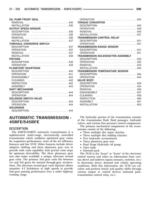
  • 5. DIAGNOSIS AND TESTING - HYDRAULIC PRESSURE TEST An accurate tachometer and pressure test gauges are required. Test Gauge C-3293-SP has a 300 psi range and is used at all locations where pressures exceed 100 psi. Pressure Test Port Locations Only two pressure ports are supplied on the trans- mission case. The torque converter clutch apply and release ports are located on the right side of the transmission case (Fig. 2). To determine the line pressure, there are two avail- able methods. The DRB௡ scan tool can be used to read line pressure from the line pressure sensor. The second method is to install Line Pressure Adapter 8259 (Fig. 4) into the transmission case and then install the pressure gauge and the original sensor into the adapter. This will allow a comparison of the DRB௡ readings and the gauge reading to determine the accuracy of the line pressure sensor. The DRB௡ line pressure reading should match the gauge read- ing within ±10 psi. In order to access any other pressure tap locations, the transmission oil pan must be removed, the pres- sure port plugs removed and Valve Body Pressure Tap Adapter 8258-A (Fig. 5) installed. The extensions supplied with Adapter 8258-A will allow the installa- tion of pressure gauges to the valve body. Refer to (Fig. 3) for correct pressure tap location identifica- tion. Fig. 2 Torque Converter Pressure Locations 1 - TCC RELEASE 2 - TO COOLER 3 - TCC APPLY 4 - FROM COOLER 5 - LINE PRESSURE SENSOR Fig. 3 Pressure Tap Locations Fig. 4 Line Pressure Adapter 8259 1 - LINE PRESSURE SENSOR PORT 2 - LINE PRESSURE SENSOR 3 - TOOL 8259 4 - PRESSURE TAP 21 - 354 AUTOMATIC TRANSMISSION - 45RFE/545RFE DR AUTOMATIC TRANSMISSION - 45RFE/545RFE (Continued)
  • 6. TEST PROCEDURE All pressure readings should be taken with the transmission fluid level full, transmission oil at the normal operating temperature, and the engine at 1500 rpm. Check the transmission for proper opera- tion in each gear position that is in question or if a specific element is in question, check the pressure readings in at least two gear positions that employ that element. Refer to the Hydraulic Schematics at the rear of this section to determine the correct pres- sures for each element in a given gear position. NOTE: The 45RFE/545RFE utilizes closed loop con- trol of pump line pressure. The pressure readings may therefore vary greatly but should always follow line pressure. Some common pressures that can be measured to evaluate pump and clutch performance are the upshift/downshift pressures, garage shift pressures, and TCC pressure. The upshift/downshift pressure for all shifts are shown in UPSHIFT PRESSURES and DOWNSHIFT PRESSURES. In-gear maximum pressure for each gear position is shown in IN-GEAR PRESSURES. The garage shift pressure when per- forming a N-R shift is 220 psi for 3.7L/4.7L equipped vehicles and 250 psi for 5.7L equipped vehicles. The garage shift pressure for the R-N shift is 120 psi. The garage shift pressure for the N-1 shift is 135 psi for 3.7L/4.7L equipped vehicles and 165 psi for 5.7L equipped vehicles. Torque converter lock-up pressure is 120 psi for 3.7L/4.7L equipped vehicles and 125 psi for 5.7L equipped vehicles. UPSHIFT PRESSURES ENGINE 1-2 2-3 2prime-3 3-4 2prime-4 2-5 3-5 4-5 5.7L 150 125 125 135 135 135 135 135 3.7L/4.7L 120 120 120 120 120 120 120 130 DOWNSHIFT PRESSURES ENGINE 5-4 5-3 5-2 4-3 4- 2prime 3-2 3- 2prime 2prime-1 2-1 3-1 5.7L 135 135 135 135 135 135 135 135 135 135 3.7L/ 4.7L 120 120 120 120 120 120 120 120 120 120 IN-GEAR PRESSURES ENGINE 1 2 2prime 3 4 5 NEUTRAL REVERSE 5.7L 160 135 135 135 135 135 120 250 3.7L/4.7L 135 120 120 120 120 120 120 220 Fig. 5 Valve Body Pressure Tap Adapter 8258-A 1 - RFE TRANSMISSION 2 - TOOL 8258-A DR AUTOMATIC TRANSMISSION - 45RFE/545RFE 21 - 355 AUTOMATIC TRANSMISSION - 45RFE/545RFE (Continued)
  • 7. DIAGNOSIS AND TESTING - AIR CHECKING TRANSMISSION CLUTCH OPERATION Air-pressure testing can be used to check transmis- sion clutch operation. The test can be conducted with the transmission either in the vehicle or on the work bench, as a final check. Air-pressure testing requires that the oil pan and valve body be removed from the transmission. The clutch apply passages are shown in the Air Pressure Test Passages graphic (Fig. 6). NOTE: The air supply which is used must be free of moisture and dirt. Use a pressure of 30 psi to test clutch operation. Apply air pressure at each port. If the clutch is functioning, a soft thump will be heard as the clutch is applied. The clutch application can also be felt by touching the appropriate element while applying air pressure. As the air pressure is released, the clutch should also release. DIAGNOSIS AND TESTING - CONVERTER HOUSING FLUID LEAK When diagnosing converter housing fluid leaks, two items must be established before repair. (1) Verify that a leak condition actually exists. (2) Determined the true source of the leak. Some suspected converter housing fluid leaks may not be leaks at all. They may only be the result of residual fluid in the converter housing, or excess fluid spilled during factory fill or fill after repair. Converter housing leaks have several potential sources. Through careful observation, a leak source can be identified before removing the transmission for repair. Torque converter seal leaks tend to move along the drive hub and onto the rear of the con- verter. Pump cover seal tend to run down the cover and the inside surface of the bellhousing. Some leaks, or suspected leaks, may be particu- larly difficult to locate. If necessary, a Mopar௡ approved dye may be used to locate a leak. TORQUE CONVERTER LEAK POINTS Possible sources of converter leaks are: (1) Leaks at the weld joint around the outside diameter weld (Fig. 7). (2) Leaks at the converter hub weld (Fig. 7). STANDARD PROCEDURE - ALUMINUM THREAD REPAIR Damaged or worn threads in the aluminum trans- mission case and valve body can be repaired by the use of Heli-Coils™, or equivalent. This repair con- sists of drilling out the worn-out damaged threads. Then tap the hole with a special Heli-Coil™ tap, or equivalent, and installing a Heli-Coil™ insert, or equivalent, into the hole. This brings the hole back to its original thread size. Heli-Coil™, or equivalent, tools and inserts are readily available from most automotive parts suppli- ers. Fig. 6 Air Pressure Test Passages 1 - LOW REVERSE CLUTCH 2 - 4TH CLUTCH 3 - 2ND CLUTCH 4 - OVERDRIVE CLUTCH 5 - UNDERDRIVE CLUTCH 6 - REVERSE CLUTCH Fig. 7 Torque Converter Assembly 1 - TURBINE ASSEMBLY 2 - STATOR 3 - CONVERTER HUB 4 - O-RING 5 - IMPELLER ASSEMBLY 6 - CONVERTER CLUTCH PISTON 7 - TURBINE HUB 21 - 356 AUTOMATIC TRANSMISSION - 45RFE/545RFE DR AUTOMATIC TRANSMISSION - 45RFE/545RFE (Continued)
  • 8. REMOVAL (1) Disconnect the negative battery cable. (2) Raise and support the vehicle (3) Remove any necessary skid plates. (Refer to 13 - FRAMES & BUMPERS/FRAME/TRANSFER CASE SKID PLATE - REMOVAL) (4) Mark propeller shaft and axle companion flanges for assembly alignment. (5) Remove the rear propeller shaft (6) Remove the front propeller shaft, if necessary. (7) Remove the engine to transmission collar (Fig. 8). (8) Remove the exhaust support bracket from the rear of the transmission. (9) Disconnect and lower or remove any necessary exhaust components. (10) Remove the starter motor. (11) Rotate crankshaft in clockwise direction until converter bolts are accessible. Then remove bolts one at a time. Rotate crankshaft with socket wrench on dampener bolt. (12) Disengage the output speed sensor connector from the output speed sensor (Fig. 9). (13) Disengage the input speed sensor connector from the input speed sensor (Fig. 10). (14) Disengage the transmission solenoid/TRS assembly connector from the transmission solenoid/ TRS assembly (Fig. 11). (15) Disengage the line pressure sensor connector from the line pressure sensor (Fig. 12). (16) Disconnect gearshift cable from transmission manual valve lever (Fig. 13). (17) Disconnect the transmission vent hose from the transmission. (18) Support rear of engine with safety stand or jack. (19) Raise transmission slightly with service jack to relieve load on crossmember and supports. (20) Remove bolts securing rear support and cush- ion to transmission and crossmember. (21) Remove transfer case, if necessary. (22) Disconnect transmission fluid cooler lines at transmission fittings and clips. (23) Remove all remaining converter housing bolts. (24) Carefully work transmission and torque con- verter assembly rearward off engine block dowels. Fig. 8 Transmission Collar 1 - ENGINE 2 - STRUCTURAL DUST COVER 3 - TRANSMISSION Fig. 9 Disconnect Output Speed Sensor 1 - TRANSMISSION 2 - OUTPUT SPEED SENSOR Fig. 10 Disconnect Input Speed Sensor 1 - TRANSMISSION 2 - INPUT SPEED SENSOR DR AUTOMATIC TRANSMISSION - 45RFE/545RFE 21 - 357 AUTOMATIC TRANSMISSION - 45RFE/545RFE (Continued)
  • 9. (25) Hold torque converter in place during trans- mission removal. (26) Lower transmission and remove (Fig. 14) assembly from under the vehicle. (27) To remove torque converter, carefully slide torque converter out of the transmission. Fig. 11 Disconnect Transmission Solenoid/TRS Assembly 1 - TRANSMISSION 2 - TRANSMISSION SOLENOID/TRS ASSEMBLY Fig. 12 Disconnect Line Pressure Sensor 1 - TRANSMISSION 2 - LINE PRESSURE SENSOR Fig. 13 Gearshift Cable at Transmission - RFE 1 - GEARSHIFT CABLE 2 - RFE TRANSMISSION 3 - MANUAL LEVER Fig. 14 Remove Transmission 1 - ENGINE 2 - TRANSMISSION 21 - 358 AUTOMATIC TRANSMISSION - 45RFE/545RFE DR AUTOMATIC TRANSMISSION - 45RFE/545RFE (Continued)
  • 10. DISASSEMBLY (1) Drain fluid from transmission. (2) Clean exterior of transmission with suitable solvent or pressure washer. (3) Remove the torque converter from the trans- mission. (4) Remove the manual shift lever (1) (Fig. 15) from the transmission. (5) Remove the input (3), output (1), and line pres- sure sensors (2) from the transmission case. (Fig. 16) (6) Inspect the ends of the sensors for debris, which may indicate the nature of the transmission failure. (7) Install Support Stand 8257 (1) onto the trans- mission case. (Fig. 17) (8) Using Adapter 8266-1 from End-Play Tool Set 8266 (1) and Dial Indicator C-3339 (2), measure and record the input shaft end-play. (Fig. 18) Fig. 15 Remove the Manual Shaft Lever 1 - MANUAL SHAFT LEVER Fig. 16 Remove Input, Output, and Line Pressure Sensors 1 - OUTPUT SPEED SENSOR 2 - LINE PRESSURE SENSOR 3 - INPUT SPEED SENSOR Fig. 17 Install Support Stand - Tool 8257 1 - TOOL 8257 Fig. 18 Measure Input Shaft End Play 1 - TOOL 8266 2 - TOOL C-3339 DR AUTOMATIC TRANSMISSION - 45RFE/545RFE 21 - 359 AUTOMATIC TRANSMISSION - 45RFE/545RFE (Continued)
  • 11. NOTE: When measuring the input shaft end-play, two ؆stops؆ will be felt. When the input shaft is pushed inward and the dial indicator zeroed, the first ؆stop؆ felt when the input shaft is pulled out- ward is the movement of the input shaft in the input clutch housing hub. This value should not be included in the end-play measured value and there- fore must be recorded and subtracted from the dial indicator reading. (9) Remove the bolts holding the transmission extension/adapter housing to the transmission case. (10) Remove the extension/adapter housing from the transmission case. (11) Using Alignment Plate 8261 (1), Adapter 8266-17 from End-Play Tool Set 8266 (2) and Dial Indicator C-3339 (3), measure and record the output shaft end-play. (Fig. 19) (12) Remove the bolts holding the transmission oil pan to the transmission case. (13) Remove the transmission oil pan from the transmission case. (14) Remove the primary oil filter (1) and the oil cooler return filter (2). (Fig. 20) (15) Remove the cooler return filter bypass valve (3). (16) Remove the bolts (1) holding the valve body to the transmission case. (Fig. 21) Fig. 19 Measure Output Shaft End Play 1 - TOOL 8261 2 - TOOL 8266 3 - TOOL C-3339 Fig. 20 Remove Primary Oil and Cooler Filters 1 - PRIMARY OIL FILTER 2 - COOLER RETURN FILTER 3 - COOLER RETURN FILTER BYPASS VALVE 4 - VALVE BODY Fig. 21 Remove Valve Body Assembly 1 - VALVE BODY TO CASE BOLT (6) 21 - 360 AUTOMATIC TRANSMISSION - 45RFE/545RFE DR AUTOMATIC TRANSMISSION - 45RFE/545RFE (Continued)
  • 12. (17) Remove the valve body from the transmission case. (18) Remove the outer snap-ring (3) securing the transmission front cover (2) into the transmission case. (Fig. 22) (19) Remove the inner snap-ring (1) securing the transmission front cover to the oil pump. (Fig. 22) (20) Reaching through a case opening in the valve body area with a long blunted tool, remove the trans- mission front cover from the transmission case. (21) Remove the bolts (1) holding the oil pump into the transmission case. (Fig. 23) (22) Remove the oil pump (2). Hold inward on the input shaft to prevent pulling the input clutch assembly with the oil pump. (Fig. 23) CAUTION: If the input shaft is not held during oil pump removal, the input clutch assembly will attempt to move forward with the oil pump and the numbers 2, 3, or 4 bearings inside the input clutch assembly may become dislodged. (23) Remove the number 1 thrust bearing (4) from the input clutch assembly. (Fig. 24) (24) Remove the input clutch assembly (3) from the transmission case. (Fig. 24) (25) Remove the number 5 thrust bearing (1) and selective thrust plate (2) from the input clutch assembly (3) (Fig. 24), or the 4C clutch retainer/bulk- head. Fig. 22 Remove Transmission Front Cover 1 - INNER SNAP-RING 2 - TRANSMISSION FRONT COVER 3 - OUTER SNAP-RING Fig. 23 Remove Oil Pump 1 - OIL PUMP TO CASE BOLT (6) 2 - OIL PUMP Fig. 24 Remove Input Clutch Assembly 1 - THRUST BEARING NUMBER 5 2 - THRUST PLATE (SELECT) 3 - INPUT CLUTCH ASSEMBLY 4 - THRUST BEARING NUMBER 1 DR AUTOMATIC TRANSMISSION - 45RFE/545RFE 21 - 361 AUTOMATIC TRANSMISSION - 45RFE/545RFE (Continued)
  • 13. (26) Remove the 4C clutch retainer/bulkhead tapered snap-ring (1) from the transmission case. (Fig. 25) (27) Remove the 4C clutch retainer/bulkhead (2) from the transmission case. (Fig. 25) (28) Remove the front 2C clutch pack snap-ring (1) from the transmission case. (Fig. 26) (29) Remove the 2C clutch pack (2, 3, 4) from the transmission case. (Fig. 26) (30) Remove the rear selective plate (6) and num- ber 6 thrust bearing (7) from the reaction annulus (8). (Fig. 27) (31) Remove the reaction annulus (8) from the reaction planetary carrier (3). (Fig. 27) (32) Remove the number 7 thrust bearing (5). (Fig. 27) (33) Remove the reaction sun gear (4). (Fig. 27) (34) Remove the number 8 thrust bearing (1) from the reaction planetary carrier (3). (Fig. 27) (35) Remove the reaction planetary carrier (3) (Fig. 27). Note that this planetary gear set has three pinion gears. (36) Remove the number 9 thrust bearing (2) from the reverse planetary gear set. (Fig. 27) Fig. 25 Remove 4C Clutch Retainer/Bulkhead 1 - SNAP-RING 2 - 4C CLUTCH RETAINER/BULKHEAD Fig. 26 Remove 2C Clutch Pack 1 - SNAP-RING 2 - PLATE 3 - DISC 4 - REACTION PLATE 21 - 362 AUTOMATIC TRANSMISSION - 45RFE/545RFE DR AUTOMATIC TRANSMISSION - 45RFE/545RFE (Continued)
  • 14. Fig. 27 Remove Reaction Annulus and Carrier 1 - THRUST BEARING NUMBER 8 5 - THRUST BEARING NUMBER 7 2 - THRUST BEARING NUMBER 9 6 - THRUST PLATE (SELECT) 3 - REACTION PLANETARY CARRIER 7 - THRUST BEARING NUMBER 6 4 - REACTION SUN GEAR 8 - REACTION ANNULUS DR AUTOMATIC TRANSMISSION - 45RFE/545RFE 21 - 363 AUTOMATIC TRANSMISSION - 45RFE/545RFE (Continued)
  • 15. (37) Remove the snap-ring (1) holding the park sprag gear onto the output shaft. (Fig. 28) (38) Remove the park sprag gear (1) from the out- put shaft. (Fig. 29) (39) Remove the input/reverse planetary assembly (1). (Fig. 30) (40) Remove the number 12 thrust bearing (3) from the input/reverse planetary assembly (1). (Fig. 30) (41) Remove the snap-ring (2) holding the low/re- verse clutch retainer (1) into the transmission case. (Fig. 31) (42) Remove the low/reverse clutch retainer (1) from the transmission case. (Fig. 31) Fig. 28 Remove Park Sprag Snap-Ring 1 - SNAP-RING Fig. 29 Remove Park Sprag Gear 1 - PARK SPRAG GEAR Fig. 30 Remove Input/Reverse Planetary Assembly 1 - INPUT/REVERSE PLANETARY ASSEMBLY 2 - BEARING NUMBER 9 3 - BEARING NUMBER 12 Fig. 31 Remove Low/Reverse Clutch Retainer 1 - LOW/REVERSE OVERRUNNING CLUTCH ASSEMBLY 2 - SNAP-RING 21 - 364 AUTOMATIC TRANSMISSION - 45RFE/545RFE DR AUTOMATIC TRANSMISSION - 45RFE/545RFE (Continued)
  • 16. (43) Remove the park rod (7) and e-clip. (Fig. 32) (44) Remove the park rod guide snap-ring (2). (Fig. 32) (45) Remove the park rod guide (1). (Fig. 32) (46) Remove the park pawl pivot shaft (3), park pawl (5), and spring (4). (Fig. 32) (47) Remove the manual selector shaft (6). (Fig. 32) (48) Remove the manual selector shaft seal. (49) Remove the dipstick tube seal. CLEANING The use of crocus cloth is permissible where neces- sary, providing it is used carefully. When used on shafts, or valves, use extreme care to avoid rounding off sharp edges. Sharp edges are vital as they prevent foreign matter from getting between the valve and valve bore. Do not reuse oil seals, gaskets, seal rings, or O-rings during overhaul. Replace these parts as a matter of course. Also do not reuse snap rings or E-clips that are bent or distorted. Replace these parts as well. Lubricate transmission parts with Mopar௡ ATF +4, Automatic Transmission Fluid, during overhaul and assembly. Use petroleum jelly, Mopar௡ Door Ease, or Ru-Glyde to prelubricate seals, O-rings, and thrust washers. Petroleum jelly can also be used to hold parts in place during reassembly. Clean the case in a solvent tank. Flush the case bores and fluid passages thoroughly with solvent. Dry the case and all fluid passages with compressed air. Be sure all solvent is removed from the case and that all fluid passages are clear. NOTE: Do not use shop towels or rags to dry the case (or any other transmission component) unless they are made from lint-free materials. Lint will stick to case surfaces and transmission components and circulate throughout the transmission after assem- bly. A sufficient quantity of lint can block fluid pas- sages and interfere with valve body operation. INSPECTION Inspect the case for cracks, porous spots, worn bores, or damaged threads. Damaged threads can be repaired with Helicoil௡ thread inserts. However, the case will have to be replaced if it exhibits any type of damage or wear. ASSEMBLY NOTE: Clean and inspect all components. Replace any components which show evidence of excessive wear or scoring. (1) Install the cooler filter bypass valve. Torque the bypass valve to specification. The valve uses a tapered pipe thread and excessive torque can damage the transmission case. Tighten the cooler filter bypass valve to 4.5 N·m (40 in.lbs.). (2) Install a new selector shaft seal (1) using Seal Installer 8253 (2). (Fig. 33) Fig. 32 Manual Shaft/Park Lock Components 1 - GUIDE 2 - SNAP-RING 3 - SHAFT 4 - SPRING 5 - PARK PAWL 6 - MANUAL SHAFT/LEVER 7 - PARK ROD Fig. 33 Install Selector Shaft Seal 1 - SEAL 2 - TOOL 8253 DR AUTOMATIC TRANSMISSION - 45RFE/545RFE 21 - 365 AUTOMATIC TRANSMISSION - 45RFE/545RFE (Continued)
  • 17. (3) Install the manual selector shaft and retaining screw. Tighten the manual selector shaft retaining screw to 28 N·m (250 in.lbs.). (4) Install the manual shift lever (1) (Fig. 34) onto the manual selector shaft. Torque the retaining cross- bolt to 16 N·m (140 in.lbs.). (5) Install the park pawl (5), spring (4), and shaft (3). (Fig. 35) (6) Install the park rod (7) and e-clip. (Fig. 35) (7) Install the park rod guide (1) and snap-ring (2). (Fig. 35) (8) Install a new dipstick tube seal (2) using Seal Installer 8254 (1). (Fig. 36) NOTE: Before final assembly of transmission cen- terline, the 2C/4C clutch components should be installed into position and measured as follows: (9) Install the 2C reaction plate (4) into the trans- mission case. (Fig. 37) Fig. 34 Remove the Manual Shaft Lever 1 - MANUAL SHAFT LEVER Fig. 35 Manual Shaft/Park Lock Components 1 - GUIDE 2 - SNAP-RING 3 - SHAFT 4 - SPRING 5 - PARK PAWL 6 - MANUAL SHAFT/LEVER 7 - PARK ROD Fig. 36 Install Dipstick Tube Seal Using Tool 8254 1 - TOOL 8254 2 - SEAL 21 - 366 AUTOMATIC TRANSMISSION - 45RFE/545RFE DR AUTOMATIC TRANSMISSION - 45RFE/545RFE (Continued)
  • 18. (10) Install the 2C clutch pack (2, 3) into the transmission case. (Fig. 37) (11) Install the flat 2C clutch snap-ring (1) into the transmission case. (Fig. 37) (12) Install the 4C retainer/bulkhead (2) (Fig. 38) into the transmission case. Make sure that the oil feed holes are pointing toward the valve body area. (13) Install the 4C retainer/bulkhead tapered snap-ring (1) into the transmission case. Make sure that the open ends of the snap-ring are located in the case opening toward the valve body area. (14) Using a feeler gauge through the opening in the rear of the transmission case, measure the 2C clutch pack clearance between the 2C reaction plate and the transmission case at four different points. The average of these measurements is the 2C clutch pack clearance. The correct clutch clearance is 0.455- 1.335 mm (0.018-0.053 in.). The reaction plate is not selective. If the clutch pack clearance is not within specification, the reaction plate, all the friction discs, and steels must be replaced. (15) Remove the 4C retainer/bulkhead and all of the 2C clutch components from the transmission case. (16) Install the low/reverse clutch assembly (1) (Fig. 39). Make sure that the oil feed hole points toward the valve body area and that the bleed orifice is aligned with the notch in the rear of the transmis- sion case. (17) Install the snap-ring (2) (Fig. 39) to hold the low/reverse clutch retainer into the transmission case. The snap-ring is tapered and must be installed with the tapered side forward. Once installed, verify that the snap-ring is fully seated in the snap-ring groove. (18) Air check the low/reverse clutch and verify correct overrunning clutch operation. Fig. 37 Install 2C Clutch Pack 1 - SNAP-RING 2 - PLATE 3 - DISC 4 - REACTION PLATE Fig. 38 Install 4C Clutch Retainer/Bulkhead 1 - SNAP-RING 2 - 4C CLUTCH RETAINER/BULKHEAD Fig. 39 Install Low/Reverse Clutch Retainer 1 - LOW/REVERSE OVERRUNNING CLUTCH ASSEMBLY 2 - SNAP-RING DR AUTOMATIC TRANSMISSION - 45RFE/545RFE 21 - 367 AUTOMATIC TRANSMISSION - 45RFE/545RFE (Continued)
  • 19. (19) Install the number 12 thrust bearing (3) over the output shaft and against the rear planetary gear set. The flat side of the bearing goes toward the plan- etary gearset and the raised tabs on the inner race should face the rear of the transmission. (20) Install the reverse/input planetary assembly (1) through the low/reverse clutch assembly. (Fig. 40) (21) Install the park sprag gear (1) onto the output shaft. (Fig. 41) (22) Install the snap-ring (1) to hold the park sprag onto the output shaft. (Fig. 42) (23) Install the 2C reaction plate (4) into the transmission case. (Fig. 43) (24) Install the 2C clutch pack (2, 3, 4) into the transmission case. (Fig. 43) (25) Install the number 8 thrust bearing (1) inside the reaction carrier with the outer race against the reaction planetary carrier (3). (26) Install the reaction planetary gear set and the number 9 thrust bearing (2), with the inner race against the reaction planetary carrier (3), into the transmission case. (Fig. 44) Fig. 40 Install Input/Reverse Planetary Assembly 1 - INPUT/REVERSE PLANETARY ASSEMBLY 2 - BEARING NUMBER 9 3 - BEARING NUMBER 12 Fig. 41 Install Park Sprag Gear 1 - PARK SPRAG GEAR Fig. 42 Install Park Sprag Snap-Ring 1 - SNAP-RING Fig. 43 Install 2C Clutch Pack 1 - SNAP-RING 2 - PLATE 3 - DISC 4 - REACTION PLATE 21 - 368 AUTOMATIC TRANSMISSION - 45RFE/545RFE DR AUTOMATIC TRANSMISSION - 45RFE/545RFE (Continued)
  • 20. (27) Install the flat 2C clutch snap-ring into the transmission case. (Fig. 43) (28) Install the reaction sun gear (4) into the reac- tion planetary gear set. Make sure the small shoul- der is facing the front of the transmission. (Fig. 44) (29) Install the number 7 thrust bearing (5) onto the reaction sun gear (4) with the inner race against the sun gear. (Fig. 44) (30) Install the output shaft selective thrust plate (2) onto the reaction annulus with the oil grooves fac- ing the annulus gear and the lugs (1) and notches aligned as shown. (Fig. 45) (31) Install the number 6 thrust bearing (7) against the output shaft selective thrust plate (6) with the flat side against the thrust plate (Fig. 44) and the raised tabs on the inner race facing the front of the transmission. (32) Install the reaction annulus (8) into the reac- tion planetary gear set. (Fig. 44) (33) Install the 4C retainer/bulkhead (2) into the transmission case. Make sure that the oil feed holes are pointing toward the valve body area. Rotate the reaction annulus during the installation of the 4C retainer/bulkhead to ease installation. (34) Install the 4C retainer/bulkhead tapered snap-ring (1) into the transmission case (Fig. 46) with the taper toward the front of the case. Make sure that the open ends of the snap-ring are located in the case opening toward the valve body area. (35) Air check the 2C and 4C clutch operation. (36) Using Alignment Plate 8261 (1), Adapter 8266-17 from End-Play Tool Set 8266 (2) and Dial Indicator C-3339 (3), measure (Fig. 47) and record the output shaft end-play. The correct output shaft end-play is 0.22-0.55 mm (0.009-0.021 in.). Adjust as necessary. Install the chosen output shaft selective thrust plate and re-measure end-play to verify selec- tion. Fig. 44 Install Reaction Annulus and Carrier 1 - THRUST BEARING NUMBER 8 5 - THRUST BEARING NUMBER 7 2 - THRUST BEARING NUMBER 9 6 - THRUST PLATE (SELECT) 3 - REACTION PLANETARY CARRIER 7 - THRUST BEARING NUMBER 6 4 - REACTION SUN GEAR 8 - REACTION ANNULUS DR AUTOMATIC TRANSMISSION - 45RFE/545RFE 21 - 369 AUTOMATIC TRANSMISSION - 45RFE/545RFE (Continued)
  • 21. (37) Apply a bead of RTV silicone and install the extension/adapter housing onto the transmission case. (38) Install and torque the bolts to hold the exten- sion/adapter housing onto the transmission case. The correct torque is 54 N·m (40 ft.lbs.). (39) Install the number 5 thrust bearing (1) (Fig. 48) and selective thrust plate (2) onto the 4C retain- er/bulkhead. Be sure that the outer race of the bear- ing is against the thrust plate. (40) Install the input clutch assembly (3) (Fig. 48) into the transmission case. Make sure that the input clutch assembly is fully installed by performing a visual inspection through the input speed sensor hole. If the tone wheel teeth on the input clutch assembly are centered in the hole, the assembly is fully installed. (41) Install the number 1 thrust bearing (4) with the outer race up in the pocket of the input clutch assembly. (Fig. 48) Fig. 45 Thrust Plate Alignment 1 - LOCATING LUG (3) 2 - THRUST PLATE Fig. 46 Install 4C Clutch Retainer/Bulkhead 1 - SNAP-RING 2 - 4C CLUTCH RETAINER/BULKHEAD Fig. 47 Measure Output Shaft End Play 1 - TOOL 8261 2 - TOOL 8266 3 - TOOL C-3339 Fig. 48 Install Input Clutch Assembly 1 - THRUST BEARING NUMBER 5 2 - THRUST PLATE (SELECT) 3 - INPUT CLUTCH ASSEMBLY 4 - THRUST BEARING NUMBER 1 21 - 370 AUTOMATIC TRANSMISSION - 45RFE/545RFE DR AUTOMATIC TRANSMISSION - 45RFE/545RFE (Continued)
  • 22. (42) Install the oil pump (2) into the transmission case. (Fig. 49) (43) Install the bolts (1) to hold the oil pump into the transmission case. Tighten the oil pump bolts to 28 N·m (250 in.lbs.). (44) Using Adapter 8266-1 from End-Play Tool Set 8266 (1) and Dial Indicator C-3339 (2), measure (Fig. 50) and record the input shaft end-play. The correct end-play is 0.46-0.89 mm (0.018-0.035 in.). Adjust as necessary. Install the chosen thrust plate on the number 5 thrust bearing and re-measure end-play to verify selection. NOTE: When measuring the input shaft end-play, two ؆stops؆ will be felt. When the input shaft is pushed inward and the dial indicator zeroed, the first ؆stop؆ felt when the input shaft is pulled out- ward is the movement of the input shaft in the input clutch housing hub. This value should not be included in the end-play measured value and there- fore must be recorded and subtracted from the dial indicator reading. (45) Install the transmission front cover (2) into the transmission case. (Fig. 51) (46) Install the outer snap-ring (3) to hold the transmission front cover (2) into the transmission case. (Fig. 51) (47) Partially install the inner transmission front cover snap-ring (1) onto the oil pump. (Fig. 51) (48) Using Installer 8255 (1), install the inner transmission front cover snap-ring (2) the remainder of the way onto the oil pump. (Fig. 52) (49) Install the valve body. Verify that the pin on the manual lever has properly engaged the TRS selector plate. Tighten the valve body to transmission case bolts (1) (Fig. 53) to 12 N·m (105 in.lbs.). CAUTION: The primary oil filter seal MUST be fully installed flush against the oil pump body. DO NOT install the seal onto the filter neck and attempt to install the filter and seal as an assembly. Damage to the transmission will result. Fig. 49 Install Oil Pump 1 - OIL PUMP TO CASE BOLT (6) 2 - OIL PUMP Fig. 50 Measure Input Shaft End Play 1 - TOOL 8266 2 - TOOL C-3339 Fig. 51 Install the Transmission Front Cover 1 - INNER SNAP-RING 2 - TRANSMISSION FRONT COVER 3 - OUTER SNAP-RING DR AUTOMATIC TRANSMISSION - 45RFE/545RFE 21 - 371 AUTOMATIC TRANSMISSION - 45RFE/545RFE (Continued)
  • 23. (50) Install a new primary oil filter seal in the oil pump inlet bore. Seat the seal in the bore with the butt end of a hammer, or other suitable tool. (51) Install the primary oil filter (1) (Fig. 54) and the oil cooler return filter (2). Tighten the screw to hold the primary oil filter to the valve body to 4.5 N·m (40 in.lbs.). Using Oil Filter Wrench 8321, tighten the cooler return oil filter to the transmission case to 14 N·m (125 in.lbs.). (52) Apply RTV silicone to the oil pan and install the transmission oil pan. Tighten the bolts to 12 N·m (105 in.lbs.). (53) Install the input (3), output (1), and line pres- sure sensors (2) (Fig. 55). Tighten the bolts to 12 N·m (105 in.lbs.). INSTALLATION (1) Check torque converter hub and hub drive flats for sharp edges burrs, scratches, or nicks. Polish the hub and flats with 320/400 grit paper and crocus cloth if necessary. Verify that the converter hub o-ring is properly installed and is free of any debris. The hub must be smooth to avoid damaging pump seal at installation. Fig. 52 Seat Snap-Ring Using Tool 8255 1 - TOOL 8255 2 - SNAP-RING Fig. 53 Install Valve Body Assembly 1 - VALVE BODY TO CASE BOLT (6) Fig. 54 Install Primary Oil and Cooler Filters 1 - PRIMARY OIL FILTER 2 - COOLER RETURN FILTER 3 - COOLER RETURN FILTER BYPASS VALVE 4 - VALVE BODY Fig. 55 Install Input, Output, and Line Pressure Sensors 1 - OUTPUT SPEED SENSOR 2 - LINE PRESSURE SENSOR 3 - INPUT SPEED SENSOR 21 - 372 AUTOMATIC TRANSMISSION - 45RFE/545RFE DR AUTOMATIC TRANSMISSION - 45RFE/545RFE (Continued)
  • 24. (2) If a replacement transmission is being installed, transfer any components necessary, such as the manual shift lever and shift cable bracket, from the original transmission onto the replacement trans- mission. (3) Lubricate oil pump seal lip with transmission fluid. (4) Align converter and oil pump. (5) Carefully insert converter in oil pump. Then rotate converter back and forth until fully seated in pump gears. (6) Check converter seating with steel scale and straightedge (Fig. 56). Surface of converter lugs should be at least 13mm (1/2 in.) to rear of straight- edge when converter is fully seated. (7) Temporarily secure converter with C-clamp. (8) Position transmission on jack and secure it with chains. (9) Check condition of converter driveplate. Replace the plate if cracked, distorted or damaged. Also be sure transmission dowel pins are seated in engine block and protrude far enough to hold transmission in alignment. (10) Apply a light coating of Mopar௡ High Temp Grease to the torque converter hub pocket in the rear pocket of the engine’s crankshaft. (11) Raise transmission (Fig. 57) and align the torque converter with the drive plate and transmis- sion converter housing with the engine block. (12) Move transmission forward. Then raise, lower or tilt transmission to align the converter housing with engine block dowels. (13) Carefully work transmission forward and over engine block dowels until converter hub is seated in crankshaft. Verify that no wires, or the transmission vent hose, have become trapped between the engine block and the transmission. (14) Install two bolts to attach the transmission to the engine. (15) Install remaining torque converter housing to engine bolts. Tighten to 68 N·m (50 ft.lbs.). (16) Install transfer case, if equipped. Tighten transfer case nuts to 35 N·m (26 ft.lbs.). (17) Install rear support to transmission. Tighten bolts to 47 N·m (35 ft.lbs.). (18) Lower transmission onto crossmember and install bolts attaching transmission mount to cross- member. Tighten clevis bracket to crossmember bolts to 47 N·m (35 ft.lbs.). Tighten the clevis bracket to rear support bolt to 68 N·m (50 ft.lbs.). (19) Remove engine support fixture. (20) Connect gearshift cable to transmission. (21) Connect wires to solenoid and pressure switch assembly (Fig. 58) connector, input (Fig. 59) and out- put (Fig. 60) speed sensors, and line pressure sensor (Fig. 61). Be sure transmission harnesses are prop- erly routed. CAUTION: It is essential that correct length bolts be used to attach the converter to the driveplate. Bolts that are too long will damage the clutch surface inside the converter. (22) Install torque converter-to-driveplate bolts. Tighten bolts to 31 N·m (270 in. lbs.). (23) Install starter motor and cooler line bracket. (24) Connect cooler lines to transmission. (25) Install transmission fill tube. (26) Install exhaust components, if necessary. Fig. 56 Checking Torque Converter Seating - Typical 1 - SCALE 2 - STRAIGHTEDGE Fig. 57 Install Transmission 1 - ENGINE 2 - TRANSMISSION DR AUTOMATIC TRANSMISSION - 45RFE/545RFE 21 - 373 AUTOMATIC TRANSMISSION - 45RFE/545RFE (Continued)
  • 25. (27) Install the structural dust cover (Fig. 62) (Refer to 9 - ENGINE/ENGINE BLOCK/STRUC- TURAL COVER - INSTALLATION) onto the trans- mission and the engine. (28) Align and connect propeller shaft(s). (29) Adjust gearshift cable if necessary. (30) Install any skid plates removed previously. (Refer to 13 - FRAMES & BUMPERS/FRAME/ TRANSFER CASE SKID PLATE - INSTALLATION) (31) Lower vehicle. (32) Fill transmission with Mopar௡ ATF +4, Auto- matic Transmission Fluid. Fig. 62 Transmission Collar 1 - ENGINE 2 - STRUCTURAL DUST COVER 3 - TRANSMISSION Fig. 58 Connect Transmission Solenoid 1 - TRANSMISSION 2 - TRANSMISSION SOLENOID/TRS ASSEMBLY Fig. 59 Connect Input Speed Sensor 1 - TRANSMISSION 2 - INPUT SPEED SENSOR Fig. 60 Connect Output Speed Sensor 1 - TRANSMISSION 2 - OUTPUT SPEED SENSOR Fig. 61 Connect Line Pressure Sensor 1 - TRANSMISSION 2 - LINE PRESSURE SENSOR 21 - 374 AUTOMATIC TRANSMISSION - 45RFE/545RFE DR AUTOMATIC TRANSMISSION - 45RFE/545RFE (Continued)
  • 26. SCHEMATICS AND DIAGRAMS HYDRAULIC SCHEMATICS HYDRAULICFLOWINPARK/NEUTRAL DR AUTOMATIC TRANSMISSION - 45RFE/545RFE 21 - 375 AUTOMATIC TRANSMISSION - 45RFE/545RFE (Continued)
  • 27. HYDRAULICFLOWINNEUTRALOVER8MPH 21 - 376 AUTOMATIC TRANSMISSION - 45RFE/545RFE DR AUTOMATIC TRANSMISSION - 45RFE/545RFE (Continued)
  • 28. HYDRAULICFLOWINREVERSE DR AUTOMATIC TRANSMISSION - 45RFE/545RFE 21 - 377 AUTOMATIC TRANSMISSION - 45RFE/545RFE (Continued)
  • 29. HYDRAULICFLOWINREVERSEBLOCK 21 - 378 AUTOMATIC TRANSMISSION - 45RFE/545RFE DR AUTOMATIC TRANSMISSION - 45RFE/545RFE (Continued)
  • 30. HYDRAULICFLOWINFIRSTGEAR(FROMNOROD) DR AUTOMATIC TRANSMISSION - 45RFE/545RFE 21 - 379 AUTOMATIC TRANSMISSION - 45RFE/545RFE (Continued)
  • 31. HYDRAULICFLOWINFIRSTGEAR(AFTERLAUNCHFROMREST) 21 - 380 AUTOMATIC TRANSMISSION - 45RFE/545RFE DR AUTOMATIC TRANSMISSION - 45RFE/545RFE (Continued)
  • 32. HYDRAULICFLOWINFIRSTGEAR(FROMK/D) DR AUTOMATIC TRANSMISSION - 45RFE/545RFE 21 - 381 AUTOMATIC TRANSMISSION - 45RFE/545RFE (Continued)
  • 33. HYDRAULICFLOWINSECONDGEAR 21 - 382 AUTOMATIC TRANSMISSION - 45RFE/545RFE DR AUTOMATIC TRANSMISSION - 45RFE/545RFE (Continued)
  • 34. HYDRAULICFLOWINSECONDGEAREMCC DR AUTOMATIC TRANSMISSION - 45RFE/545RFE 21 - 383 AUTOMATIC TRANSMISSION - 45RFE/545RFE (Continued)
  • 35. HYDRAULICFLOWINSECONDPRIMEGEAR 21 - 384 AUTOMATIC TRANSMISSION - 45RFE/545RFE DR AUTOMATIC TRANSMISSION - 45RFE/545RFE (Continued)
  • 36. HYDRAULICFLOWINSECONDPRIMEGEAREMCC DR AUTOMATIC TRANSMISSION - 45RFE/545RFE 21 - 385 AUTOMATIC TRANSMISSION - 45RFE/545RFE (Continued)
  • 37. HYDRAULICFLOWINDIRECTGEAR 21 - 386 AUTOMATIC TRANSMISSION - 45RFE/545RFE DR AUTOMATIC TRANSMISSION - 45RFE/545RFE (Continued)
  • 38. HYDRAULICFLOWINDIRECTGEAR(FAILSAFE) DR AUTOMATIC TRANSMISSION - 45RFE/545RFE 21 - 387 AUTOMATIC TRANSMISSION - 45RFE/545RFE (Continued)
  • 39. HYDRAULICFLOWINDIRECTGEAREMCC 21 - 388 AUTOMATIC TRANSMISSION - 45RFE/545RFE DR AUTOMATIC TRANSMISSION - 45RFE/545RFE (Continued)
  • 40. HYDRAULICFLOWINFOURTH DR AUTOMATIC TRANSMISSION - 45RFE/545RFE 21 - 389 AUTOMATIC TRANSMISSION - 45RFE/545RFE (Continued)
  • 41. HYDRAULICFLOWINFOURTHEMCC 21 - 390 AUTOMATIC TRANSMISSION - 45RFE/545RFE DR AUTOMATIC TRANSMISSION - 45RFE/545RFE (Continued)
  • 42. HYDRAULICFLOWINFIFTH DR AUTOMATIC TRANSMISSION - 45RFE/545RFE 21 - 391 AUTOMATIC TRANSMISSION - 45RFE/545RFE (Continued)
  • 43. HYDRAULICFLOWINFIFTHEMCC 21 - 392 AUTOMATIC TRANSMISSION - 45RFE/545RFE DR AUTOMATIC TRANSMISSION - 45RFE/545RFE (Continued)
  • 44. HYDRAULICFLOWINMANUALLOWORAUTOSTICK1ST DR AUTOMATIC TRANSMISSION - 45RFE/545RFE 21 - 393 AUTOMATIC TRANSMISSION - 45RFE/545RFE (Continued)
  • 45. HYDRAULICFLOWINMANUALSECOND 21 - 394 AUTOMATIC TRANSMISSION - 45RFE/545RFE DR AUTOMATIC TRANSMISSION - 45RFE/545RFE (Continued)
  • 46. HYDRAULICFLOWINMANUALSECOND(FAILSAFE) DR AUTOMATIC TRANSMISSION - 45RFE/545RFE 21 - 395 AUTOMATIC TRANSMISSION - 45RFE/545RFE (Continued)
  • 47. SPECIFICATIONS TRANSMISSION GENERAL Component Metric Inch Output Shaft End Play 0.22-0.55 mm 0.009-0.021 in. Input Shaft End Play 0.46-0.89 mm 0.018-0.035 in. 2C Clutch Pack Clearance 0.455-1.335 mm 0.018-0.053 in. 4C Clutch Pack Clearance 0.770-1.390 mm 0.030-0.055 in. L/R Clutch Pack Clearance 1.00-1.74 mm 0.039-0.069 in. OD Clutch Pack Clearance 1.103-1.856 mm 0.043-0.073 in. Component Metric Inch UD Clutch Pack Clearance 0.84-1.54 mm 0.033-0.061 in. Reverse Clutch Pack Clearance 0.81-1.24 mm 0.032-0.049 in. Recommended fluid Moparா ATF +4 GEAR RATIOS 1ST 3.00:1 2ND 1.67:1 2ND Prime 1.50:1 3RD 1.0:1 4TH 0.75:1 5TH 0.67:1 REVERSE 3.00:1 TORQUE SPECIFICATIONS DESCRIPTION N·m Ft. Lbs. In. Lbs. Fitting, cooler line at trans 17.5 - 155 Bolt, torque convertor 31 23 - Bolt/nut, crossmember 68 50 - Bolt, driveplate to crankshaft 75 55 - Bolt, oil pan 11.8 - 105 Screw, primary fluid filter 4.5 - 40 Bolt, oil pump 28.2 - 250 Bolt, oil pump body to cover 4.5 - 40 Screw, plate to oil pump body 4.5 - 40 Bolt, valve body to case 11.8 - 105 Plug, pressure test port 5.1 - 45 Bolt, reaction shaft support 11.8 - 105 Screw, valve body to transfer plate 5.6 - 50 Screw, solenoid module to transfer plate 5.7 - 50 Screw, accumulator cover 7 - 60 Screw, detent spring 4.5 - 40 Bolt, input speed sensor 11.8 - 105 Bolt, output speed sensor 11.8 - 105 Bolt, line pressure sensor 11.8 - 105 Bolt, extension housing 54 40 - Valve, cooler return filter bypass 4.5 - 40 Screw, manual valve cam retaining 4.5 - 40 Bolt, manual lever 28.2 - 250 21 - 396 AUTOMATIC TRANSMISSION - 45RFE/545RFE DR AUTOMATIC TRANSMISSION - 45RFE/545RFE (Continued)
  • 48. SPECIAL TOOLS RFE TRANSMISSION Gauge, Oil Pressure - C-3292 Gauge, Oil Pressure - C-3293SP Dial Indicator - C-3339 Installer, Seal - C-3860-A Compressor, Spring - 8249 Compressor, Spring - 8250 Compressor, Spring - 8251 Installer, Piston - 8252 DR AUTOMATIC TRANSMISSION - 45RFE/545RFE 21 - 397 AUTOMATIC TRANSMISSION - 45RFE/545RFE (Continued)
  • 49. Installer, Seal - 8253 Installer, Seal - 8254 Installer, Snap-ring - 8255 Stand, Support - 8257 Adapter, Pressure Tap - 8258-A Adapter, Line Pressure - 8259 Fixture, Input Clutch Pressure - 8260 Plate, Alignment - 8261 21 - 398 AUTOMATIC TRANSMISSION - 45RFE/545RFE DR AUTOMATIC TRANSMISSION - 45RFE/545RFE (Continued)
  • 50. End Play Set - 8266 Compressor, Spring - 8285 Installer, Bearing - 8320 Wrench, Filter - 8321 Installer, Piston - 8504 DR AUTOMATIC TRANSMISSION - 45RFE/545RFE 21 - 399 AUTOMATIC TRANSMISSION - 45RFE/545RFE (Continued)
  • 51. RETAINER/BULKHEAD-4C DISASSEMBLY (1) Remove the 2C piston Belleville spring snap- ring (6) from the 4C retainer /bulkhead (13). (Fig. 63) (2) Remove the 2C piston Belleville spring (5) from the retainer/bulkhead (13). (Fig. 63) (3) Remove the 2C piston (2) from the retainer/ bulkhead (13). Use 20 psi of air pressure to remove the piston if necessary. (4) Remove the 4C clutch snap-ring (7) from the retainer/bulkhead (13). (Fig. 63) (5) Remove the 4C clutch pack (3, 4, 8) from the retainer/bulkhead (13). (Fig. 63) (6) Using Spring Compressor 8250 (2) (Fig. 64) and a suitable shop press (1), compress the 4C piston return spring (10) and remove the snap-ring (9). (Fig. 63) (7) Remove the 4C piston return spring (10) (Fig. 63) and piston (12) from the retainer/bulkhead (13). Use 20 psi of air pressure to remove the piston if nec- essary. Fig. 63 4C Retainer/Bulkhead Components 1 - SEAL 8 - REACTION PLATE 2 - 2C PISTON 9 - SNAP-RING 3 - PLATE 10 - RETURN SPRING 4 - DISC 11 - SEAL 5 - 2C BELLEVILLE SPRING 12 - 4C PISTON 6 - SNAP-RING 13 - 4C RETAINER/BULKHEAD 7 - SNAP-RING (SELECT) 21 - 400 AUTOMATIC TRANSMISSION - 45RFE/545RFE DR
  • 52. ASSEMBLY NOTE: Clean and inspect all components. Replace any components which show evidence of excessive wear or scoring. (1) Install new seals (1, 11) on the 2C and 4C pis- tons. (Fig. 65) (2) Lubricate all seals with Mopar௡ ATF +4 prior to installation. (3) Install the 4C piston (12) into the 4C retainer/ bulkhead (13). (Fig. 65) (4) Position the 4C piston return spring (10) onto the 4C piston (12). (5) Using Spring Compressor 8250 (2) and a suit- able shop press (1), compress the 4C piston return spring and install the snap-ring. (Fig. 66) (6) Assemble and install the 4C clutch pack (3, 4) into the retainer/bulkhead (13) (Fig. 65) with the steel separator plate against the piston. (7) Install the 4C reaction plate (8) (Fig. 65) and snap-ring (7) into the retainer/bulkhead (13). The 4C reaction plate is non-directional. (8) Measure the 4C clutch clearance. The correct clutch clearance is 0.77-1.39 mm (0.030-0.055 in.). The snap-ring (7) is selectable. Install the chosen snap-ring and re-measure to verify the selection. (9) Install the 2C piston (2) into the retainer/bulk- head (13). (Fig. 65) (10) Position the 2C Belleville spring (5) onto the 2C piston (2). (11) Position the 2C Belleville spring snap-ring (6) onto the 2C Belleville spring (5). (Fig. 65) Fig. 64 Compress 4C Piston Return Spring Using Tool 8250 1 - PRESS 2 - TOOL 8250 DR AUTOMATIC TRANSMISSION - 45RFE/545RFE 21 - 401 RETAINER/BULKHEAD-4C (Continued)
  • 53. Fig. 65 4C Retainer/Bulkhead Components 1 - SEAL 8 - REACTION PLATE 2 - 2C PISTON 9 - SNAP-RING 3 - PLATE 10 - RETURN SPRING 4 - DISC 11 - SEAL 5 - 2C BELLEVILLE SPRING 12 - 4C PISTON 6 - SNAP-RING 13 - 4C RETAINER/BULKHEAD 7 - SNAP-RING (SELECT) 21 - 402 AUTOMATIC TRANSMISSION - 45RFE/545RFE DR RETAINER/BULKHEAD-4C (Continued)
  • 54. (12) Using Spring Compressor 8249 (2) (Fig. 67) and a suitable shop press (1), compress the Belleville spring (5) until the snap-ring (6) is engaged with the snap-ring groove in the retainer/bulkhead. ADAPTER HOUSING SEAL REMOVAL (1) Remove the transfer case from the transmis- sion. (2) Using a screw mounted on a slide hammer, remove the adapter housing seal. INSTALLATION (1) Clean the adapter seal bore in the adapter housing of any residue or particles remaining from the original seal. (2) Install new oil seal in the adapter housing using Seal Installer C-3860-A (1) (Fig. 68). A properly installed seal is flush to the face of the seal bore. (3) Install the transfer case onto the transmission. Fig. 66 Compress 4C Piston Return Spring Using Tool 8250 1 - PRESS 2 - TOOL 8250 Fig. 67 Compress 2C Belleville Spring Using Tool 8249 1 - PRESS 2 - TOOL 8249 Fig. 68 Adapter Housing Seal Installation 1 - TOOL C-3860-A DR AUTOMATIC TRANSMISSION - 45RFE/545RFE 21 - 403 RETAINER/BULKHEAD-4C (Continued)
  • 55. BRAKE TRANSMISSION SHIFT INTERLOCK SYSTEM DESCRIPTION The Brake Transmission Shifter Interlock (BTSI) (Fig. 69), is a solenoid operated system. It consists of a solenoid permanently mounted on the gearshift cable. OPERATION The system locks the shifter into the PARK posi- tion. The interlock system is engaged whenever the ignition switch is in the LOCK or ACCESSORY posi- tion. An additional electrically activated feature will prevent shifting out of the PARK position unless the brake pedal is depressed approximately one-half an inch. A magnetic holding device in line with the park lock cable is energized when the ignition is in the RUN position. When the key is in the RUN position and the brake pedal is depressed, the shifter is unlocked and will move into any position. The inter- lock system also prevents the ignition switch from being turned to the LOCK or ACCESSORY position, unless the shifter is fully locked into the PARK posi- tion. DIAGNOSIS AND TESTING - BRAKE TRANSMISSION SHIFT INTERLOCK (1) Verify that the key can only be removed in the PARK position. (2) When the shift lever is in PARK And the shift handle pushbutton is in the “OUT” position, the igni- tion key cylinder should rotate freely from OFF to LOCK. When the shifter is in any other gear or neu- tral position, the ignition key cylinder should not rotate to the LOCK position. (3) Shifting out of PARK should not be possible when the ignition key cylinder is in the OFF posi- tion. (4) Shifting out of PARK should not be possible while applying normal pushbutton force and ignition key cylinder is in the RUN or START positions unless the foot brake pedal is depressed approxi- mately 1/2 inch (12mm). (5) Shifting out of PARK should not be possible when the ignition key cylinder is in the ACCESSORY or LOCK positions. (6) Shifting between any gears, NEUTRAL or into PARK may be done without depressing foot brake pedal with ignition switch in RUN or START posi- tions. ADJUSTMENTS - BRAKE TRANSMISSION SHIFT INTERLOCK Correct cable adjustment is important to proper interlock operation. The gearshift cable must be cor- rectly adjusted in order to shift out of PARK. ADJUSTMENT PROCEDURE (1) Remove the steering column trim as necessary for access to the brake transmission shift interlock. (2) Shift the transmission into the PARK position. (3) Pull upward on both the BTSI lock tab (4) and the gearshift cable lock tab (3). (Fig. 70) (4) Verify that the shift lever is in the PARK posi- tion. Fig. 69 Brake Transmission Interlock Mechanism 1 - STEERING COLUMN 2 - GEARSHIFT CABLE 3 - GEARSHIFT CABLE LOCK TAB 4 - BTSI SOLENOID LOCK TAB 5 - BTSI CONNECTOR Fig. 70 Brake Transmission Interlock Mechanism 1 - STEERING COLUMN 2 - GEARSHIFT CABLE 3 - GEARSHIFT CABLE LOCK TAB 4 - BTSI SOLENOID LOCK TAB 5 - BTSI CONNECTOR 21 - 404 AUTOMATIC TRANSMISSION - 45RFE/545RFE DR
  • 56. (5) Verify positive engagement of the transmission park lock by attempting to rotate the propeller shaft. The shaft will not rotate when the park lock is engaged. (6) Turn ignition switch to LOCK position. Be sure ignition key cylinder is in the LOCK posi- tion. Cable will not adjust correctly in any other position. (7) Ensure that the cable is free to self-adjust by pushing cable rearward and releasing. (8) Push the gearshift cable lock tab (3) down until it snaps in place. (9) Locate the BTSI alignment hole in the bottom of the BTSI mechanism between the BTSI lock tab and the BTSI connector. (10) Move the BTSI assembly up or down on the gearshift cable until an appropriate size drill bit can be inserted into the alignment hole and through the assembly. (11) Push the BTSI lock tab (4) down until it snaps into place and remove the drill bit. (12) Install any steering column trim previously removed. BTSI FUNCTION CHECK (1) Verify removal of ignition key allowed in PARK position only. (2) When the shift lever is in PARK, the ignition key cylinder should rotate freely from off to lock. When the shifter is in any other position, the ignition key should not rotate from off to lock. (3) Shifting out of PARK should be possible when the ignition key cylinder is in the off position. (4) Shifting out of PARK should not be possible while applying normal force, and ignition key cylin- der is in the run or start positions, unless the foot brake pedal is depressed approximately 1/2 inch (12mm). (5) Shifting out of PARK should not be possible when the ignition key cylinder is in the accessory or lock position. (6) Shifting between any gear and NEUTRAL, or PARK, may be done without depressing foot brake with ignition switch in run or start positions. (7) Engine starts must be possible with shifter lever in PARK or NEUTRAL positions only. Engine starts must not be possible in any position other than PARK or NEUTRAL. (8) With shifter lever in the: • PARK position - Apply upward force on the shift arm and remove pressure. Engine starts must be possible. • PARK position - Apply downward force on the shift arm and remove pressure. Engine starts must be possible. • NEUTRAL position - Normal position. Engine starts must be possible. • NEUTRAL position - Engine running and brakes applied, apply upward force on the shift arm. Trans- mission shall not be able to shift from neutral to reverse. FLUID AND FILTER DIAGNOSIS AND TESTING DIAGNOSIS AND TESTING - EFFECTS OF INCORRECT FLUID LEVEL A low fluid level allows the pump to take in air along with the fluid. Air in the fluid will cause fluid pressures to be low and develop slower than normal. If the transmission is overfilled, the gears churn the fluid into foam. This aerates the fluid and causing the same conditions occurring with a low level. In either case, air bubbles cause fluid overheating, oxi- dation, and varnish buildup which interferes with valve and clutch operation. Foaming also causes fluid expansion which can result in fluid overflow from the transmission vent or fill tube. Fluid overflow can eas- ily be mistaken for a leak if inspection is not careful. DIAGNOSIS AND TESTING - CAUSES OF BURNT FLUID Burnt, discolored fluid is a result of overheating which has three primary causes. (1) Internal clutch slippage, usually caused by low line pressure, inadequate clutch apply pressure, or clutch seal failure. (2) A result of restricted fluid flow through the main and/or auxiliary cooler. This condition is usu- ally the result of a faulty or improperly installed drainback valve, a damaged oil cooler, or severe restrictions in the coolers and lines caused by debris or kinked lines. (3) Heavy duty operation with a vehicle not prop- erly equipped for this type of operation. Trailer tow- ing or similar high load operation will overheat the transmission fluid if the vehicle is improperly equipped. Such vehicles should have an auxiliary transmission fluid cooler, a heavy duty cooling sys- tem, and the engine/axle ratio combination needed to handle heavy loads. DIAGNOSIS AND TESTING - FLUID CONTAMINATION Transmission fluid contamination is generally a result of: • adding incorrect fluid DR AUTOMATIC TRANSMISSION - 45RFE/545RFE 21 - 405 BRAKE TRANSMISSION SHIFT INTERLOCK SYSTEM (Continued)
  • 57. • failure to clean dipstick and fill tube when checking level • engine coolant entering the fluid • internal failure that generates debris • overheat that generates sludge (fluid break- down) • failure to replace contaminated converter after repair The use of non-recommended fluids can result in transmission failure. The usual results are erratic shifts, slippage, abnormal wear and eventual failure due to fluid breakdown and sludge formation. Avoid this condition by using recommended fluids only. The dipstick cap and fill tube should be wiped clean before checking fluid level. Dirt, grease and other foreign material on the cap and tube could fall into the tube if not removed beforehand. Take the time to wipe the cap and tube clean before withdraw- ing the dipstick. Engine coolant in the transmission fluid is gener- ally caused by a cooler malfunction. The only remedy is to replace the radiator as the cooler in the radiator is not a serviceable part. If coolant has circulated through the transmission, an overhaul is necessary. The torque converter should also be replaced when- ever a failure generates sludge and debris. This is necessary because normal converter flushing proce- dures will not remove all contaminants. STANDARD PROCEDURE STANDARD PROCEDURE - FLUID LEVEL CHECK Low fluid level can cause a variety of conditions because it allows the pump to take in air along with the fluid. As in any hydraulic system, air bubbles make the fluid spongy, therefore, pressures will be low and build up slowly. Improper filling can also raise the fluid level too high. When the transmssion has too much fluid, the geartrain churns up foam and cause the same condi- tions which occur with a low fluid level. In either case, air bubbles can cause overheating and/or fluid oxidation, and varnishing. This can interfere with normal valve, clutch, and accumulator operation. Foaming can also result in fluid escaping from the transmission vent where it may be mis- taken for a leak. After the fluid has been checked, seat the dipstick fully to seal out water and dirt. The transmission has a dipstick to check oil level. It is located on the right side of the engine. Be sure to wipe all dirt from dipstick handle before removing. The torque converter fills in both the P (PARK) and N (NEUTRAL) positions. Place the selector lever in P (PARK) to be sure that the fluid level check is accurate. The engine should be running at idle speed for at least one minute, with the vehicle on level ground. At normal operating temperature (approximately 82 C. or 180 F.), the fluid level is cor- rect if it is in the HOT region (cross-hatched area) on the oil level indicator. The fluid level will be approx- imately at the upper COLD hole of the dipstick at 70° F fluid temperature. NOTE: Engine and Transmission should be at nor- mal operating temperature before performing this procedure. (1) Start engine and apply parking brake. (2) Shift the transmission into DRIVE for approxi- mately 2 seconds. (3) Shift the transmission into REVERSE for approximately 2 seconds. (4) Shift the transmission into PARK. (5) Hook up DRB௡ scan tool and select transmis- sion. (6) Select sensors. (7) Read the transmission temperature value. (8) Compare the fluid temperature value with the chart. (Fig. 71) (9) Adjust transmission fluid level shown on the dipstick according to the Transmission Fluid Temper- ature Chart. NOTE: After adding any fluid to the transmission, wait a minimum of 2 minutes for the oil to fully drain from the fill tube into the transmission before rechecking the fluid level. (10) Check transmission for leaks. STANDARD PROCEDURE - FLUID AND FILTER REPLACEMENT For proper service intervals (Refer to LUBRICA- TION & MAINTENANCE/MAINTENANCE SCHED- ULES - DESCRIPTION). REMOVAL (1) Hoist and support vehicle on safety stands. (2) Place a large diameter shallow drain pan beneath the transmission pan. (3) Remove bolts holding front and sides of pan to transmission. (4) Loosen bolts holding rear of pan to transmis- sion. (5) Slowly separate front of pan away from trans- mission allowing the fluid to drain into drain pan. (6) Hold up pan and remove remaining bolts hold- ing pan to transmission. (7) While holding pan level, lower pan away from transmission. 21 - 406 AUTOMATIC TRANSMISSION - 45RFE/545RFE DR FLUID AND FILTER (Continued)
  • 58. (8) Pour remaining fluid in pan into drain pan. (9) Remove the screw holding the primary oil filter (1) to valve body. (Fig. 72) (10) Separate filter from valve body and oil pump and pour fluid in filter into drain pan. (11) Remove and discard the oil filter seal from the bottom of the oil pump. (12) If replacing the cooler return filter (2), use Oil Filter Wrench 8321 to remove the filter from the transmission. (13) Dispose of used trans fluid and filter(s) prop- erly. INSPECTION Inspect bottom of pan and magnet for excessive amounts of metal. A light coating of clutch material on the bottom of the pan does not indicate a problem unless accompanied by a slipping condition or shift lag. If fluid and pan are contaminated with excessive amounts of debris, refer to the diagnosis section of this group. CLEANING (1) Using a suitable solvent, clean pan and mag- net. (2) Using a suitable gasket scraper, clean original sealing material from surface of transmission case and the transmission pan. Fig. 71 Transmission Fluid Temperature Chart Fig. 72 Transmission Filters - 4X4 Shown 1 - PRIMARY OIL FILTER 2 - COOLER RETURN FILTER 3 - COOLER RETURN FILTER BYPASS VALVE 4 - VALVE BODY DR AUTOMATIC TRANSMISSION - 45RFE/545RFE 21 - 407 FLUID AND FILTER (Continued)
  • 59. INSTALLATION CAUTION: The primary oil filter seal MUST be fully installed flush against the oil pump body. DO NOT install the seal onto the filter neck and attempt to install the filter and seal as an assembly. Damage to the transmission will result. (1) Install a new primary oil filter seal in the oil pump inlet bore. Seat the seal in the bore with the butt end of a hammer, or other suitable tool. (2) Place replacement filter in position on valve body and into the oil pump. (3) Install screw to hold the primary oil filter (1) (Fig. 72) to valve body. Tighten screw to 4.5 N·m (40 in. lbs.) torque. (4) Install new cooler return filter (2) onto the transmission, if necessary. Torque the filter to 14.12 N·m (125 in.lbs.). (5) Place bead of Mopar௡ RTV sealant onto the transmission case sealing surface. (6) Place pan in position on transmission. (7) Install bolts to hold pan to transmission. Tighten bolts to 11.8 N·m (105 in. lbs.) torque. (8) Lower vehicle and fill transmission with Mopar௡ ATF +4. STANDARD PROCEDURE - TRANSMISSION FILL To avoid overfilling transmission after a fluid change or overhaul, perform the following procedure: (1) Remove dipstick and insert clean funnel in transmission fill tube. (2) Add following initial quantity of Mopar௡ ATF +4 to transmission: (a) If only fluid and filter were changed, add 10 pints (5 quarts) of ATF +4 to transmission. (b) If transmission was completely overhauled and the torque converter was replaced or drained, add 24 pints (12 quarts) of ATF +4 to transmis- sion. (3) Check the transmission fluid (Refer to 21 - TRANSMISSION/AUTOMATIC - RFE/FLUID - STANDARD PROCEDURE) and adjust as required. GEARSHIFT CABLE DIAGNOSIS AND TESTING - GEARSHIFT CABLE (1) Engine starts must be possible with shift lever in PARK or NEUTRAL positions only. Engine starts must not be possible in any other gear position. (2) With the shift lever in the: (a) PARK position - Apply upward force on the shift arm and remove pressure. Engine starts must be possible. (b) PARK position - Apply downward force on the shift arm and remove pressure. Engine starts must be possible. (c) NEUTRAL position - Normal position. Engine starts must be possible. (d) NEUTRAL position - Engine running and brakes applied, apply upward force on the shift arm. Transmission shall not be able to shift from neutral to reverse. REMOVAL (1) Shift transmission into PARK. (2) Raise vehicle. (3) Disengage cable (1) eyelet at transmission manual shift lever (3) and pull cable adjuster out of mounting bracket. (Fig. 73) (4) Lower the vehicle. Fig. 73 Gearshift Cable at Transmission - RFE 1 - GEARSHIFT CABLE 2 - RFE TRANSMISSION 3 - MANUAL LEVER 21 - 408 AUTOMATIC TRANSMISSION - 45RFE/545RFE DR FLUID AND FILTER (Continued)
  • 60. (5) Remove the dash panel insulation pad as nec- essary to access the gearshift cable grommet (2). (Fig. 74) (6) Remove grommet (2) from the dash panel. (7) Remove any steering column (1) trim necessary to access the gearshift cable (2) and BTSI mecha- nism. (8) Disconnect the BTSI wiring connector (5). (9) Disconnect cable at lower column bracket and shift lever pin and pull the cable through the dash panel opening into the vehicle. (Fig. 75) (10) Remove gearshift cable (2) from vehicle. INSTALLATION (1) Route the transmission end of the gearshift cable (1) through the opening in the dash panel. (Fig. 76) (2) Seat the cable grommet (2) into the dash panel opening. (3) Snap the cable into the steering column (1) bracket so the retaining ears (Fig. 77) are engaged and snap the cable eyelet onto the shift lever ball stud. (4) Raise the vehicle. (5) Place the transmission manual shift lever in the “PARK” detent (rearmost) position and rotate prop shaft to ensure transmission is in PARK. Fig. 74 Gearshift Cable at the Dash Panel 1 - GEARSHIFT CABLE 2 - GROMMET Fig. 75 Gearshift Cable at Steering Column 1 - STEERING COLUMN 2 - GEARSHIFT CABLE 3 - GEARSHIFT CABLE LOCK TAB 4 - BTSI SOLENOID LOCK TAB 5 - BTSI CONNECTOR Fig. 76 Gearshift Cable at the Dash Panel 1 - GEARSHIFT CABLE 2 - GROMMET Fig. 77 Gearshift Cable at Steering Column 1 - STEERING COLUMN 2 - GEARSHIFT CABLE 3 - GEARSHIFT CABLE LOCK TAB 4 - BTSI SOLENOID LOCK TAB 5 - BTSI CONNECTOR DR AUTOMATIC TRANSMISSION - 45RFE/545RFE 21 - 409 GEARSHIFT CABLE (Continued)
  • 61. (6) Route the gearshift cable through the transmis- sion mounting bracket and secure the cable by snap- ping the cable retaining ears into the transmission bracket and snapping the cable eyelet on the manual shift lever ball stud. (7) Lower vehicle. (8) Lock the shift cable adjustment by pressing the cable adjuster lock tab (3) downward until it snaps into place. (9) Check for proper operation of the transmission range sensor. (10) Adjust the gearshift cable (Refer to 21 - TRANSMISSION/AUTOMATIC/GEAR SHIFT CABLE - ADJUSTMENTS) and BTSI mechanism (Refer to 21 - TRANSMISSION/AUTOMATIC/ BRAKE TRANSMISSION SHIFT INTERLOCK SYS- TEM - ADJUSTMENTS) as necessary. ADJUSTMENTS - GEARSHIFT CABLE Check adjustment by starting the engine in PARK and NEUTRAL. Adjustment is CORRECT if the engine starts only in these positions. Adjustment is INCORRECT if the engine starts in one but not both positions. If the engine starts in any position other than PARK or NEUTRAL, or if the engine will not start at all, the transmission range sensor may be faulty. Gearshift Adjustment Procedure (1) Shift transmission into PARK. (2) Release cable adjuster lock tab (3) (underneath the steering column) (Fig. 78) to unlock cable. (3) Raise vehicle. (4) Disengage the cable eyelet from the transmis- sion manual shift lever. (5) Verify transmission shift lever is in PARK detent by moving lever fully rearward. Last rearward detent is PARK position. (6) Verify positive engagement of transmission park lock by attempting to rotate propeller shaft. Shaft will not rotate when park lock is engaged. (7) Snap the cable eyelet onto the transmission manual shift lever. (8) Lower vehicle. (9) Lock shift cable by pressing cable adjuster lock tab (3) downward until it snaps into place. (10) Check engine starting. Engine should start only in PARK and NEUTRAL. Fig. 78 Gearshift Cable at Steering Column 1 - STEERING COLUMN 2 - GEARSHIFT CABLE 3 - GEARSHIFT CABLE LOCK TAB 4 - BTSI SOLENOID LOCK TAB 5 - BTSI CONNECTOR 21 - 410 AUTOMATIC TRANSMISSION - 45RFE/545RFE DR GEARSHIFT CABLE (Continued)
  • 62. HOLDING CLUTCHES DESCRIPTION Three hydraulically applied multi-disc clutches are used to hold some planetary geartrain components stationary while the input clutches drive others. The 2C, 4C, and Low/Reverse clutches are considered holding clutches. The 2C and 4C clutches are located in the 4C retainer/bulkhead (13). (Fig. 79) The Low/Reverse clutch is located at the rear of the transmission case. (Fig. 80) OPERATION 2C CLUTCH The 2C clutch is hydraulically applied in second and fifth gear by pressurized fluid against the 2C piston. When the 2C clutch is applied, the reverse sun gear assembly is held or grounded to the trans- mission case by holding the reaction planetary car- rier. 4C CLUTCH The 4C clutch is hydraulically applied in second prime and fourth gear by pressurized fluid against the 4C clutch piston. When the 4C clutch is applied, the reaction annulus gear is held or grounded to the transmission case. Fig. 79 2C and 4C Clutches 1 - SEAL 8 - REACTION PLATE 2 - 2C PISTON 9 - SNAP-RING 3 - PLATE 10 - RETURN SPRING 4 - DISC 11 - SEAL 5 - 2C BELLEVILLE SPRING 12 - 4C PISTON 6 - SNAP-RING 13 - 4C RETAINER/BULKHEAD 7 - SNAP-RING (SELECT) DR AUTOMATIC TRANSMISSION - 45RFE/545RFE 21 - 411
  • 63. LOW/REVERSE CLUTCH The Low/Reverse clutch is hydraulically applied in park, reverse, neutral, and first gear, only at low speeds, by pressurized fluid against the Low/Reverse clutch piston. When the Low/Reverse clutch is applied, the input annulus assembly is held or grounded to the transmission case. Fig. 80 Low/Reverse Clutch 1 - SNAP-RING (SELECT) 8 - SEAL 2 - REACTION PLATE 9 - BELLEVILLE SPRING 3 - DISC 10 - RETAINER 4 - PLATE 11 - SNAP-RING 5 - L/R CLUTCH RETAINER 12 - OVERRUNNING CLUTCH 6 - SEAL 13 - SNAP-RING 7 - PISTON 21 - 412 AUTOMATIC TRANSMISSION - 45RFE/545RFE DR HOLDING CLUTCHES (Continued)
  • 64. INPUT CLUTCH ASSEMBLY DESCRIPTION Three hydraulically applied input clutches are used to drive planetary components. The underdrive, over- drive, and reverse clutches are considered input clutches and are contained within the input clutch assembly. (Fig. 81) (Fig. 82) The input clutch assembly also contains: • Input shaft • Input hub • Clutch retainer • Underdrive piston • Overdrive/reverse piston • Overdrive hub • Underdrive hub OPERATION The three input clutches are responsible for driving different components of the planetary geartrain. UNDERDRIVE CLUTCH The underdrive clutch is hydraulically applied in first, second, second prime, and third (direct) gears by pressurized fluid against the underdrive piston. When the underdrive clutch is applied, the under- drive hub drives the input sun gear. Fig. 81 Input Clutch Assembly - Part 1 1 - INPUT CLUTCH HUB 11 - UD CLUTCH 2 - O-RING SEALS 12 - PLATE 3 - SEAL 13 - CLUTCH RETAINER 4 - SNAP-RING 14 - SEAL 5 - SNAP-RING 15 - OD/REV PISTON 6 - UD BALANCE PISTON 16 - BELLEVILLE SPRING 7 - SNAP-RING 17 - SNAP-RING 8 - UD PISTON 18 - SEAL RINGS 9 - SPRING 19 - INPUT SHAFT 10 - DISC 20 - LUBRICATION CHECK VALVE AND SNAP-RING DR AUTOMATIC TRANSMISSION - 45RFE/545RFE 21 - 413
  • 65. OVERDRIVE CLUTCH The overdrive clutch is hydraulically applied in third (direct), fourth, and fifth gears by pressurized fluid against the overdrive/reverse piston. When the overdrive clutch is applied, the overdrive hub drives the reverse carrier/input annulus assembly. REVERSE CLUTCH The reverse clutch is hydraulically applied in reverse gear by pressurized fluid against the over- drive/reverse piston. When the reverse clutch is applied, the reaction annulus gear is driven. DISASSEMBLY (1) Remove the reverse reaction plate selective snap-ring (10) from the input clutch retainer (13). (Fig. 83) (2) Remove the reverse reaction plate (9) from the input clutch retainer (13). (3) Remove the reverse hub (7) and reverse clutch pack (8) from the input clutch retainer (13). (4) Remove the number 4 thrust bearing (5) from the overdrive hub (2). (5) Remove the overdrive hub (2) from the input clutch retainer (13). (Fig. 83) Fig. 82 Input Clutch Assembly - Part 2 1 - THRUST BEARING NUMBER 3 10 - SNAP-RING (SELECT) 2 - OD HUB/SHAFT 11 - PLATE 3 - SNAP-RING (WAVE) 12 - DISC 4 - REV/OD REACTION PLATE 13 - OD CLUTCH 5 - THRUST BEARING NUMBER 4 14 - SNAP-RING (TAPERED) 6 - SNAP-RING (FLAT) 15 - UD/OD REACTION PLATE 7 - REVERSE HUB/SHAFT 16 - SNAP-RING (FLAT) 8 - REVERSE CLUTCH 17 - UD HUB/SHAFT 9 - REVERSE REACTION PLATE 18 - THRUST BEARING NUMBER 2 21 - 414 AUTOMATIC TRANSMISSION - 45RFE/545RFE DR INPUT CLUTCH ASSEMBLY (Continued)
  • 66. (6) Remove the number 3 thrust bearing (1) from the underdrive hub (17). (7) Remove the OD/reverse reaction plate snap- ring (6) from the input clutch retainer (13). (8) Remove the underdrive hub (17), overdrive clutch (13), and overdrive reaction plate (15) from the input clutch retainer (13). (Fig. 83) NOTE: The overdrive friction discs and steel discs are thicker than the matching components in the underdrive and reverse clutches. Fig. 83 Input Clutch Assembly - Part 2 1 - THRUST BEARING NUMBER 3 10 - SNAP-RING (SELECT) 2 - OD HUB/SHAFT 11 - PLATE 3 - SNAP-RING (WAVE) 12 - DISC 4 - REV/OD REACTION PLATE 13 - OD CLUTCH 5 - THRUST BEARING NUMBER 4 14 - SNAP-RING (TAPERED) 6 - SNAP-RING (FLAT) 15 - UD/OD REACTION PLATE 7 - REVERSE HUB/SHAFT 16 - SNAP-RING (FLAT) 8 - REVERSE CLUTCH 17 - UD HUB/SHAFT 9 - REVERSE REACTION PLATE 18 - THRUST BEARING NUMBER 2 DR AUTOMATIC TRANSMISSION - 45RFE/545RFE 21 - 415 INPUT CLUTCH ASSEMBLY (Continued)
  • 67. (9) Remove the number 2 thrust bearing (18) from the input clutch hub (1). (10) Remove the overdrive clutch wave snap-ring (3) from the input clutch retainer (13). (11) Remove the UD/OD reaction plate tapered snap-ring (14) from the input clutch retainer (13). (12) Remove the UD/OD reaction plate (15) from the input clutch retainer (13). (13) Remove the UD/OD reaction plate flat snap- ring (16) from the input clutch retainer (13). (Fig. 83) (14) Remove the underdrive clutch pack (11) from the input clutch retainer (13). (Fig. 84) (15) Using Spring Compressor 8251 (2) , compress the UD/OD balance piston (3) and remove the snap- ring from the input clutch hub (1). (Fig. 85) (16) Remove the UD/OD balance piston (6) and piston return spring (9) from the input clutch retainer (13). (Fig. 84) (17) Remove the underdrive piston (8) from the input clutch retainer (13). (Fig. 84) NOTE: Both the UD/OD balance piston and the underdrive piston have seals molded onto them. If the seal is damaged, do not attempt to install a new seal onto the piston. The piston/seal must be replaced as an assembly. Fig. 84 Input Clutch Assembly - Part 1 1 - INPUT CLUTCH HUB 11 - UD CLUTCH 2 - O-RING SEALS 12 - PLATE 3 - SEAL 13 - CLUTCH RETAINER 4 - SNAP-RING 14 - SEAL 5 - SNAP-RING 15 - OD/REV PISTON 6 - UD BALANCE PISTON 16 - BELLEVILLE SPRING 7 - SNAP-RING 17 - SNAP-RING 8 - UD PISTON 18 - SEAL RINGS 9 - SPRING 19 - INPUT SHAFT 10 - DISC 20 - LUBRICATION CHECK VALVE AND SNAP-RING 21 - 416 AUTOMATIC TRANSMISSION - 45RFE/545RFE DR INPUT CLUTCH ASSEMBLY (Continued)
  • 68. (18) Remove the input clutch retainer tapered snap-ring (5). (19) Separate input clutch retainer (13) from input clutch hub (1). (20) Separate OD/reverse piston (15) from input clutch hub retainer (13). (Fig. 84) (21) Remove all seals and o-rings from the input shaft and input hub. The o-rings on the input hub are color coded. Be sure to make note of which o-ring belongs in which location. ASSEMBLY NOTE: Install all new seals and o-rings onto the input shaft and input hub. The o-rings on the input hub are color coded. Be sure to install the correct o-ring in the correct location. (1) Check the transmission lubrication check valve (20) located in the input shaft using shop air. The valve should only allow air flow in one direction. If the valve allows no air flow, or air flow in both direc- tions, the valve will need to be replaced. (2) Lubricate all seals with Mopar௡ ATF +4, Auto- matic Transmission Fluid, prior to installation. (3) Assemble the OD/reverse piston (15) onto the input clutch hub (1). (Fig. 86) (4) Assemble the input clutch retainer (13) onto the input clutch hub (1). (5) Install the input clutch retainer tapered snap- ring (5) with tapered side up onto the input clutch hub (1). Fig. 85 Compressing UD/OD Balance Piston Using Tool 8251 1 - PRESS 2 - TOOL 8251 3 - BALANCE PISTON DR AUTOMATIC TRANSMISSION - 45RFE/545RFE 21 - 417 INPUT CLUTCH ASSEMBLY (Continued)
  • 69. Fig. 86 Input Clutch Assembly - Part 1 1 - INPUT CLUTCH HUB 11 - UD CLUTCH 2 - O-RING SEALS 12 - PLATE 3 - SEAL 13 - CLUTCH RETAINER 4 - SNAP-RING 14 - SEAL 5 - SNAP-RING 15 - OD/REV PISTON 6 - UD BALANCE PISTON 16 - BELLEVILLE SPRING 7 - SNAP-RING 17 - SNAP-RING 8 - UD PISTON 18 - SEAL RINGS 9 - SPRING 19 - INPUT SHAFT 10 - DISC 20 - LUBRICATION CHECK VALVE AND SNAP-RING 21 - 418 AUTOMATIC TRANSMISSION - 45RFE/545RFE DR INPUT CLUTCH ASSEMBLY (Continued)
  • 70. (6) Install Piston Guides 8504 (1) into the input clutch retainer (13) (Fig. 87) and onto the input clutch hub (1) to guide the inner and outer under- drive piston (8) seals into position. (7) Install the underdrive piston (8) into the input clutch retainer (13) and over the input clutch hub (1). (Fig. 86) (8) Install the UD/OD balance piston return spring pack (9) into the input clutch retainer (13). (9) Install Piston Guide 8252 (1) into the input clutch retainer (13) (Fig. 88) to guide the UD/OD bal- ance piston (6) seal into position inside the under- drive piston (8). (10) Install the UD/OD balance piston (3) into the input clutch retainer and the underdrive piston. (11) Using Spring Compressor 8251 (2), compress the UD/OD return spring pack and secure the piston in place with the snap-ring. (Fig. 89) (12) Install the underdrive clutch pack (11) into the input clutch retainer. (Fig. 86) (13) Install the UD/OD reaction plate lower flat snap-ring (16) (Fig. 90). The correct snap-ring can be identified by the two tabbed ears. (14) Install the UD/OD reaction plate (15) into the input clutch retainer. The reaction plate is to be installed with the big step down. (15) Install the UD/OD reaction plate upper tapered snap-ring (14) with tapered side up. (16) Install the input clutch assembly into Input Clutch Pressure Fixture 8260 (2). (Fig. 91) (17) Mount a dial indicator to the assembly, push down on the clutch discs and zero the indicator against the underdrive clutch discs (Fig. 92). Apply 20 psi of air pressure to the underdrive clutch and record the dial indicator reading. Measure and record UD clutch pack measurement in four (4) places, 90° apart. Take average of four measurements and com- pare with UD clutch pack clearance specification. The correct clutch clearance is 0.84-1.54 mm (0.033- 0.061 in.). The reaction plate is not selective. If the clutch clearance is not within specification, replace the reaction plate along with all the friction and steel discs. (18) Install the overdrive clutch pack (13) into the input clutch retainer (Fig. 90). The overdrive steel Fig. 87 Install Underdrive Piston Using Tool 8504 1 - TOOL 8504 Fig. 88 Install Balance Piston Using Tool 8252 1 - TOOL 8252 Fig. 89 Compressing UD/OD Balance Piston Using Tool 8251 1 - PRESS 2 - TOOL 8251 3 - BALANCE PISTON DR AUTOMATIC TRANSMISSION - 45RFE/545RFE 21 - 419 INPUT CLUTCH ASSEMBLY (Continued)
  • 71. separator plates can be identified by the lack of the half-moon cuts in the locating tabs. (19) Install the overdrive clutch wavy snap-ring (3) with the two tabbed ears into the input clutch retainer. (20) Install the OD/reverse reaction plate (4) into the input clutch retainer. The reaction plate is non- directional. (Fig. 90) (21) Install the OD/reverse reaction plate flat snap-ring (6) into the input clutch retainer. (22) Mount a dial indicator to the assembly and zero the indicator against the OD/reverse reaction plate (2) (Fig. 93). Apply 20 psi of air pressure to the overdrive clutch and record the dial indicator read- ing. Measure and record OD clutch pack measure- ment in four (4) places, 90° apart. Take average of four measurements and compare with OD clutch pack clearance specification.Verify that the clutch clearance is 1.103-1.856 mm (0.043-0.073 in.). The reaction plate is not selective. If the clutch clearance is not within specification, replace the reaction plate along with all the friction and steel discs. (23) Install the reverse clutch pack (8) into the input clutch retainer. (Fig. 90) Fig. 90 Input Clutch Assembly - Part 2 1 - THRUST BEARING NUMBER 3 10 - SNAP-RING (SELECT) 2 - OD HUB/SHAFT 11 - PLATE 3 - SNAP-RING (WAVE) 12 - DISC 4 - REV/OD REACTION PLATE 13 - OD CLUTCH 5 - THRUST BEARING NUMBER 4 14 - SNAP-RING (TAPERED) 6 - SNAP-RING (FLAT) 15 - UD/OD REACTION PLATE 7 - REVERSE HUB/SHAFT 16 - SNAP-RING (FLAT) 8 - REVERSE CLUTCH 17 - UD HUB/SHAFT 9 - REVERSE REACTION PLATE 18 - THRUST BEARING NUMBER 2 21 - 420 AUTOMATIC TRANSMISSION - 45RFE/545RFE DR INPUT CLUTCH ASSEMBLY (Continued)
  • 72. (24) Install the reverse reaction plate(9) into the input clutch retainer. (25) Install the reverse reaction plate selective snap-ring (10) into the input clutch retainer. (26) Mount a dial indicator to the assembly, push down on the clutch discs, pull up on the reaction plate to ensure the plate is properly seated and zero the indicator against the reverse clutch discs (2) (Fig. 94). Apply 20 psi of air pressure to the reverse clutch and record the dial indicator reading. Measure and record Reverse clutch pack measurement in four (4) places, 90° apart. Take average of four measurements and compare with Reverse clutch pack clearance specification. The correct clutch clearance is 0.58-1.47 mm (0.023-0.058 in.). Adjust as necessary. Install the chosen snap-ring and re-measure to verify selection. (27) Remove the reverse clutch pack (8) from the input clutch retainer. Fig. 91 Input Clutch Assembly Mounted on Tool 8260 1 - INPUT CLUTCH ASSEMBLY 2 - TOOL 8260 Fig. 92 Measuring UD Clutch Clearance 1 - TOOL C-3339 2 - UNDERDRIVE CLUTCH PACK Fig. 93 Measuring OD Clutch Clearance 1 - TOOL C-3339 2 - OD/REV REACTION PLATE Fig. 94 Measuring Reverse Clutch Clearance 1 - TOOL C-3339 2 - REVERSE CLUTCH PACK DR AUTOMATIC TRANSMISSION - 45RFE/545RFE 21 - 421 INPUT CLUTCH ASSEMBLY (Continued)
  • 73. (28) Install the number 2 thrust bearing (18) onto the underdrive hub (17) with outer race against the hub with petroleum jelly. (29) Install the underdrive hub (17) into the input clutch retainer. (30) Install the number 3 thrust bearing (1) into the overdrive hub (2) with the outer race against the hub with petroleum jelly. (31) Install the overdrive hub (2) into the input clutch retainer. (32) Install the number 4 thrust bearing (5) into the reverse hub with outer race against the hub with petroleum jelly. (33) Install the reverse hub (7) into the input clutch retainer. (34) Install the complete reverse clutch pack (8). (35) Install the reverse reaction plate (9) and snap- ring (10). (36) Push up on reaction plate to allow reverse clutch to move freely. INPUT SPEED SENSOR DESCRIPTION The Input and Output Speed Sensors are two-wire magnetic pickup devices that generate AC signals as rotation occurs. They are mounted in the left side of the transmission case and are considered primary inputs to the Transmission Control Module (TCM). OPERATION The Input Speed Sensor provides information on how fast the input shaft is rotating. As the teeth of the input clutch hub pass by the sensor coil, an AC voltage is generated and sent to the TCM. The TCM interprets this information as input shaft rpm. The Output Speed Sensor generates an AC signal in a similar fashion, though its coil is excited by rota- tion of the rear planetary carrier lugs. The TCM interprets this information as output shaft rpm. The TCM compares the input and output speed signals to determine the following: • Transmission gear ratio • Speed ratio error detection • CVI calculation The TCM also compares the input speed signal and the engine speed signal to determine the following: • Torque converter clutch slippage • Torque converter element speed ratio REMOVAL (1) Raise vehicle. (2) Place a suitable fluid catch pan under the transmission. (3) Remove the wiring connector from the input speed sensor (3). (Fig. 95) (4) Remove the bolt holding the input speed sensor to the transmission case. (5) Remove the input speed sensor (3) from the transmission case. INSTALLATION (1) Install the input speed sensor (3) (Fig. 96) into the transmission case. Fig. 95 Input Speed Sensor 1 - OUTPUT SPEED SENSOR 2 - LINE PRESSURE SENSOR 3 - INPUT SPEED SENSOR Fig. 96 Input Speed Sensor 1 - OUTPUT SPEED SENSOR 2 - LINE PRESSURE SENSOR 3 - INPUT SPEED SENSOR 21 - 422 AUTOMATIC TRANSMISSION - 45RFE/545RFE DR INPUT CLUTCH ASSEMBLY (Continued)
  • 74. (2) Install the bolt to hold the input speed sensor (3) into the transmission case. Tighten the bolt to 11.9 N·m (105 in.lbs.). (3) Install the wiring connector onto the input speed sensor. (4) Verify the transmission fluid level. Add fluid as necessary. (5) Lower vehicle. LINE PRESSURE (LP) SENSOR DESCRIPTION The TCM utilizes a closed-loop system to control transmission line pressure. The system contains a variable force style solenoid, the Pressure Control Solenoid, mounted on the side of the solenoid and pressure switch assembly. The solenoid is duty cycle controlled by the TCM to vent the unnecessary line pressure supplied by the oil pump back to the sump. The system also contains a variable pressure style sensor, the Line Pressure Sensor, which is a direct input to the TCM. The line pressure solenoid moni- tors the transmission line pressure and completes the feedback loop to the TCM. The TCM uses this infor- mation to adjust its control of the pressure control solenoid to achieve the desired line pressure. OPERATION The TCM calculates the desired line pressure based upon inputs from the transmission and engine. The TCM calculates the torque input to the trans- mission and uses that information as the primary input to the calculation. The line pressure is set to a predetermined value during shifts and when the transmission is in the PARK and NEUTRAL posi- tions. This is done to ensure consistent shift quality. During all other operation, the actual line pressure is compared to the desired line pressure and adjust- ments are made to the pressure control solenoid duty cycle. REMOVAL (1) Raise vehicle. (2) Place a suitable fluid catch pan under the transmission. (3) Remove the wiring connector from the line pressure sensor (2). (Fig. 97) (4) Remove the bolt holding the line pressure sen- sor (2) to the transmission case. (5) Remove the line pressure sensor (2) from the transmission case. INSTALLATION (1) Install the line pressure sensor (2) (Fig. 98) into the transmission case. (2) Install the bolt to hold the line pressure sensor (2) into the transmission case. Tighten the bolt to 11.9 N·m (105 in.lbs.). (3) Install the wiring connector onto the line pres- sure sensor (2). (4) Verify the transmission fluid level. Add fluid as necessary. (5) Lower vehicle. Fig. 97 Line Pressure Sensor 1 - OUTPUT SPEED SENSOR 2 - LINE PRESSURE SENSOR 3 - INPUT SPEED SENSOR Fig. 98 Line Pressure Sensor 1 - OUTPUT SPEED SENSOR 2 - LINE PRESSURE SENSOR 3 - INPUT SPEED SENSOR DR AUTOMATIC TRANSMISSION - 45RFE/545RFE 21 - 423 INPUT SPEED SENSOR (Continued)
  • 75. LOW/REVERSE CLUTCH DISASSEMBLY (1) Remove the inner overrunning clutch snap-ring (13) from the low/reverse clutch retainer (5). (Fig. 99) (2) Remove the outer low/reverse reaction plate flat snap-ring (1. (Fig. 99) (3) Remove the low/reverse clutch (3, 4) and the overrunning clutch (12) from the low/reverse clutch retainer (5) as an assembly. (Fig. 99) (4) Separate the low/reverse clutch (3, 4) from the overrunning clutch (12). Fig. 99 Low/Reverse Clutch Assembly 1 - SNAP-RING (SELECT) 8 - SEAL 2 - REACTION PLATE 9 - BELLEVILLE SPRING 3 - DISC 10 - RETAINER 4 - PLATE 11 - SNAP-RING 5 - L/R CLUTCH RETAINER 12 - OVERRUNNING CLUTCH 6 - SEAL 13 - SNAP-RING 7 - PISTON 21 - 424 AUTOMATIC TRANSMISSION - 45RFE/545RFE DR
  • 76. (5) Remove the overrunning clutch snap-ring (1). (Fig. 100) (6) Remove the spacer (4) from the overrunning clutch (3). (Fig. 100) (7) Separate the inner and outer races (2) of the overrunning clutch (3). (Fig. 100) (8) Remove the overrunning clutch lower snap- ring. (Fig. 100) (9) Using Spring Compressor 8285 (2) (Fig. 101) and a suitable shop press (1), compress the low/re- verse piston Belleville spring (3) and remove the split retaining ring holding the Belleville spring into the low/reverse clutch retainer. (10) Remove the low/reverse clutch Belleville spring (3) and piston from the low/reverse clutch retainer. Use 20 psi of air pressure to remove the pis- ton if necessary. CLEANING Clean the overrunning clutch assembly, clutch cam, and low-reverse clutch retainer. Dry them with com- pressed air after cleaning. INSPECTION Inspect condition of each clutch part after cleaning. Replace the overrunning clutch roller and spring assembly if any rollers or springs are worn or dam- aged, or if the roller cage is distorted, or damaged. Replace the cam if worn, cracked or damaged. Replace the low-reverse clutch retainer if the clutch race, roller surface or inside diameter is scored, worn or damaged. ASSEMBLY (1) Check the bleed orifice to ensure that it is not plugged or restricted. (2) Install a new seal on the low/reverse piston. Lubricate the seal with Mopar௡ ATF +4, Automatic Transmission Fluid, prior to installation. Fig. 100 Overrunning Clutch 1 - SNAP-RING 2 - OUTER RACE 3 - OVERRUNNING CLUTCH 4 - SPACER Fig. 101 Compress Low/Reverse Belleville Spring Using Tool 8285 1 - PRESS 2 - TOOL 8285 3 - BELLEVILLE SPRING Fig. 102 Compress Low/Reverse Belleville Spring Using Tool 8285 1 - PRESS 2 - TOOL 8285 3 - BELLEVILLE SPRING DR AUTOMATIC TRANSMISSION - 45RFE/545RFE 21 - 425 LOW/REVERSE CLUTCH (Continued)