![VACUUM ARC DEPOSITION (VAD) ,[object Object],[object Object]](data:image/gif;base64,R0lGODlhAQABAIAAAAAAAP///yH5BAEAAAAALAAAAAABAAEAAAIBRAA7)
Recomendados
Más contenido relacionado
La actualidad más candente
La actualidad más candente (20)
Destacado
Destacado (20)
Similar a Vacuum arc deposition (Yan Valsky) - Lecture Dr.V.Zhitomirsky (Coating cource/EDPL/TAU)
Similar a Vacuum arc deposition (Yan Valsky) - Lecture Dr.V.Zhitomirsky (Coating cource/EDPL/TAU) (20)
Último
Último (20)
Vacuum arc deposition (Yan Valsky) - Lecture Dr.V.Zhitomirsky (Coating cource/EDPL/TAU)
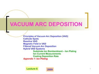
- 1. VACUUM ARC DEPOSITION Principles of Vacuum Arc Deposition (VAD) Cathode Spots Reactive VAD Magnetic Field in VAD Filtered Vacuum Arc Deposition Hybrid VAD Systems Substrate Ion Bombardment – Ion Plating Ion Current Measurements Coating Deposition Rate Appendix 1- Ion Plating Lecture 6 2009
- 11. VACUUM ARC PLASMA FROM CATHODE SPOTS TO THE SUBSTRATE VACUUM ARC DEPOSITION (VAD) Tracks of Cathode Spot Motion Multiple spots Ti, I arc ~100 A Single spot Cu, Iarc~30-50 A Plasma produced by a cathode spot Scheme of Cathodic Vacuum Arc Plasma Deposition
- 18. MACROPARTICLES IN VAD COATINGS
- 19. CURRENT-VOLTAGE CHARACTERISTICS OF A DISCHARGE TUBE
- 20. COMPARISON OF PLASMAS IN VACUUM ARC DEPOSITION AND SPUTTERING SYSTEMS: High voltage (few hundreds V - ~1 kV), low current (~10 -2 -1 A) discharge High current (I arc =30-500 A), low voltage (10-50 V) discharge Electrical characteristics Bombardment by of target by plasma ions to eject particles (atoms/molecules) of material to be deposited Production of charged particle jet to be deposited on substrate Function of plasma Glow discharge induced in low pressure background working gas Metal (mainly) plasma, cathode erosion species Type of plasma SPUTTERING VACUUM ARC FEATURE
- 21. COMPARISON OF PLASMAS (CONTINUE) 10 14 -10 18 10 16 -10 20 Plasma density, m -3 (3-6) 10 3 (Ar ions) (1-2) 10 4 Ion velocity, m/s 10-40 50-150 Ion energy, eV No Yes Macroparticles SPUTTERING VACUUM ARC FEATURE
- 32. COMMERCIAL VACUUM ARC DEPOSITION APPARATUS “Bulat-3” - NEW EPOCH IN CUTTING TOOL INDUSTRY (former USSR, 1981) Anode – water cooled vacuum chamber 3 independent plasma guns Chamber diameter ~ 60 cm
- 33. SCHEME OF COMMERCIAL VAD SYSTEM (“Bulat”- Type)
- 34. SCHEME OF COMMERCIAL TRIPLE CATHODE VAD SYSTEM
- 35. TRIPLE CATHODE VAD SYSTEM AT TAU
- 41. ION PLATING – SUBSTRATE BOMBARDMENT BY POSITIVE PLAMA IONS ION PLATING IN VAD Role of negative bias voltage on surface bombardment by plasma ions and coating deposition process
- 42. NEGATIVE BIAS VOLTAGE APPLIED TO THE SUBSTRATE IN VAD PROCESS Negative bias voltage to the substrate relative the grounded anode Substrate ion bombardment by positive metal ions
- 52. MEASUREMENT OF ION FLUX TO THE SUBSTRATE (ION CURRENT) Negatively biased Langmuir probe – saturation ion current measurement Saturation ion current characterizes deposition system effectiveness
- 53. VOLTAGE-CURRENT CHARACTERISTICS OF LANGMUIR PROBE Evaluation of deposition rate – saturated ion current is important
- 57. MAGNETIC FIELD IN VACUUM ARC PLASMA DEPOSITION SYSTEMS EDPL, TAU – System 3
- 65. SPOT MOTION ON ROUND CATHODE SURFACE (Ti arc, System 2) No magnetic field – random spot motion Acute angle directed outwards – Spot operation on the cathode side “ Arched” field – circumferential spot motion V. Zhitomirsky, JVST, 1995
- 67. “ ARCHED” FIELD - RECTANGULAR CATHODE DESIGH Magnetic field configuration: QuickField TM plot Cathode spot Motion track Rectangular cathode, System 4, EDPL
- 68. EFFECT OF “ACUTE ANGLE” IN CONE CATHODE DESIGN – SPOT CONFINEMENT IN CATHODE CENTER Cathode Anode Focusing Coil Guiding Coil Acute angle - between the magnetic line and cathode cone surface – spot motion towards the cathode center Axial magnetic field – spot confinement in the cathode center Cone cathode in axial field Cathode Coil
- 69. MAGNETIC PLASMA GUIDING TO THE SUBSTRATE IN THE STRAIGHT CYLINDRICAL DUCT Axial magnetic field produced by coils 2-4 positioned co-axially with duct axis - significant increase in plasma flux to the substrate System 3, EDPL
- 71. PRINCIPLES OF PLASMA GUIDING IN THE MAGNETIC FIELD PLASMA TRANSPORT IN THE STRAIGHT AND CURVILINEAR DUCT
- 80. VAD SYSTEM WITH A QUARTER -TORUS MAGNETIC FILTER Plasma flux is guided by toroidal magnetic field to the substrate positioned in the chamber, while macroparticles are fully or mainly removed from the flux System 2, EDPL
- 81. SCHEME OF FILTERED VAD (FVAD) SYSTEM (System 2 at TAU)
- 84. COATINGS DEPOSITED WITH UNFILTERED AND FILTERED VAD Macroparticles in Coating Unfiltered VAD Macroparticle-Free Coating Filtered VAD
- 90. SCHEME OF RECTANGULAR FVAD SYSTEM AND CATHODE APPLICATION: Transparent conducting SnO 2 coating deposition on flat substrates Rectangular cathode with cathode spot trace System 4, EDPL
- 93. COMPACT VAD SOURCE WITH CONE CATHODE, TAU, 2004-2008
- 96. Multi-Source VAD Systems Hybrid Deposition Systems
- 98. INDUSTRIAL SYSTEM WITH DUAL FILTERED VAD SOURCE V. Gorokhovsky, SCT 2004
- 100. HYBRID DEPOSITION SYSTEM BY V. GOROHOVSKY V. Gorokhovsky et. Al., SCT 1993 Substrate Filtered VAD Source E-Beam Source
- 101. LARGE HYBRID SYSTEM WITH VAD AND MAGNETRON SPUTTERING SOURCES CemeCon AG (Germany) By the courtesy of Dr. Christoph Shiffers (CemeCon AG), March 2009
- 106. CATHODIC SPUTTERING: DC TRIODE SYSTEM Negative bias voltage to the substrate – Sputter ion cleaning prior to deposition Negative bias voltage to the target – Sputter deposition