SlideShare una empresa de Scribd logo
1 de 2
Class No 09 Zunaib Ali
AssignementNo :01
DIFFERENCE BETWEEN FET & BJT ON THE BASIS OF
APPLICATIONS
Bipolar Junction Transistor Field Effect Transistor
1) A bipolar transistor requires a small
amount of current flowing to keep the
transistor on. While the current for one
transistor may be negligible, it adds up
when millions are switching
simultaneously. The heat dissipated on
bipolar limits the total number of
transistors that can be built on the chip
2) A BJT will consume more power in the
on- state.it cannot switch with less than
a 0.3V voltage drop.
3) BJT’s function as regulators of currents
as small current is regulating a large
current.
4) The bipolar transistor is liable for
thermal runway(over heating) due to a
negative temperature co-efficient.
5) BJTs are preferred for low current
applications.
6) BJTs have low-medium input
impedance(~1k -3k ohms).
7) BJTs are used where we need high
gain& fast response.
8) BJT's have a higher cutoff frequency
and a higher maximum current then
FET's.
1) Once the gate terminal on an FET has
been charged, no more current is
needed to keep that transistor on
(closed) for the duration of time
required.
2) FETs are preferred in Wide line or load
variations& have low power
consumption.
3) FET function as voltage regulators as
applied voltage on gate control the
output characteristics.
4) FET have a positive temperature co-
efficient, stopping thermal runway.
5) FETs are preferred in Low-voltage
applications ( less than 250V).
6) no current flows through the gate, the
input impedance of the FET is
extremely large (in the range of
1010
,1016
Ω). the large input impedance
of the FET makes them an excellent
choice for amplifier inputs.
7) FETs have low-medium gain.
8) FETs are preferred in High frequency
applications ( greater than 200kHz).
Class No 09 Zunaib Ali
9) To operate BJTs at high switching
frequencies & high current, we have to
prevent the devices from going into
haerd saturation as this will increase
storage times( making it difficult to
switch off quickly) but then cause the
device to dissipate more power due to
higher Vce-sat.
10) BJTs are relatively greater in size than
FET of same rating.
11) BJT is temperature sensitive at higher
level.
12) BJTs have high switching speed but
they are noisy also.
13) BJT Have small duty cycles.
9) FETs are low switching devices.FET is
therefore used for power switch design
and high power functions( less than
500W output power).
10) FET are smaller in size.so area
consumption of FET is less so Icsmade
by FETs provide higher packing
density as compared to BJTs.
11) FET is more stable to temperature &
therefore it is used in high temperature
applications.
12) As FET introduce lower noise level to
the system so where sensitivity to the
noise is very critcal and cannot be
neglected,JFET amplifiers are preferred
over BJT.
13) JFET used for micro wave
communication such as VHF, UHF
receivers.
14) FET's are easy to fabricate in large scale
and have higher element density the BJT's.
15) JFET is mostly used in digital circuits.
16) Switch mode power supplies (SMPS):
Hard switching above 200kHz
17) Switch mode power supplies (SMPS): ZVS
below 1000 watts

Más contenido relacionado

La actualidad más candente

La actualidad más candente (20)

Current and power using hall sensors
Current and power using hall sensorsCurrent and power using hall sensors
Current and power using hall sensors
 
Feedback amplifiers
Feedback amplifiersFeedback amplifiers
Feedback amplifiers
 
Light Emitting Diode Presentation Report
Light Emitting Diode  Presentation ReportLight Emitting Diode  Presentation Report
Light Emitting Diode Presentation Report
 
PPT ON POWER SYSTEM STABILITY
PPT ON POWER SYSTEM STABILITYPPT ON POWER SYSTEM STABILITY
PPT ON POWER SYSTEM STABILITY
 
Mosfet
MosfetMosfet
Mosfet
 
Microwave measurement
Microwave measurementMicrowave measurement
Microwave measurement
 
Gun diode
Gun diodeGun diode
Gun diode
 
Choppers
ChoppersChoppers
Choppers
 
Sample and hold circuit
Sample and hold circuitSample and hold circuit
Sample and hold circuit
 
Unit-1 Power Semiconductor devices
Unit-1 Power Semiconductor devicesUnit-1 Power Semiconductor devices
Unit-1 Power Semiconductor devices
 
Field Effect Transistor ppt
Field Effect Transistor pptField Effect Transistor ppt
Field Effect Transistor ppt
 
JFET
JFETJFET
JFET
 
Power BJT and Power MOSFET
Power BJT and Power MOSFETPower BJT and Power MOSFET
Power BJT and Power MOSFET
 
Op amp(operational amplifier)
Op amp(operational amplifier)Op amp(operational amplifier)
Op amp(operational amplifier)
 
Electrical drive unit 1 as per IP university_EEE
Electrical drive unit 1 as per IP university_EEEElectrical drive unit 1 as per IP university_EEE
Electrical drive unit 1 as per IP university_EEE
 
Filters
FiltersFilters
Filters
 
Tunnel Diode
Tunnel DiodeTunnel Diode
Tunnel Diode
 
Led Ppt
Led PptLed Ppt
Led Ppt
 
Rc and rl circuits
Rc and rl circuitsRc and rl circuits
Rc and rl circuits
 
Unit 3
Unit 3Unit 3
Unit 3
 

Destacado

Destacado (20)

Diodes,BJT,MOSFET,JFET
Diodes,BJT,MOSFET,JFETDiodes,BJT,MOSFET,JFET
Diodes,BJT,MOSFET,JFET
 
Mosfet
MosfetMosfet
Mosfet
 
3.bipolar junction transistor (bjt)
3.bipolar junction transistor (bjt)3.bipolar junction transistor (bjt)
3.bipolar junction transistor (bjt)
 
Metal Oxide Semiconductor Fet (Mosfet)
Metal Oxide Semiconductor Fet (Mosfet)Metal Oxide Semiconductor Fet (Mosfet)
Metal Oxide Semiconductor Fet (Mosfet)
 
Field-Effect Transistors
Field-Effect TransistorsField-Effect Transistors
Field-Effect Transistors
 
Mosfet
MosfetMosfet
Mosfet
 
FET (Field Effect Transistors)
FET (Field Effect Transistors)FET (Field Effect Transistors)
FET (Field Effect Transistors)
 
MOSFET AND JFET
MOSFET AND JFETMOSFET AND JFET
MOSFET AND JFET
 
Transistor , NPN & PNP Transistor
Transistor , NPN & PNP TransistorTransistor , NPN & PNP Transistor
Transistor , NPN & PNP Transistor
 
Transistors ppt by behin
Transistors ppt by behinTransistors ppt by behin
Transistors ppt by behin
 
Ppt on datalogger+digital modulation english
Ppt on datalogger+digital modulation englishPpt on datalogger+digital modulation english
Ppt on datalogger+digital modulation english
 
Embeded
EmbededEmbeded
Embeded
 
Ece
EceEce
Ece
 
20. b.e. ece syllabus
20. b.e. ece syllabus20. b.e. ece syllabus
20. b.e. ece syllabus
 
Jfet
JfetJfet
Jfet
 
Enero-junio 2016
Enero-junio 2016Enero-junio 2016
Enero-junio 2016
 
PUT (industrial electronic)
PUT (industrial electronic)PUT (industrial electronic)
PUT (industrial electronic)
 
Moore’s law
Moore’s lawMoore’s law
Moore’s law
 
Electronics
ElectronicsElectronics
Electronics
 
The Bible: The Canon of Scripture
The Bible: The Canon of ScriptureThe Bible: The Canon of Scripture
The Bible: The Canon of Scripture
 

Similar a FET vs BJT Comparison for Applications

IGBTprofessionalmaganementAssistantco.pdf
IGBTprofessionalmaganementAssistantco.pdfIGBTprofessionalmaganementAssistantco.pdf
IGBTprofessionalmaganementAssistantco.pdfEnricoFebrian
 
Body Heat Powered Flashlight Using LTC3108
Body Heat Powered Flashlight Using LTC3108Body Heat Powered Flashlight Using LTC3108
Body Heat Powered Flashlight Using LTC3108IJERA Editor
 
Field-Effect-Transistor.pptx
Field-Effect-Transistor.pptxField-Effect-Transistor.pptx
Field-Effect-Transistor.pptxSatyasis Mishra
 
Electron Tube Afs Epri R5
Electron Tube   Afs Epri R5Electron Tube   Afs Epri R5
Electron Tube Afs Epri R5John Kappenman
 
Bandgap Reference circuit Baased on FinFET Device
Bandgap Reference circuit Baased on FinFET DeviceBandgap Reference circuit Baased on FinFET Device
Bandgap Reference circuit Baased on FinFET DeviceYalagoud Patil
 
Analytical Modeling of Tunneling Field Effect Transistor (TFET)
Analytical Modeling of Tunneling Field Effect Transistor (TFET)Analytical Modeling of Tunneling Field Effect Transistor (TFET)
Analytical Modeling of Tunneling Field Effect Transistor (TFET)Abu Obayda
 
Selectii audio.pdf
Selectii audio.pdfSelectii audio.pdf
Selectii audio.pdfivan ion
 
A DC-6 GHz, Packaged 100 Watt GaN SPDT Switch MMIC
A DC-6 GHz, Packaged 100 Watt GaN SPDT Switch MMICA DC-6 GHz, Packaged 100 Watt GaN SPDT Switch MMIC
A DC-6 GHz, Packaged 100 Watt GaN SPDT Switch MMICSushil Kumar
 
High Frequency Transformer for Multi-Output SMPS Applications
High Frequency Transformer for Multi-Output SMPS ApplicationsHigh Frequency Transformer for Multi-Output SMPS Applications
High Frequency Transformer for Multi-Output SMPS ApplicationsKaushik Naik
 
Bipolar Junction Transistor (BJT) | Introduction | Operation | Uses
Bipolar Junction Transistor (BJT) | Introduction | Operation | UsesBipolar Junction Transistor (BJT) | Introduction | Operation | Uses
Bipolar Junction Transistor (BJT) | Introduction | Operation | UsesToukir Ahmed Chowdhury
 
igbt-140108131951-phpapp01.pdf
igbt-140108131951-phpapp01.pdfigbt-140108131951-phpapp01.pdf
igbt-140108131951-phpapp01.pdfsaranya575109
 
Ppt on power electronics
Ppt on power electronicsPpt on power electronics
Ppt on power electronicsShivani Mishra
 
Receiver structures(optical communication)
Receiver structures(optical communication)Receiver structures(optical communication)
Receiver structures(optical communication)shraddha bajaj
 
Balun and transformer core selection
Balun and transformer core selectionBalun and transformer core selection
Balun and transformer core selectionvilla1451
 
Chapter-4 FET (1).ppt
Chapter-4 FET (1).pptChapter-4 FET (1).ppt
Chapter-4 FET (1).pptJeelBhanderi4
 

Similar a FET vs BJT Comparison for Applications (20)

asas IGBT
asas IGBTasas IGBT
asas IGBT
 
IGBTprofessionalmaganementAssistantco.pdf
IGBTprofessionalmaganementAssistantco.pdfIGBTprofessionalmaganementAssistantco.pdf
IGBTprofessionalmaganementAssistantco.pdf
 
Body Heat Powered Flashlight Using LTC3108
Body Heat Powered Flashlight Using LTC3108Body Heat Powered Flashlight Using LTC3108
Body Heat Powered Flashlight Using LTC3108
 
Field-Effect-Transistor.pptx
Field-Effect-Transistor.pptxField-Effect-Transistor.pptx
Field-Effect-Transistor.pptx
 
Electron Tube Afs Epri R5
Electron Tube   Afs Epri R5Electron Tube   Afs Epri R5
Electron Tube Afs Epri R5
 
Bandgap Reference circuit Baased on FinFET Device
Bandgap Reference circuit Baased on FinFET DeviceBandgap Reference circuit Baased on FinFET Device
Bandgap Reference circuit Baased on FinFET Device
 
Analytical Modeling of Tunneling Field Effect Transistor (TFET)
Analytical Modeling of Tunneling Field Effect Transistor (TFET)Analytical Modeling of Tunneling Field Effect Transistor (TFET)
Analytical Modeling of Tunneling Field Effect Transistor (TFET)
 
Selectii audio.pdf
Selectii audio.pdfSelectii audio.pdf
Selectii audio.pdf
 
A DC-6 GHz, Packaged 100 Watt GaN SPDT Switch MMIC
A DC-6 GHz, Packaged 100 Watt GaN SPDT Switch MMICA DC-6 GHz, Packaged 100 Watt GaN SPDT Switch MMIC
A DC-6 GHz, Packaged 100 Watt GaN SPDT Switch MMIC
 
High Frequency Transformer for Multi-Output SMPS Applications
High Frequency Transformer for Multi-Output SMPS ApplicationsHigh Frequency Transformer for Multi-Output SMPS Applications
High Frequency Transformer for Multi-Output SMPS Applications
 
Bipolar Junction Transistor (BJT) | Introduction | Operation | Uses
Bipolar Junction Transistor (BJT) | Introduction | Operation | UsesBipolar Junction Transistor (BJT) | Introduction | Operation | Uses
Bipolar Junction Transistor (BJT) | Introduction | Operation | Uses
 
igbt-140108131951-phpapp01.pdf
igbt-140108131951-phpapp01.pdfigbt-140108131951-phpapp01.pdf
igbt-140108131951-phpapp01.pdf
 
Ba33301306
Ba33301306Ba33301306
Ba33301306
 
Ba33301306
Ba33301306Ba33301306
Ba33301306
 
Ppt on power electronics
Ppt on power electronicsPpt on power electronics
Ppt on power electronics
 
Ecl
EclEcl
Ecl
 
Receiver structures(optical communication)
Receiver structures(optical communication)Receiver structures(optical communication)
Receiver structures(optical communication)
 
Balun and transformer core selection
Balun and transformer core selectionBalun and transformer core selection
Balun and transformer core selection
 
54
5454
54
 
Chapter-4 FET (1).ppt
Chapter-4 FET (1).pptChapter-4 FET (1).ppt
Chapter-4 FET (1).ppt
 

Más de ZunAib Ali

Lcl filter design
Lcl filter designLcl filter design
Lcl filter designZunAib Ali
 
Power converter report
Power converter reportPower converter report
Power converter reportZunAib Ali
 
Performance of Six-Pulse Line-Commutated Converter in DC Motor Drive Application
Performance of Six-Pulse Line-Commutated Converter in DC Motor Drive ApplicationPerformance of Six-Pulse Line-Commutated Converter in DC Motor Drive Application
Performance of Six-Pulse Line-Commutated Converter in DC Motor Drive ApplicationZunAib Ali
 
SVM Simulation for three level inverter
SVM Simulation for three level inverterSVM Simulation for three level inverter
SVM Simulation for three level inverterZunAib Ali
 
Multi phase Star Rectifier
Multi phase Star Rectifier Multi phase Star Rectifier
Multi phase Star Rectifier ZunAib Ali
 
Space vector pwm_inverter
Space vector pwm_inverterSpace vector pwm_inverter
Space vector pwm_inverterZunAib Ali
 
Power transformer
Power transformerPower transformer
Power transformerZunAib Ali
 
Neutral point clamped inverter
Neutral point clamped inverterNeutral point clamped inverter
Neutral point clamped inverterZunAib Ali
 
7 channel Interleaved Boost Converter
7 channel Interleaved Boost Converter7 channel Interleaved Boost Converter
7 channel Interleaved Boost ConverterZunAib Ali
 
Sinusoidal PWM and Space Vector Modulation For Two Level Voltage Source Conve...
Sinusoidal PWM and Space Vector Modulation For Two Level Voltage Source Conve...Sinusoidal PWM and Space Vector Modulation For Two Level Voltage Source Conve...
Sinusoidal PWM and Space Vector Modulation For Two Level Voltage Source Conve...ZunAib Ali
 
Rectifiers Simulation
Rectifiers SimulationRectifiers Simulation
Rectifiers SimulationZunAib Ali
 
Instrumentational Amplifier
Instrumentational Amplifier Instrumentational Amplifier
Instrumentational Amplifier ZunAib Ali
 
Electronic Device pakages
Electronic Device pakagesElectronic Device pakages
Electronic Device pakagesZunAib Ali
 
Concept of energy transmission & distribution
Concept of energy transmission & distribution Concept of energy transmission & distribution
Concept of energy transmission & distribution ZunAib Ali
 
DC Motor Model
DC Motor Model DC Motor Model
DC Motor Model ZunAib Ali
 
High Voltage Dc (HVDC) transmission
High Voltage Dc (HVDC) transmissionHigh Voltage Dc (HVDC) transmission
High Voltage Dc (HVDC) transmissionZunAib Ali
 
Cambridge ielts 9 full
Cambridge ielts 9 fullCambridge ielts 9 full
Cambridge ielts 9 fullZunAib Ali
 
Water level buzzer
Water level buzzerWater level buzzer
Water level buzzerZunAib Ali
 
Fourier Specturm via MATLAB
Fourier Specturm via MATLABFourier Specturm via MATLAB
Fourier Specturm via MATLABZunAib Ali
 

Más de ZunAib Ali (20)

Lcl filter design
Lcl filter designLcl filter design
Lcl filter design
 
Power converter report
Power converter reportPower converter report
Power converter report
 
Performance of Six-Pulse Line-Commutated Converter in DC Motor Drive Application
Performance of Six-Pulse Line-Commutated Converter in DC Motor Drive ApplicationPerformance of Six-Pulse Line-Commutated Converter in DC Motor Drive Application
Performance of Six-Pulse Line-Commutated Converter in DC Motor Drive Application
 
SVM Simulation for three level inverter
SVM Simulation for three level inverterSVM Simulation for three level inverter
SVM Simulation for three level inverter
 
Multi phase Star Rectifier
Multi phase Star Rectifier Multi phase Star Rectifier
Multi phase Star Rectifier
 
Space vector pwm_inverter
Space vector pwm_inverterSpace vector pwm_inverter
Space vector pwm_inverter
 
Power transformer
Power transformerPower transformer
Power transformer
 
Neutral point clamped inverter
Neutral point clamped inverterNeutral point clamped inverter
Neutral point clamped inverter
 
7 channel Interleaved Boost Converter
7 channel Interleaved Boost Converter7 channel Interleaved Boost Converter
7 channel Interleaved Boost Converter
 
Sinusoidal PWM and Space Vector Modulation For Two Level Voltage Source Conve...
Sinusoidal PWM and Space Vector Modulation For Two Level Voltage Source Conve...Sinusoidal PWM and Space Vector Modulation For Two Level Voltage Source Conve...
Sinusoidal PWM and Space Vector Modulation For Two Level Voltage Source Conve...
 
Rectifiers Simulation
Rectifiers SimulationRectifiers Simulation
Rectifiers Simulation
 
Instrumentational Amplifier
Instrumentational Amplifier Instrumentational Amplifier
Instrumentational Amplifier
 
Electronic Device pakages
Electronic Device pakagesElectronic Device pakages
Electronic Device pakages
 
Inverter
InverterInverter
Inverter
 
Concept of energy transmission & distribution
Concept of energy transmission & distribution Concept of energy transmission & distribution
Concept of energy transmission & distribution
 
DC Motor Model
DC Motor Model DC Motor Model
DC Motor Model
 
High Voltage Dc (HVDC) transmission
High Voltage Dc (HVDC) transmissionHigh Voltage Dc (HVDC) transmission
High Voltage Dc (HVDC) transmission
 
Cambridge ielts 9 full
Cambridge ielts 9 fullCambridge ielts 9 full
Cambridge ielts 9 full
 
Water level buzzer
Water level buzzerWater level buzzer
Water level buzzer
 
Fourier Specturm via MATLAB
Fourier Specturm via MATLABFourier Specturm via MATLAB
Fourier Specturm via MATLAB
 

FET vs BJT Comparison for Applications

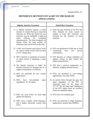
  • 1. Class No 09 Zunaib Ali AssignementNo :01 DIFFERENCE BETWEEN FET & BJT ON THE BASIS OF APPLICATIONS Bipolar Junction Transistor Field Effect Transistor 1) A bipolar transistor requires a small amount of current flowing to keep the transistor on. While the current for one transistor may be negligible, it adds up when millions are switching simultaneously. The heat dissipated on bipolar limits the total number of transistors that can be built on the chip 2) A BJT will consume more power in the on- state.it cannot switch with less than a 0.3V voltage drop. 3) BJT’s function as regulators of currents as small current is regulating a large current. 4) The bipolar transistor is liable for thermal runway(over heating) due to a negative temperature co-efficient. 5) BJTs are preferred for low current applications. 6) BJTs have low-medium input impedance(~1k -3k ohms). 7) BJTs are used where we need high gain& fast response. 8) BJT's have a higher cutoff frequency and a higher maximum current then FET's. 1) Once the gate terminal on an FET has been charged, no more current is needed to keep that transistor on (closed) for the duration of time required. 2) FETs are preferred in Wide line or load variations& have low power consumption. 3) FET function as voltage regulators as applied voltage on gate control the output characteristics. 4) FET have a positive temperature co- efficient, stopping thermal runway. 5) FETs are preferred in Low-voltage applications ( less than 250V). 6) no current flows through the gate, the input impedance of the FET is extremely large (in the range of 1010 ,1016 Ω). the large input impedance of the FET makes them an excellent choice for amplifier inputs. 7) FETs have low-medium gain. 8) FETs are preferred in High frequency applications ( greater than 200kHz).
  • 2. Class No 09 Zunaib Ali 9) To operate BJTs at high switching frequencies & high current, we have to prevent the devices from going into haerd saturation as this will increase storage times( making it difficult to switch off quickly) but then cause the device to dissipate more power due to higher Vce-sat. 10) BJTs are relatively greater in size than FET of same rating. 11) BJT is temperature sensitive at higher level. 12) BJTs have high switching speed but they are noisy also. 13) BJT Have small duty cycles. 9) FETs are low switching devices.FET is therefore used for power switch design and high power functions( less than 500W output power). 10) FET are smaller in size.so area consumption of FET is less so Icsmade by FETs provide higher packing density as compared to BJTs. 11) FET is more stable to temperature & therefore it is used in high temperature applications. 12) As FET introduce lower noise level to the system so where sensitivity to the noise is very critcal and cannot be neglected,JFET amplifiers are preferred over BJT. 13) JFET used for micro wave communication such as VHF, UHF receivers. 14) FET's are easy to fabricate in large scale and have higher element density the BJT's. 15) JFET is mostly used in digital circuits. 16) Switch mode power supplies (SMPS): Hard switching above 200kHz 17) Switch mode power supplies (SMPS): ZVS below 1000 watts