Industrial compressor
•Download as PPTX, PDF•
10 likes•3,193 views

Industrial Compressor - Operation and Maintenance

Recommended
More Related Content
What's hot
What's hot (20)
Similar to Industrial compressor
Similar to Industrial compressor (20)
Recently uploaded
Recently uploaded (20)
Industrial compressor
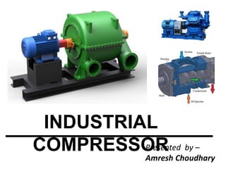
- 1. INDUSTRIAL COMPRESSORPresented by – Amresh Choudhary
- 2. Pump and a Compressor • Moving hydraulic fluid through a system requires either a pump or compressor. Both achieve this goal, but through different operating methods. • Pumps have the ability to move liquids or gases. • Compressors typically only move gas due to its natural ability to be compressed. Pumps and compressors both have very high pressure rises. • The primary purpose of an air compressor is to take in air and compress it to decrease its volume and increase its energetic potential.
- 3. Why compressed air? • One of the major methods of actuation of industrial machines is pneumatic actuation, ie, action by compressed air. It is nothing but air, at a pressure higher than the atmospheric pressure • It has been widely used as an energy source for operating simple to sophisticated equipments in mechanical, chemical and other process industries.
- 4. Even though air is the most abundant natural resource on the planet, compressed air is one the most expensive of services to provide. The following properties of compressed air justify why it’s such an important energy source: Elastic nature (which permits internal storage of energy) Non toxicity Low viscosity (compared to other working fluids) No appreciable corrosive nature (increased life of equipments) Why compressed air?
- 5. working principle An air compressor is basically a device that converts power (usually from an electric motor, a diesel engine or a gasoline engine) into kinetic energy by compressing and pressurizing air. This compressed air can be stored, or can be released in quick bursts, on command. Compressors work on two parallel principles:
- 6. WORKING PRINCIPLE Compressors work on two parallel principles: Ideal gas law states that, for any state of an ideal gas, PV = mRT Where, P = absolute pressure of gas V = volume occupied by the gas T = absolute temperature of gas m = amount of substance present in the gas R = universal gas constant Therefore, to increase pressure of a gas, one has to either decrease the volume it occupies, or increase its temperature, or both. Invariably, compression of air creates heat, and the air is warmer after compression.
- 7. DO YOU KNOW In industry, compressed air is so widely used that it is often regarded as the fourth utility, after electricity, natural gas and water About 8 - 10% of all electrical power used in an industry is employed in the process of compressing air
- 8. DO YOU KNOW Air compressors are machines with very low overall efficiency; only 10-30% of the energy supplied to the compressors reaches the point of end use. The remaining power is converted to unusable heat energy, and to a smaller extent, is lost in friction, misuse, and noise.
- 9. TYPES OF COMPRESSOR Positive Displacement: The principle of compression in this type of compressors is by decreasing the volume. For gases, as volume decreases, pressure increases known as compression. Dynamic Compressors: In these compressors, the gases are first accelerated i.e. velocity is increased, then its made to flow through increasing cross section area, where kinetic energy is converted into pressure energy i.e. pressure is increased.
- 10. POSITIVE DISPLACEMENT COMPRESSORS In these compressors, pressure of the air is increased by reducing its volume, in accordance with the ideal gas law.
- 12. POSITIVE DISPLACEMENT COMPRESSORS Positive displacement compressors causes movement by trapping a fixed amount of air then forcing (displacing) that trapped volume into the discharge pipe. It can be further classified according to the mechanism used to move air. Rotary Compressor Reciprocating compressor
- 13. ROTARY COMPRESSORS The gas is compressed by the rotating action of a roller inside a cylinder. The roller rotates off-centre around a shaft so that part of the roller is always in contact with the cylinder. Volume of the gas occupies is reduced and the refrigerant is compressed. High efficient as sucking and compressing refrigerant occur simultaneously.
- 14. ROOTS BLOWER The roots blower consists of two lobe For higher pressure ratio three and four lobes may be used here the pressure of air delivered is slightly above the atmosphere. The machine consists of a fixed casing two shafts fitted with two lobe rotors one of the rotor is driven by electric motor or other prime movers and other is driven through the gears from first.
- 15. VANE TYPE COMPRESSOR / BLOWER This type of compressor is shown inn fig. The compressor is consists of rotor drum mounted eccentrically in the cylindrical casing. The rotor is provided with vanes in the slots. These vanes or blades are made from non-metallic material usually fiber or carbon. The vanes can slide in and out in the slots. The volume between two vanes keeps on changing due to eccentric motion of the rotor. The rotation of the rotor causes space to be created between the vanes, the rotor and casing. The space is connected to suction pipe so that air enters into the created space and filled.
- 16. VANE TYPE COMPRESSOR / BLOWER Due to rotation of vanes air is delivered to the receiver. In this type of compressor. the total pressure rise is partially due to internal compression between the vanes and partially due to back flow of air from receiver
- 17. SCREW TYPE COMPRESSOR Screw type 2 stage screw type
- 18. RECIPROCATING COMPRESSOR It is a positive-displacement compressor that Uses pistons driven by a crankshaft to deliver gases at high pressure. The intake gas enters the suction manifold, then flows into the compression cylinder It gets compressed by a piston driven in a reciprocating motion via a crankshaft, Discharged at higher pressure
- 21. RECIPROCATING COMPRESSOR CYLINDERS: Cylinders of the reciprocating compressor are used in the process industries are separable from the frame. They are attached to the frame by way of an intermediate part known as the distance piece. The cylinder will accommodate the both suction and discharge valve plates. PISTON: The piston is the heart of the reciprocating compressor. The piston translates the energy from the crankcase to the gas in the cylinder. In order to avoid the leakage of compressed gas between the piston and cylinder, the piston is equipped with a set of sliding seals called as piston rings. Usually, the rings are made of a material, that having self-lubricating property to reduce the slide friction force between the cylinder and the piston. This to avoid the wear in the cylinder wall and also increase eciency by reducing the friction force. For lubricated service, metallic rings such as cast iron or bronze as well as non-metallic materials such as filled nylon are used
- 22. RECIPROCATING COMPRESSOR PISTON ROD: The piston rod is threaded to the piston and transmits the reciprocating motion from the crosshead to the piston. The piston rod is normally constructed of alloy steel and must have a hardened and polished surface particularly where it passes through the cylinder packing (double-acting cylinders). Rod loading must be kept within the limits set by the compressor vendor because overloading can cause excess run-out of the rod resulting in premature packing wear. This, in turn, leads to leakage, reduced efficiency, and increased maintenance expense. DISTANCE PIECE: The distance piece is a separable housing that connects the cylinder to the frame. The distance piece may be open or closed and may have multiple compartments. It may be furnished as single, double, or extra long. The purpose of a longer distance piece is to isolate that part of the piston rod entering the crankcase and receiving lubrication from the part entering the cylinder and contacting the gas. This prevents lubricant from entering the cylinder and contaminating the gas, particularly necessary in non-lubricated cylinders. It can also keep a synthetic lubricant in a cylinder.
- 23. RECIPROCATING COMPRESSOR The packing rings are the heart of rod packing assembly. The main packing rings types are Tangent Ring Radial Ring or Pressure Breaker Ring Backup ring CRANKSHAFT: Larger compressors, normally above 150 kW(200 hp), have forged steel crankshafts. for compressor less than or equal to 150kW machines ductile iron crankshaft. Crankshafts should have removable balance weights to compensate for rotary unbalance as well as reciprocating unbalance. The crankshaft should be dynamically balanced when above 800 rpm
- 24. RECIPROCATING COMPRESSOR BEARING: The main and connecting rod bearings should be split-sleeve, steel-backed, babbitted insert type. Antifriction bearing shall be used for compressor rating less than 150kW. As per API 618 trapper roller bearings are used as the main bearing for compressor rating less than 150kW. CONNECTING ROD: For reciprocating compressor of above 150 kW(200 hp), have forged steel connecting rod are used and for compressor less than or equal to 150kW machines ductile iron material is used. Like Crankshafts, the connecting rod should have drilled hole for oil passage. The connection rod is used to connect the crankshaft and the crosshead. The connecting rod converts the rotary motion into reciprocating motion. The connecting rod bolts and nuts shall be securely locked with cotter pins or wire after assembly
- 25. RECIPROCATING COMPRESSOR CROSS HEAD: All industrial reciprocating compressors are equipped with Crosshead. The crosshead is used to guide the piston in the cylinder bore. The following are the advantage of crosshead The compressor can use a narrow piston, due to the use of narrow piston larger valve area for greater efficiency. Permits a longer stroke and greater capacity. Separates crankcase from the cylinder, allowing control of oil carryover into the cylinder. Gives greater stability to piston, eliminating piston “slap” and reducing ring wear VALVE: The reciprocating compressor cylinder valves are of the spring-loaded, gas-actuated type. Reciprocating compressors generally use one of three types of valve configurations: Ring Type valve Poppet Type valve Plate Type valve
- 26. WHAT ARE DYNAMIC COMPRESSORS? The dynamic compressor is continuous flow compressor is characterized by rotating impeller to add velocity and thus pressure to fluid. It is widely used in chemical and petroleum refinery industry for specific services. There are two types of dynamic compressors Centrifugal Compressor Axial Flow Compressor
- 28. CENTRIFUGAL COMPRESSOR Achieves compression by applying inertial forces to the gas by means of rotating impellers. It is multiple stage ; each stage consists of an impeller as the rotating element and the stationary element, i.e. diffuser Fluid flow enters the impeller axially and discharged radially The gas next flows through a circular chamber (diffuser), where it loses velocity and increases pressure. Demo
- 39. AXIAL FLOW COMPRESSOR Working fluid principally flows parallel to the axis of rotation. The energy level of air or gas flowing through it is increased by the action of the rotor blades which exert a torque on the fluid Have the benefits of high efficiency and large mass flow rate Require several rows of airfoils to achieve large pressure rises making them complex and expensive Demo
- 40. WHY MULTISTAGE COMPRESSOR? High temp rise leads into limitation for the maximum achievable pressure rise. Discharge temperature shall not exceed 150ºC and should not exceed 1350C for hydrogen rich services A multistage centrifugal compressor compresses air to the required pressure in multiple stages. Intercoolers are used in between each stage to removes heat and decrease the temperature of gas so that gas could be compressed to higher pressure without much rise in temperature Intercooler
- 41. HOW TO SELECT A PARTICULAR TYPE OF COMPRESSOR ?
- 42. Graph showing operating regions of various compressors Taken from PIP REEC001 Compressor Selection Guidelines
- 43. Table showing operating conditions of various compressors Taken from PIP REEC001 Compressor Selection Guidelines
- 44. Capacity and Pressure Range of various compressors
- 45. Advantages and Disadvantages of dynamic compressors Advantages Disadvantages Dynamic Compressors Centrifugal •Wide operating range •High reliability •Low Maintenance •Instability at reduced flow •Sensitive to gas composition change Axial •High Capacity for given size •High efficiency •Heavy duty •Low maintenance •Low Compression ratios •Limited turndown
- 46. Advantages and disadvantages of positive displacement type compressor Advantages Disadvantages Positive displacement compressor Reciprocating •Wide pressure ratios •High efficiency •Heavy foundation required •Flow pulsation •High maintenance Diaphragm •Very high pressure •Low flow •No moving seal •Limited capacity range •Periodic replacement of diaphragm Screw •Wide application •High efficiency •High pressure ratio •Expensive •Unsuitable for corrosive or dirty gases
- 47. Pressure drop in compressor
- 48. SAFETY CONSIDERATION IN SELECTION Safety attributes that should be considered in the selection of compressor systems include: a. Limiting gas properties (e.g., decomposition, flammability, toxicity). Normal compressor operation should not violate these limiting gas properties. b. Compatibility of process gas with materials of construction (e.g., H2S with copper, ethylene oxide with brass, oxygen) c. Containment, collection and disposal of seal and vent gases d. Over-pressure protection e. Process and economic issues listed below should also be evaluated for safety implications
- 49. SITE AND LOCATION The most common, but important location, attributes that should be considered in the selection of compressor systems include: a. Available utilities b. Accessibility to services and support c. Environmental conditions Depending on the application, other location variables may have to be considered as well The relative importance of the location variables should also be established to ensure that the best type and size of compressor is selected.
- 50. LUBRICATION SYSTEMS • Compressors typically require oil for bearing lubrication and bearing cooling. Oil is supplied by the lubrication system.
- 51. Components in a lubrication system should include: a. Oil reservoir or tank b. Lube oil pump or pumps c. Oil filters d. Oil coolers e. Associated piping and instrumentation LUBRICATION SYSTEMS
- 52. Lubrication systems downstream of the filter should be constructed of stainless steel. (Lubrication systems constructed completely of stainless steel eliminate many potential contamination issues caused by corrosion of non-stainless steel components) If carbon steel components are used, provision for cleaning and passivating such as a flushing jumper, should be included. LUBRICATION SYSTEMS
- 53. LUBRICATION - CENTRIFUGAL COMPRESSORS Lubrication oil is required for fluid film and rolling element journal and thrust bearings. Lubrication oil is supplied from a reservoir by a lube oil pump. The pump may be compressor shaft-driven or independent. An independent main oil pump and an auxiliary oil pump should be preferred for centrifugal compressors.
- 54. LUBRICATION - CENTRIFUGAL COMPRESSORS The major lubricated components in a centrifugal compressor include: • Driver • Electric motor • Turbine • Coupling • Compressor • Radial bearings • Sleeve • Tilt pad radial • Thrust bearings • Angular contact ball • Tilt pad
- 55. LUBRICATION - CENTRIFUGAL COMPRESSORS Centrifugal compressors can have large lubrication systems consisting of Oil reservoir Pump Filter Cooler Oil lines. The oil is then pumped to the lubricated parts, which are both radial and thrust bearings. Most Preferred Oil : ISO 32 Turbine oil / ISO 46 ISO 68 turbine oil If a step-up gear is present and lubricated with the same oil as the bearings,
- 56. LUBRICATION - CENTRIFUGAL COMPRESSORS Seal-oil system Some compressors rely on a seal-oil system along with a seal at the end of the shaft to prevent gas from leaking beyond it. This is particularly true when compressing environmentally toxic gases. A seal-oil system consists of an oil-collection area, oil supply-line with a check valve, oil return-line, gas return-line, head tank and a seal-oil reservoir. During operation, oil is pumped via the oil supply-line through the seal. Because the pressure of the oil is greater than the pressure of the gas, the oil flowing through the seal keeps the gas from leaking. Oil (carrying the absorbed gas) is pumped to a compartment in the reservoir, at which point the gas is separated and returns to the compressor. The gas-free oil then returns to the seal-oil system. As a safety precaution in the event of pump failure, a separate head tank supplies enough oil on a pump shutdown to allow the compressor to be shut down without a gas leak. Most seal-oil systems use the same oil to lubricate the bearings. The oil from the head tank is NOT used to lubricate the bearings.
- 57. LUBRICATION - CENTRIFUGAL COMPRESSORS Bearings—both radial and thrust—on axial compressors are lubricated with high-quality ISO 32 turbine oil.
- 58. The major factors involved in the selection of compressor lubricants include: • Type, size and speed of compressor • Gas being compressed • Number of stages • Pressure and temperature at each stage • Environment • Type of lubrication system selection of compressor lubricants
- 59. • Lubrication : oil type • Oil viscosity can vary widely based on The type of Gas compressed and The desired discharge pressure • The major lubrication areas and components on a compressor are as follows: Compressor Frame :Rust- and oxidation-inhibited (R&O) oil (usually an ISO VG of 150/ ISO 100 – Main bearings – Connecting rod bearings – Cross head bearings – Motor bearings Cylinder Region For Inert Gas / Moderate pressure ( > 1000 psi) : ISO 150 R&O – Rider bands As pressure increases to 5000 psi ISO 150 to ISO 680 – Compression rings – Packing – Valves LUBRICATION - RECIPROCATING COMPRESSORS
- 60. • if the frame bearings and cylinder are using the same oil for lubrication, the oil is pumped from a reservoir where the oil is filtered and cooled. The oil is distributed to the bearings in the frame by an oil pump. The same oil is also used, by way of injectors, to lubricate and seal piston rings. In many cases, two different lubricants are used. The frame bearings don’t require synthetics because of the moderate conditions. High-pressure, high- temperature conditions may require synthetics or compounded oils in the cylinder. Also, higher pressures require higher viscosities. A separate oil system is used to supply oil to the injectors for the cylinder. Too much oil in the cylinder can create problems, such as carbonizing the valves. It is better to under-lubricate than over-lubricate. One quart of oil will lubricate the sweep of the piston over 10,000,000 ft2. The following is the formula to calculate the oil required in quarts/day. This is an average amount—it can change based on operating conditions and gas being compressed:
- 64. DAILY CHECKSHEET Record operating air inlet, inter stage and discharge pressures and temperatures. Record cooling water inlet and outlet pressures and temperatures. Record lubricant Lubrication system • Pressure and temperatures • External surfaces wiped clean • Proper oil level in oil reservoir • Proper oil color • No mist from ejector system • No oil cooler water leaks • No oil leaks Gear case • External surfaces wiped clean • No unusual noise or vibrations • No oil leaks • No water leaks • Vibration level
- 65. DAILY CHECKSHEET Intercoolers and after cooler • External surfaces wiped clean • Condensate drains functioning properly • No cooling water leaks • No air leaks Compressor Drive Motor • External surfaces wiped clean • Properly ventilated • No erratic or noisy operation • No frayed or worn electrical cables Record all vibration levels. Check air-inlet filter differential pressure. Check proper operation of drain traps. Drain control air filter. Check for leaks, air, water, and lubricant. Repair and clean as necessary. Check lubricant sump level and adjust as necessary. Check drive motor for smooth operation and record amps
- 66. EVERY 3 MONTHS • Check lubricant filter differential pressure. Replace element as necessary. • Check lubricant sump venting system. Replace filter elements as necessary. • Check operation of capacity control system. • Check operation of surge control system. • Check main-drive motor amps at full-load operation. • Check automatic drain traps and strainers. Clean and/or replace as necessary
- 67. EVERY 6 MONTHS • Check air-inlet filter and replace element as necessary. • Take oil sample for analysis. Replace lubricant as necessary.
- 68. ANNUALLY • Inspect intercooler, after cooler, and lubricant cooler. Clean and/or replace as necessary. • Inspect main drive motor for loose mounting bolts, frayed or worn electrical cables, and accumulated dirt. Follow manufacturer’s recommendations, including lubrication. • Inspect main drive coupling for alignment and required lubrication. • Inspect gearbox for loose mounting bolts, vibration, unusual noise or wear and axial clearances per manufacturer’s manual. • Check impeller inlets and diffusers for signs of wear, rubbing or cracking. • Check control panel for complete and proper operation. • Check all control valves for proper operation. • Check all safety devices for proper settings and operation. • Inspect check valve; replace worn parts.
- 70. • Check compressor lubricant level in crankcase and cylinder lubricator and, if necessary, add to level indicated by sight gauge. • Check cylinder lubrication feed rate and adjust, as necessary. • Check lubricant pressure and adjust as necessary to meet specified operating pressure. • Check cylinder jacket cooling water temperatures. • Check capacity control operation. Observe discharge pressure gauge for proper LOAD/UNLOAD pressures • Drain control line strainer. • Check operation of automatic condensate drain trap (intercooler and aftercooler). • Drain condensate from discharge piping as applicable (dropleg and receiver). • Check intercooler pressure on multi-stage machines, and refer to manufacturer’s manual if pressure is not as specified. DAILY CHECKSHEET
- 71. • Check piston rod packing for leaks and for blow-by at gland. Repair or replace as necessary per manufacturer’s manual. • Inspect lubricant scraper rings for leakage. Replace as necessary per manufacturer’s manual. • Inspect air intake filter. Clean or replace as necessary. • Drain lubricant strainer/filter sediment. • Lubricate unloader mechanism per manufacturer’s manual. • Check motor amperes (amps) at compressor full capacity and pressure. EVERY 3 MONTHS
- 73. TROUBLE PROBABLE CAUSE Low discharge pressure and air delivery. Restricted air inlet filter or suction line. Bad compressor valves or valve unloading mechanism. Leaks in the plant air system at fittings, connections, tools, etc. Unloader pilot set wrong or bad. Pressure switch set wrong or bad. Drive belt slipping. Incorrect speed. Worn piston rings or loose piston. Leaking head gasket. Drain valve open. Bad pressure gauge. Demand exceeds capacity, compressor not sized properly. Safety valve leaking. Loose compressor valves or leaking at valve gaskets. Valves or piston rings not seated.
- 74. TROUBLE PROBABLE CAUSE Water in the crankcase Compressor does not run long enough to get hot and vaporize the moisture squeezed out of the air during compression. Compressor may be too large for the application. Leaking cylinder head. Detergent oil being used. System pressure leaking back through valve. Rusty valves and/or cylinders. Compressor operated too infrequently. Compressor does not run enough to get hot and vaporize the moisture squeezed out of the air during compression. Not properly processed for storage.
- 75. TROUBLE PROBABLE CAUSE Excessive belt wear. Pulleys out of alignment. Belt too loose or too tight. Belt slipping. Pulley wobbling. Pulley groove damaged or rough. Excessive vibration. Incorrect speed. Compressor valves not functioning properly. Pulley loose. Motor or engine out of balance. Compressor, motor or engine not secured tightly, or tightened in a bind. Excessive discharge pressure Compressor loads and unloads excessively Air storage capacity too small. Compressor valves or unloaders bad. Excessive system leakage. Incorrect speed. Unloader pilot differential set too close.
- 76. TROUBLE PROBABLE CAUSE Air receiver pressure excessive. Air pressure gauge inaccurate. Leaks in unloader piping system. Compressor valve unloader bad. Unloader pilot or pressure switch set improperly, or bad. Compressor overheats. Defective compressor valves. Pressure setting too high. Clogged Intercooler, internally or externally. Inadequate ventilation or recirculation of hot air. Pulley rotation wrong. Incorrect speed. Running clearances insufficient, piston to cylinder wall or running gear. Lubrication inadequate.
- 77. TROUBLE PROBABLE CAUSE Compressor knocks. Head clearance insufficient. Piston loose in cylinder bore, cylinder bore worn, piston or piston rings worn Worn connecting rod bearings Worn main bearings Excessive crankshaft end play Pulley loose Compressor valve assemblies loose High air discharge temperature Compressor valve assemblies bad. Air discharge pressure too high. Inadequate ventilation or hot air recirculating. Cooling surfaces of compressor or Intercooler excessively dirty. Ambient temperature too high. Scored or excessively worn cylinder walls.
- 78. TROUBLE PROBABLE CAUSE Compressor overheats. Defective compressor valves. Pressure setting too high. Clogged Intercooler, internally or externally. Inadequate ventilation or recirculation of hot air. Pulley rotation wrong. Incorrect speed. Running clearances insufficient, piston to cylinder wall or running gear. Lubrication inadequate. Compressor knocks Head clearance insufficient. Piston loose in cylinder bore, cylinder bore worn, piston or piston rings worn. Worn connecting rod bearings. Worn main bearings. Excessive crankshaft end play. Pulley loose. Compressor valve assemblies loose.
- 79. TROUBLE PROBABLE CAUSE High air discharge temperature Compressor valve assemblies bad. Air discharge pressure too high. Inadequate ventilation or hot air recirculating. Cooling surfaces of compressor or Intercooler excessively dirty. Ambient temperature too high. Scored or excessively worn cylinder walls Air receiver pressure excessive. Air pressure gauge inaccurate. Leaks in unloader piping system. Compressor valve unloader bad. Unloader pilot or pressure switch set improperly, or bad.
- 80. TROUBLE PROBABLE CAUSE High air discharge temperature Compressor valve assemblies bad. Air discharge pressure too high. Inadequate ventilation or hot air recirculating. Cooling surfaces of compressor or Intercooler excessively dirty. Ambient temperature too high. Scored or excessively worn cylinder walls Excessive current draw. Low voltage. Loose electrical connection. Wire size too small. Motor too small. Air discharge pressure too high .Bearings tight or seizing. No crankshaft endplay. Compressor speed too high. Motor bad. Compressor not unloaded
- 81. TROUBLE PROBABLE CAUSE Failure to start. Power not on. Blown circuit fuse or circuit breaker tripped. Thermal motor overload tripped. Low voltage. Faulty start switch. Power failure. Pressure switch misadjusted or inoperable. Loose or broken wire. Motor bad. Compressor not unloading. Probable Cause Excessive oil consumption.