SlideShare a Scribd company logo
1 of 43
Download to read offline
INFLUENCE LINES 383
CHAPTER TEN
10. INFLUENCE LINES
This is also another very useful technique in classical structural analysis. Influence lines are
plotted for various structural effects like axial forces, reactions, shear forces, moments and thrust etc. As
structural members are designed for maximum effects, ILD’ s help engineer decide the regions to be
loaded with live load to produce a maxima at a given section.
“ An influence line is a graphical representation of variation of a particular structural effect at a
given section for all load positions on its span.”
Two methods, viz, static method and virtual displacement method are used for the construction
of ILD’ s. Mostly it is the later method which is prefered. All structures in general and Railway and
Highway bridges in particular are frequently subjected to various types of moving loads. As influence
lines describe variation at a particular section for all load positions on span, the effects of moving loads
can be calculated very easily. It must be remembered that a system of moving loads moves as a unit. For
Railway bridges standard cooper’ s E-60 and E-72 loadings are used whereas for highway bridges
AASHTO lane loadings and truck loadings or sometimes tank loadings are used. When dealing with
calculations regarding moving loads the problem is how to place the system so as to produce maximum
effects at a given section. Sometimes mathematical criteria are used for the live load purpose and
sometimes simple inspection is made. In each case influence lines help us simplify the things.
10.1. Statical Method of Constructing Influence Lines
In this method, a load may be placed at several positions within span/(s) and a mathematical
expression for a particular structural effects at a section is set-up. By placing limits of X (the distance),
the shape and ordinates of influence lines (called influence co-efficients also) can be determined.
For example consider the cantilever loaded below and let moment at fixed end A be represented
by its influence line.
For a generalized load position as defined by distance X in the diagram, moment at A is.
BA
P
X
l
L
I.L.D. for Ma
Ma = − P (L − X) 0 < X < L
Minus sign with P shows a negative moment at A for all load positions (consider sign
convention for moments)
384 THEORY OF INDETERMINATE STRUCTURES
For X = 0 (load at point B) moment at A is − PL. Influence co-efficient is L at B. If X = L
load is at A so moment at A is zero. Influence co-efficent is zero. In between A and B, moment at A
varies linearly, joining the points, ILD for Ma is obtained. Now even if several loads are placed on the
cantilever, Ma is simply the sum of all loads when multiplied by corresponding ordinates.
If a cantilever supports a ud.l, the above I.L.D for Ma is applicable. Consider a strip of width
dX located at a distance X from free end,
w
A
wdX
b
L
X
dX
y
L - X
Ma =
b
∫
o
WydX = w
b
∫
o
ydX
Where
b
∫
o
ydX is area of I.L.D between limits zero to b.
10.2. Influence Lines for beam Reactions:
ILD’ s for reactions in case of simple beams and compound beams (determinate beams resting
over several supports) can be drawn by using the already described procedure. Consider a simple beam
with a single load sitting at any moment of time as shown
From statics it can be shown that
BA
P
X
L
Ra =
PX
L
Rb =
P(L - X)
L
(L - X)
L
yi l
I.L.D. for Rb
I.L.D. for Ra
l
yi
X/L
Ra =
PX
L
and Rb = P



L − X
L
0 < X < L
INFLUENCE LINES 385
When X = 0 (load at B); Ra = 0 and Rb = P (by putting limits in above expressions)
When X = L (load at A); Ra = P and Rb = 0 (by putting limits in above expressions)
Instead of maximum co-efficients equal to P it is costomary to have them equal to 1 so that these
could be evaluated by the product of loads and respective ordinates and these diagrams become valid for
several loads. So algebraically
Ra = ∑ Pi yi
Rb = ∑ Pi yi
10.3. Principal of Virtual Displacements:
Consider a simple beam under the action of load P as shown. Ra can be found by virtual
displacements by imagining that support at A has been removed and beam is under the action of load P
and Ra. Under the action of Ra, beam is displaced as A/
B. The virtual work equation is
BA
P
X
L
Ra
y
A
/
Ra × AA/
− Py = 0 (Force × displacement)
So Ra =
Py
AA/ where y is the displacement due to Ra under P.
If AA/
= 1, Ra = Py A result already obtained.
This procedure of drawing ILDs’ is more useful for the complicated cases.
10.4. Reactions for Compound Beams:
A beam resting over several supports which has been made determinate by the availability of
inserted hinges at suitable points is called a compound beam. The following Rules must be kept in mind
while constructing ILD’ s for such cases.
1. Points of I.L.D corresponding to supports should show zero displacement except where
virtual displacement is given (in case of reactions).
2. Portion of the beam between hinges which are straight before virtual displacements should
remain straight after virtual displacement.
3. If a beam is continuous over two consecutive support and there is a hinge after these two
supports, that portion of beam behaves a unit in case the virtual displacement is given
elsewhere.
4. Portions of beam between pins which is straight before virtual displacement, shall remain
386 THEORY OF INDETERMINATE STRUCTURES
straight after virtual displacement.
Considering these guidelines given, draw influence lines for reactions for the following beam.
I. L. D for Ra
I. L. D for Rb
I. L. D for Rc
I. L. D for Rd
I. L. D for Re
I +
+ I
+ I
+
+ I
+
+ I
A F B G C H D E
If positive areas of above diagrams are loaded, upward reactions at corresponding support will
occur or vice-versa.
Construct Influence lines for reactions for the following compound beam by virtual
displacements.
INFLUENCE LINES 387
I. L. D for Ra
I. L. D for Rb
I. L. D for Rc
I. L. D for Rd
I. L. D for Re
I +
+ I
+ I
+
+I
+
I
A G B H C I D E J F
+
I. L. D for Rf
I
Evaluation of maximum upward and down reaction due to concentrated loads and udl can be
done by using the basic principles described already.
If several moving loads, from right to left direction, approach left hand support of a simple
beam, the left reaction continues to increase and becomes maximum till leading wheel is at the left
support. This corresponding first maxima will decrease immediately if the load falls off and leaves the
span from left upon further advance, reaction at left support will start increasing and will become
maximum again when second wheel is at the left support. So there will be as many maxima as is the
number of loads.
Evaluation of reactions due to live load udl is rather simple as the span portion required to be
loaded for maximum upward and downward support reactions are obvious by the simple inspection. Of
course positive areas if loaded will give maximum upward reactions and vice-versa.
388 THEORY OF INDETERMINATE STRUCTURES
10.5. Influence Lines for Shear Force:
In structural analysis, normally we develop the methods by considering simple cases and some
generalized conclusions are drawn which can then be applied to more complicated cases. So consider the
following simple beam wherein a moving load (right to left) occupies the position shown at any instant of
time.
Using left-up and write-down as sign convention for positive shear force.
A
P
X
B
C
a b
Ra Rb
For all load positions to right of point C, the shear force for at C (Vc) is equal to + Ra.
Vc = Ra
It means that for load position between point B and C, the Shape of ILD for SF at C will be the
same as the shape of ILD for + Ra.
For all load positions to left of point C, the shear force at C (Vc) is equal to − Rb.
Vc = − Rb
It means that for load position between point A and C, the shape of ILD for SF at C will the
same as shape of ILD for −Rb. Knowing that positive ILD is drawn above the reference line and negative
ILD is drawn below the reference line, we obtain the ILD for Vc as shown below with the help of ILD’ s
for reactions (+ Ra1 − Rb)
A
P
X
B
C
a b
Ra Rb
L
l b/L
a/L
+
l
I. L. D. for + Ra
I. L. D. for - Rb
I. L. D. for Vc
INFLUENCE LINES 389
Mathematically
Ra =
PX
L
0 < X < L
Rb = P
(L − X)
L
0 < X < L
At X= 0, load is at B and Vc is zero. At x= b, load is at C and Vc = + Ra =
Pb
L
or
b
L
if P= 1.
The ordinates
a
L
and
b
L
can be obtained by using similar triangles. Now inspect the ILD for Vc.
For a right to left advance of load system, Vc keeps on increasing till the “ leading load is at the
section” , when leading load just crosses the section, Vc drops by the magnitude of load and this process
continues. So we can write that for maximum SF at a section, “ the load should be at that section” . This
is the first criterion of calculation of Vmax. Now the question comes to mind that which load among the
moving load system should be placed at the section? To address this question, we have noted, that change
in SF at a section, ∆V, is equal to change in Ra (∆Ra) minus the load leaving the Section. (Pn)
So, ∆V = ∆Ra − Pn
If W is sum of all the loads on the span L before advance of a, it can be shown that
∆Ra =
Wa
L
So, ∆V =
Wa
L
− Pn
Any load which reverses this expression, should be brought back and placed at that section to
realize the maximum SF at that section. So a change in the sign of above expression can be regarded as
the second criterion for maximum shear force at a section.
It can also be shown that loads entering or leaving the span as a result of any particular advance
do not affect the above expression very significantly.
The above method is called the statical method. The same shape of ILD for Vc can be obtained
by virtual displacement method also.
A B
C
a b
Ra RbL
b/L
a/L
+ I. L. D. for Vc
V V
390 THEORY OF INDETERMINATE STRUCTURES
Now imagine that resistance to vertical displacement at C has been destroyed (imagine a sort of
cut at the section) and the vertical shear force as shown (opposite to sign convention for positive shear
force). The area enclosed between the original position before virtual displacement and the deformed
position after virtual displacement is the ILD for Vc.
10.6. Influence Line Diagrams for Bending Moment:
Again we consider the simple beam under the action of a simple moving load as shown. Let it be
required to construct ILD for Mc.
A
P
X
B
C
a b
Ra Rb
L
I. L. D. for Mc
ab/L
ILD for Ra x a
ILD for Rb x b
+
a
b
If the load is between points B and C.
Mc = Ra × a =
PX
L
× a 0 < X < b
at X = 0; load at B, Mc = 0.
If X = b;
Mc =
Pab
L 


=
ab
L
if P = 1
It means that for portion BC, the shape of ILD for Mc is the same as the shape of ILD for Ra
multiplied by distance a.
If the load is between points A and C
Mc = Rb × b =
P(L − X)
L
× b b < X < L
At X = b, load is at C; , Mc = Rb × b
So Mc =
Pab
L 


=
ab
L
if P = 1
INFLUENCE LINES 391
It means that for portion AC, the shape of ILD for Mc is the same as the shape of ILD for Rb
multiplied by b.
At X = L;
Load at A; Mc = 0
The same shape of ILD for Mc can be obtained by virtual displacements also.
A
P
X
B
C
a b
I. L. D. for Mcy
M M
a
b
Ra Rb
dx
M M
Idealized section at C
before virtual displacements
Section at C after virtual
displacement
The virtual work equation is
work done by loads = work done by the moments.
P × y = M × δθ.
Or M =
Py
δθ
So, if δθ = 1; the moment at Section C for a single load system will be load multiplied by
corresponding influence ordinate (influence co-efficient) while constructing ILD’ s by virtual
displacements, loads are not considered. Now construct ILD for Mc by virtual displacements.
At Section C, we imagine that the beam resistance to moments which produce rotations has been
destroyed while resistance to shear and axial loads is intact. This situation is obtained by considering that
at Section C; there is a sort of hinge (one degree of freedom system). On this hinge the moments are
392 THEORY OF INDETERMINATE STRUCTURES
applied on two sides of hinge as shown alone. The segments of beam rotate and the displaced beam
position is ILD for Mc.
The one-degree of freedom system such as a hinge is further explained in diagrams shown which
illustrate the movement. This procedure can now be applied to more complicated cases where statical
approach may be laborious.
The method of virtual displacements can be applied to more complicated cases like compound
beams etc., by considering the basic ideas established in this chapter.
A
+
++
+
E B C F D
1 2 3
1 2 3
ILD for M1 - 1
ILD for M2 - 2
ILD for M3 - 3
10.7. Evaluation of Mmax at a Section
In case of a simple beam supporting a moving load system, the maximum moment at a section is
obtained when
1. One of the loads is at the section.
2. In case of several moving loads, that load shall be placed at the Section, for producing
maximum moment at that Section, which reverses the average loading on two portions of
span adjacent to Section.
INFLUENCE LINES 393
Average loading on any portion =
sum of all loads on that portion
length of portion
10.8. Absolute Maximum bending Moment
In case of a series of moving loads traverse on a beam, the absolute maximum bending moment
occurs near the mid span under the adjusted position of that load which gave us maximum bending
moment at mid span. Procedure is as follows:
1. Apply the criteria of maximum bending moment at mind span to find the load which is to
be placed at mid span.
2. For this position of loads find the position of resultant of all loads on span.
3. Move the system slightly so that mid-span is bisected by the resultant of all loads on span
and the load which gives us maximum bending moment at mid-span.
4. Find absolute maximum bending moment. It will occur under displaced position of that
load which gave us maximum bending moment at mid-span.
Considering that invariably loads would be magnified for design purpose and appreciating that
the numerical difference between the values of maximum mid-span bending moment and absolute
maximum bending moment is insignificant, evaluation of absolute maximum bending moment for a given
moving load system appears to be of theoretical interest only. How interested students can evaluate it for
only moving load system by considering the above four points and guidelines contained in this chapter.
10.9. Girders with Floor beams (Panelled girders)
Normally in bridge construction, moving loads are hardly applied to the main girders directly
but instead following arrangement is used for the load transfer.
The moving load system comes on the stringers which transfer it to the main girder through
floor beams in form of concentrated loads (Reactions of floor beams). So main girder is subjected to
concentrated loads only. For large spans the main girder may be of steel, poured in-situ reinforced
concrete or pre-stressed concrete. Points a, b, c, …. F are called panel points and the distance between
any two panel points is called a panel.
With the above mentioned load-transfer mechanisms, it can be easily seen that ILD’ s for main
reactions remain same as that for a simple beam as discussed already.
394 THEORY OF INDETERMINATE STRUCTURES
As there will be no load on the main girder except floor beam reactions, it is stated that for a
given load position, the shear force within a panel remains constant so we can talk of shear force in
panels rather that shear force at a section (panel and becomes a section). Let us now construct ILD’ s
for shear force for various panels of girder already shown.
INFLUENCE LINES 395
4/5 ILD for + Ra
ILD for Vab
ILD for Vef
( + )
( - )
ILD for + Ra
ILD for - Rb
( - )
( + )
0.4
0.4
ILD for Vcd
ILD for - Rb
ILD for Rb x b
ILD for Ra x a
3a/5
b/5
yb yc+
a
b
ILD for Mmn
d x 4d
5d
6
d
5
2d x 3d
5d
=
+
ILD for Mc
I
I
A five panels main girder is shown for which various ILD’ s have been sketched.
396 THEORY OF INDETERMINATE STRUCTURES
10.10. ILD For Vab (ILD for shear in end panel)
If a load P is placed at a distance X from panel point b, then reactions at panel points a and b
will be
PX
d
and
P(d − X)
d
respectively.
Pa = Panel point load at a or reaction of floor beam at a =
Px
d
, 0 < X < d
Pb = Panel poiint load at b or reaction of floor beam at b =
P(d − X)
d
0 < X < d.
if X = 0, load P will be at b, then Pa = 0 and Pb = P
if X = d, load P will be at a, then Pa = P and Pb = 0 So, Vab ≡ 0
In between a and b, shear force varies linearly.
Now inspect the shape of ILD for Vab, it resembles with the shape of ILD for moment at point b
considering the panelled girder as a simple beam. So to evaluate (Vab)max, criteria of max bending
moment at a section b (reversal of average loading expression) will be applied.
10.11. ILD for Vef (ILD for shear in other end panel)
The construction of ILD for Vef is same as that for Vab and same arguments apply. Inspecting
this diagram, it is clear that the shape resembles with ILD for bending moment at e if panelled girder
was treated as a simple beam. So to evaluate (Vef)max, the criteria for maximum bending at point e shall
be applied.
10.12. ILD for Ved (ILD for shear in intermediate panel)
Considering the load P on panel cd acting at a distance X from panel point d.
Pd = Panel point load at d or floor-beam reaction at d =
P(d − X)
d
, 0 < X < d.
Pc = Panel point load at c or floor-beam reaction at c =
P(X)
d
, 0 < X < d.
If load is to right of d; Vcd = + Ra So, ILD for Vcd for this region will be the same as that for
Ra. If load is to left of C, Vcd = − Rb. So for this region shape of ILD for Vcd will be the same as the
shape of ILD for − Rb. Now third possibility is load actinig on span CD itself as shown.
Inspecting the expressions for panel point loads at d and c stated above, we observe that the
shear Vcd within the panel varies linearly. So joining the ordinates under points C and D by a straight
line will complete ILD for Vcd.
10.13. Evaluation of (Vcd)max (Maximum shear force in intermediate panel)
If a moving load is advanced at point d in a direction from right to left, considering W/
is
resultant of all loads on span CD, the following criteria can be easily developed as a consequence of
variation of shear force is panel CD due to an advance.
W
L
>
W/
d
Any load which reverses the above criteria shall give (Vcd)max.
INFLUENCE LINES 397
10.14. ILD for Mmn
Section mn is located within panel bc. Same technique can be applied for constructing ILD for
Mmn. If load P is to right of panel point C.
Mmn = Ra × a.
It means that if load is between points c and f, the shape of ILD for Mmn will be the same as
shape of ILD for Ra multiplied by a. If load P is to left of panel point b, then.
Mmn = Rb × b.
It means that if load is between points a and b, then shape of ILD for Mmn will be the same as
shape of ILD for Rb multiplied by b. Now consider load within panel bc with P acting at a distance
X from c.
Pb =
PX
d
and Pc =
P(d − X)
d
0 < X < d.
then Mmn = Pb yb + Pc yc =
PX
d
yb +
P(d − X)
d
yc 0 < X < d.
So between the panel, the moment varies linearly. Therefore joing the ordinates of ILD for Mmn
at b and c by a straight line, we complete the ILD for Mmn.
Now it is understood that SF is generally maximum near the support while moment is generally
maximum near the mid-span. So ILD for Mmn can also be used to evaluate corresponding maxima. If
criteria of maximum bending moment is applied at a section corresponding to bigger ordinate, then
(Mmn)max can be calculated for a moving load system.
10.15. ILD for Mc
At the panel points, the load is directly transmitted to the main girder and the panel girder
behaves as a simple beam at the panel points. So ILD for Mc will be drawn considering the girder as a
simple beam.
10.16. Influence Lines for axial forces in Truss Members:
As before, let us consider a simple case of parallel chord truss carrying loads at its lower chord.
The conclusions obtained are general and can be extended to non-parallel chord trusses.
398 THEORY OF INDETERMINATE STRUCTURES
1
2
3
4
A
G C F E
D
B
h
( - )
( + )
( + )
( - )
( + )
I
θ
θ
ILD for S1
When a moving load system traverses the bottom chord of this trussed bridge, it is known that
forces in top chord members will be compressive in nature while that in bottom chord will be tensile in
nature. The forces in chord members are a function of moment divided by truss height. For a chord
member take “ moment at the point where other two members completing the same triangle meet divided
by height of truss.” This has already been established in this book when discussing method of moments
and shears. So applying this S1 is a compressive force, so assigned a negative sign, equal to moment at C
divided by the height of truss. So considering the truss as a simple beam, draw an ILD for Mc and divide
it by the height of Truss. (S1)max can be evalutated by applying the criteria of maximum bending moment
(Average loadings) at point C considering the truss as a simple beam.
INFLUENCE LINES 399
ILD for S3
It is a tensile force equal to moment at D divided by height of Truss. (S3)max can be evalauted by
applying the criteria of maximum bending moment at point D.
ILD for S2
It is known that axial force in an inclined member is
± V
± Cosθ
. Minus before Cosθ shall be taken
if the angle “ between inclined member and vertical” is counterclockwise. Now if the load is right of D,
SF applicable to member 2 is + Ra. So corresponding portion of ILD for + Ra is taken. This is divided
by − Cosθ. If the load is to left of C, SF applicable to member 2 is − Rb. So corresponding portion of
ILD for − Rb is taken. This is again divided by − Cosθ. In between the panel SF varies linearly so we
can join the corresponding points.
The shape of ILD for S2 resembles with the shape of ILD for intermediate panel shear in a
panelled girder. So (S2)max can be evaluated by applying the criteria of maximum intermediate panel
shear.
ILD for S4
If the load is at E or right of E, Force in member 4 is zero and if load is at or to left of point C,
again the force in member 4 is zero. If the load is at F, the same will be the tensile force in member.
Using these boundary conditions, ILD for S4 is constructed. Now inspect its shape. It resembles with the
shape of ILD for moment at F (or D) in an equivalent simple beam of span CE. So (S4)max can be
evaluated by applying the criteria of maximum bending moment (average loading criteria) at F (or D).
10.17. Influence lines for moment and horizontal thrust in a three hinged arch.
We know that H =
µc
yc
and
Mx = µx − Hy.
Where y will be the rise of arch at a distance X from origin (usually a support).
400 THEORY OF INDETERMINATE STRUCTURES
y yc
x
C
A
H
B
H
L
Va Vb
x(L - x)
L
Ly
4yc
L
4yc
( + )
( + )
( - )
ILD for H
ILD for Mx
( + )
Shaded area
Influence line for any structural effect can be drawn by following the formula for that structural
effect.
10.17.1. ILD for horizontal thrust H
Horizontal thrust H is developed at the springings (supports) of an arch. Examine the formula
for H



H =
µc
yc
. So ILD for H will be obtained if ILD for moment at centre is drawn, considering the
arch to be a simple bam, and is then divided by yc. The peak ordinate of ILD for H will be
L
µyc
. (H)max
due to a moving load system can be obtained by applynig the criteria of maximum bending moment at the
centre.
10.17.2. ILD for Moment in the arch
From the Eddy’ s theorem we know that bending moment in the arch at a distance x from
support is
Mx = µx − Hy
where µx = simple span bending moment at a distance X.
INFLUENCE LINES 401
So as a first step, we construct ILD for simple span bending moment at a distance X. Then we
subtract the ILD for Hy. The net area between these two diagrams is the ILD for moment in the arch as
shown.
10.18. Standard Leadings
For the design of Railway bridges standard Cooper’ s E-60 and E-72 loadings consisting of two
locomotives each weighing 213 tons on 18 axles each followed by infinite udl representing compartments
is considered. Structural affects obtained for a E loading can be used to get the same for another E
loading by simply multiplying them with the ratio of E loadings.
Original E-60 or E-72 loadings are in kip-ft. system as follows:
15
↓ 8/
30
↓ 5/
30
↓ 5/
30
↓ 5/
30
↓ 9/
4 of 19.5
↓ 5 ↓ 6 ↓ 5 ↓ 8/
15
↓ 8/
4 of 30
↓ 5/
↓ 5/
↓ 5/
↓ 9/
4 of 19.5
↓ 5/
↓ 6/
↓ 5/
↓ 5/
3/ft
Above wheel loads are in kips per rail or tonnes per track. (1 Ton = 2 Kips ; small ton)
Converting E-72 loading in SI Units we have IK = 5 KN approximately.
80 KN
↓ 2.44
4 of 160 KN
↓ 1.52 ↓ 1.52 ↓ 1.52 ↓ 1.52 ↓ 2.74
4 of 104 KN
↓ 1.52 ↓ 1.83 ↓ 1.52 ↓ 2.44
80
↓ 2.44
4 of 104 KN
↓ 1.52 ↓ 1.52 ↓ 1.52 ↓ 2.42
4 of 104 KN
↓ 1.52 ↓ 1.83 ↓ 1.52 ↓ 1.52
53 KN/m
Cooper’ s E-72 loading in SI-units is shown above and E-60 below:
66.75
↓ 2.44
4 of 133.5 KN
↓ 1.52 ↓ 1.52 ↓ 1.52 ↓ 2.74
4 of 86.77 KN
↓ 1.52 ↓ 1.83 ↓ 1.52 ↓ 2.44
66.75
↓ 2.44
4 of 133.5 KN
↓ 1.52 ↓ 1.52 ↓ 1.52 ↓ 2.74
4 of 86.77 KN
↓ 1.52 ↓ 1.83 ↓ 1.52 ↓ 1.52
43.8 KN/m
Distance between loads is in meters.
For highway bridges AASHTO HS24-44 loading is internationally considered and it consists of
a Tractor and Semi-trailer with three axles carrying 0.2W, 0.4W and 0.4W respectively. These loads
when converted into kips are 16k, 32k and 32k. Standard AASHTO lane loading is probably 100 lbs/ft2
.
However, in our country, due to circumstances 70 ton tank loading or Truck-train loading
described in Pakistan Highway code can be used.
We shall use railway loadings only. Let us solve some typical problems now.
Example No.1: In a girder with Floor beams having five equal panels of length 9 meters each.
Determine (a) Maximum positive and negative end panel shears. (b) Maximum Shear in the first
intermediate panel from left hand end. The live load is Coopers E-72 loading.
402 THEORY OF INDETERMINATE STRUCTURES
( + )
( - )
( - )
( + )
ILD for Vab
ILD for Vef
ILD for Vbc
0.80
0.6
0.2
0.80
SOLUTION: 1. Maximum positive End Panel Shears (Vab)max
Advance loads at section B and use criteria
W/
d
<
W
L
Portion ab Portion bf
80
9
<
2498.87
45
after 1st advance.
240
9
<
2338.87
45
after 2nd advance
400
9
<
2178.87
45
after 3rd advance
560
9
>
2018.87
45
after 4th advance.
It means that once 3rd load of 160 KN crosses point b, the criterion is reversed so for maximum
end panel shear, 3rd load of 160 KN should be placed at point b. Now place the system of loads
accordingly and compute corresponding ordinates.
INFLUENCE LINES 403
3.52 2.44 1.52 1.52 1.52 2.74 1.52 1.83 1.52 2.44 2.44 1.52 1.52 1.52 2.44 1.52 1.83 1.52 1.52
1 2 3 4 5 6 7 8 9 10 11 12 13 14 15 16 17 18 19 8.6 m
4 of 160 4 of 104 4 of 160 4 of 104
8080
y1
y4
y19
0.8
ILD for Vab
Ordinates Under Loads:
y1 = 0.3128 y2 = 0.5297 y3 = 0.6648
y4 = 0.80 y5 = 0.766 y6 = 0.7053
y7 = 0.6715 y8 = 0.6308 y9 = 0.597
y10 = 0.5428 y11 = 0.488 y12 = 0.4548
y13 = 0.421 y14 = 0.387 y15 = 0.333
y16 = 0.299 y17 = 0.2586 y18 = 0.2248
y19 = 0.191
(Vab)max = 80 × 0.3128 + 160 (0.5297 + 0.6648 + 0.8 + 0.766)
+ 104 (0.7053 + 0.6715 + 0.6308 + 0.597)
+ 80 × 0.5428 + 160 (0.488 + 0.4548 + 0.421 + 0.387)
+ 104 (0.333 + 0.299 + 0.2586 + 0.2248) +
1
2
× 8.6 × 0.191 × 53
= 25.024 + 441.68 + 271.62 + 43.42 + 280.128 + 116 + 43.52
= 1221.4 KN.
Similarly (Vef)max = -1145 KN (Do the Process yourself)
We have to observe a similar Process for evaluation of (Vef)max as was used for (Vab)max. The
loads will be advanced at point e and average loadings on portions ae and ef will be compared. The
404 THEORY OF INDETERMINATE STRUCTURES
load which produces reversal after advance should be brought back and placed at section e for (Vef)max.
Evaluation of (Vbc)max
1 2 3 4 5 6 7 8 9 10 11 12 13 14 15 16 17 18
4 of 160 4 of 104 4 of 160 4 of 104
8080KN
y1
y4
y18
0.6
0.82m
f
y14
e
d
y5
+
c
ba
ILD for Vbc
( )-
0.2
2.25 6.75m
I.L.D for Vbc
Once loads are advanced from right to left at C, the following criteria shall be used to evaluate
maximum intermediate panel shear (Vbc)max
W
L
>
W/
d
Portion bc portion cf
80
9
<
2064
45
after 1st advance.
240
9
<
2168
45
after 2nd advance
400
9
<
2272
45
after 3rd advance
560
9
>
2315.46
45
after 4th advance.
So maximum positive SF in panel bc will be obtained when 3rd wheel of 160 KN is placed at
point c. Now place loads as shown above and determine corresponding ordinates of ILD. Multiply loads
and ordinates by giving due care to signs of ILD, we obtain (Vbc)max.
Now from similar triangles, influence co-efficients y1,...... y18 are:
y1 = 0.113 y2 = 0.33 y3 = 0.465
y4 = 0.6 y5 = 0.566 y6 = 0.505
y7 = 0.472 y8 = 0.431 y9 = 0.397
y10 = 0.343 y11 = 0.289 y12 = 0.255
y13 = 0.221 y14 = 0.187 y15 = 0.126
INFLUENCE LINES 405
y16 = 0.093 y17 = 0.052 y18 = 0.018
So, (Vbc)max = 80 × 0.113 + 160 (0.33 + 465 + 0.6 + 0.566)
+ 104 (0.505 + 0.472 + 0.431 + 0.397) + 80 × 0.343
+ 160 (0.289 + 0.255 + 0.221 + 0.187)
+ 104 (0.126 + 0.093 + 0.052 + 0.018)
(Vbc)max = 720.34 KN
EXAMPLE NO.2: Determine the maximum bending moment at a cross-section 9.1m from left hand for
a beam of span 27.3m. The moving live load is 117 KN/m having a length of 6m.
SOLUTION:
Sketch ILD for moment at the indicated section.
Now let us assume that the given position of Udl gives us(Mc)max at a distance X from C as
shown. Determine Ra for this position
∑Mb = 0
Ra × 27.3 = 702 (3 + 12.2 + X)
406 THEORY OF INDETERMINATE STRUCTURES
Ra = 390.84 + 25.71 X
Moment at C = Mc = Ra × 9.1 −
117 X2
2
Mc = (390.84 + 25.71) 9.1 −
117 X2
2
Simplify
Mc = 3556.64 + 233.96 X − 58.5 X2
If BM at C is maximum, then
d Mc
dX
= Vc = 0
233.96 X − 2 × 58.5 X = 0
X = 2m
Now compute y1 and y2 from similar triangles of ILD
18.2
27.3
=
y1
7.1
→ y1 = 4.733 m
9.1
27.3
=
y2
14.2
→ y2 = 4.733 m
So (Mc)max = ud.l × area of ILD Under UDL
= 117 (6 × 4.733 +
1
2
× 6 × 1.327)
= 3788.3 KN-m
INFLUENCE LINES 407
EXAMPLE NO. 3:
Calculate maximum bending moment at Section mn and pq of a five panel bridge. Each panel is
of 9m.
Five loads of 160 KN each spaced at 1.52m travel from right to left.
1.52 1.52 1,521.52
160 160 160 160 160
8.1
6.3
y2
y1 y4
y3
5 of 160
ILD for Mmn
ILD for Mpq
99
Evaluation of (Mmn)max
It is recommended that criteria of maximum bending moment be applied at maximum ordinate of
8.1 corresponding to Panel point C. Now comparing average loadings on portion ac and cf, we find that
3rd load reverses the criterion as it crosses. So it must be placed at point C. Determine ordinates
408 THEORY OF INDETERMINATE STRUCTURES
8.1
27
=
y3
25.48
→ y3 = 7.644, y4 = 7.188, y1 = 6.3 + 1.496 = 7.796
y2 = 6.3 + 1.192 = 7.492
(Mmn)max = 160 (7.492 + 7.796 + 8.1 + 7.644 + 7.188) = 38.22 × 160
= 6115.2 KN-m
The reader is also suggested to calculate (Mmn)max. by coinciding the resultant of moving load
system with the maximum ordinate. Place the loads accordingly. Compute influence co-efficients and
multiply loads with respective ordinates to compute (Mmn)max. Compare this value with the previous one.
(Mpq)max
As ILD for Mpq is symmetrical about centre-line (mid span), Arrange the loads such that the
resultant falls on mid-span. All five loads shall be accommodated and will have an ordinate of 9.
(Mpq)max = 160 (9 + 9 + 9 + 9 + 9) = 7200 KN-m
Important:
The instructor is advised to work with lesser number of loads, usually five to seven, in the class
and Establish the procedure. The students can then be given assignments involvinig standard trains etc.,
for clarification of their concepts.
EXAMPLE NO. 4:
A simple beam has a clear span of 27.5 m. Construct ILD for SF at a section 6.1m from left
support. How should Coopers-E-60 loading be placed to calculate maximum shear force at this section?
SOLUTION:
Draw ILD for Vc. Advance the loads at section C. We shall show the load position required for
(Vc)max only.
( - )
( + )
66.75
4 of 133.5 4 of 86.77 3 of 133.5
66.75
1.28 m
CA B
6.1 m 21.4 m
0.778
y1
y2
y9
y12
ILD for Vc
0.222
Computing influence co-efficients y1......y12 from similar triangles.
INFLUENCE LINES 409
y1 = − 0.133, y2 = 0.722, y3 = 0.667,
y4 = 0.612, y5 = 0.512 y6 = 0.4566,
y7 = 0.3901, y8 = 0.335, y9 = 0.246,
y10 = 0.157 y11 = 0.10, y12 = 0.0466
In order to have (Vc)max, at least one load should be at C. To decide which load should be placed
at C, reversal in the sign of following equation is sought.
∆V =
Wa
L
− Pn
W = Sum of all the loads on span before advance.
a = any particular Advance
L = Span
Pn = magnitude of Load crossing the section due to an advance.
____
For the first advance
∆V =
1281.58 × 2.44
27.5
− 66.75 = + 46.96 KN.
It shows that SF at C has increased due to 1st advance.
____
For second advance.
∆V =
1415 × 1.524
27.5
− 133.5 = − 55.08 KN.
It shows that if second advance at C is made, Vc decreases. So for (Vc)max, position
before 2nd advance (after 1st advance) is required. For this position above influence co-efficients have
been computed.
(Vc)max = 66.75 (− 0.133) + 133.5 (0.778 + 0.722 + 0.667 + 0.612)
+ 86.77 (0.512 + 0.4566 + 0.3901 + 0.335)
+ 66.75 (0.246) + 133.5 (0.157 + 0.1 + 0.046)
= 567.37 KN
EXAMPLE NO. 5:- Calculate the maximum bending moment at the points C and D if five loads of
410 THEORY OF INDETERMINATE STRUCTURES
160 KN each spaced at 1.52 m cross-the bean from right to left.
CA B
7 m 7 m 14 m
5.25
y1 y2 y3 y4 y5
(+)
1.521.521.521.521.52
5 of 160 KN
y1 y2 y3 y4 y5
(+)
ILD for Mc
ILD for Md
D
MCMax
Line-up all loads upto point C (theoretically slightly to right of C). Give advances at point C and
compare average loading in portion AC and BC due to various advances.
Portion Ac Portion Bc
160
7
<
4 × 160
21
after 1st advance.
2 × 160
7
>
3 × 160
21
after 2nd advance.
So, as the second load of 160 KN crosses ponit C, reversal is obtained. So for (Mc)max, this load
INFLUENCE LINES 411
should be brought back and placed at C (position before 2nd advance or after 1st advance). Compute
influence co-efficients.
y1 = 4.11, y2 = 5.25, y3 = 4.87
y4 = 4.49, y5 = 4.11
(Mc)max = 160 (4.11 + 5.25 + 4.87 + 4.49 + 4.11) = 3652.8 KN-m
(Md)max
This section is mid span of beam. Clearly applying the criteria of maximum bending moment at
D (comparing Average loadings on AB and BD), we get
Span AD Span BD
160
14
<
4 × 160
14
after 1st advance
2 × 160
14
<
3 × 160
14
after 2nd advance
3 × 160
14
>
2 × 160
14
after 3rd advance.
So position before 3rd advance (or after 2nd advance) will give us (Md)max. Place the loads
accordingly and compute influence co-efficients.
y1 = y5 = 5.48 y2 = y4 = 6.24 y3 = 7
So, (Md)max = 160 (5.48 + 6.24 + 7 + 6.24 + 5.48)
= 4870.4 KN-m
EXAMPLE NO.6:
Calculate maximum axial forces induced in members 1, 2, 3 and 4 of truss already shown if five
loads of 150 KN each spaced at 1.52m corsses at the bottom chord from right to left. Take h = 2m and
span = 5d = 10 meters.
412 THEORY OF INDETERMINATE STRUCTURES
SOLUTION:
The corresponding ILD’ s for S1.....S4 have already been plotted. Now we will use those
diagrams to calculate maxima. See the Truss of article 9.16.
160
( + )
( + )
( - )
1.521.521.521.52
5 of 160 KN
1.521.521.521.52
5 of 160 KN
1 m
1 m
+0.565
( + )
1.52 1.53
y1 y3
INFLUENCE LINES 413
S1max.
The shape of ILD for S1 resembles with the shape of ILD for Mc in an equivalent simple beam.
So giving advances at C (now forget the truss and play with ILD’ s only). Apply the criterion for
maximum moment at C.
Portion Ac Portion Bc
160
4
<
4 × 160
6
after 1st advance.
2 × 160
4
=
3 × 160
6
after 2nd advance.
Considering equality as a reversal, S1max will be obtained for position before second advance (or
after 1st advance). Place loads accordingly and compute influence co-efficients.
y1 = .744, y2 = 1.2 y3 = 0.896
y4 = 0.592 y5 = 0.288
So, S1max = 160 (0.744 + 1.2 + 0.896 + 0.592 + 0.288)
= − 595.2 KN (It is a compressive force)
S3max
Inspect the shape of ILD for S3. It resembles with the shape of ILD for moment at D
considering the truss to be a simple beam. So apply the criterion of maximum moment at D.
Portion AD Portion BD
160
6
<
3 × 160
4
(last load not on span) after 1st advance.
2 × 160
6
<
3 × 160
4
After 2nd advance.
3 × 160
6
=
2 × 160
4
After 3rd Advance.
So for S3max, position before 3rd advance is valid (After second advance). Place the loads
accordingly and compute influence co-efficients.
y1 = 0.592, y2 = 0.893, y3 = 1.2,
y4 = 0.744, y5 = 0.288
(S3)max = 160 (0.592 + 0.893 + 1.2 + 0.744 + 0.288)
= 594.72 KN (It is a tensile force).
S2max
Inspect the shape of ILD for S2. It resembles with the shape of ILD for as shear force in a
intermediate panel of a panelled girder. So for evaluating S2max, we apply the criterion of maximum
intermediate panel shear. Advance is made at D or F.
W/
d
<
W
L
160
2
=
5 × 160
10
after 1st advance.
So for S2max, the leading load should be placed at maximum ordinate, only three loads will be
414 THEORY OF INDETERMINATE STRUCTURES
acting on portion BD.
y1 = − 0.565 y2 = − 0.3503 y3 = − 0.1356
(S2)max = 160 (− 0.565 − 0.3503 − 0.1356)
= − 168.144 KN (It is a compressive force)
S1max
y1 = y3 = 0.24 y1 = 1
S1max = 160 (0.24 + 1 + 0.24)
= 236.8 KN (It is a tensile force)
10.19. Influence Lines for Statically Indeterminate Structures:
The same procedure can be adopted for constructing ILDs’ for indeterminate structures.
However, compatibility and redundants have to be considered as demonstrated earlier.
INFLUENCE LINE DIAGRAM FOR INDETERMINATE BEAMS(By method of virtual displacement)
Influence line diagram for Shear.
In virtual work for shear the B.M. does not do any work only shear force does the work.
Case 1: Let us investigate ILD at a section of a simple beam. The section is at a distance a from A and
at b from B support. This has already been done.
INFLUENCE LINES 415
P = 1.0
a
v
c c
A B
b
C
//
C/
Ra Rb
c
b
2*
2*
1*
1*
* = 1/L
a
RBRA
* = 1/L
C
/
b/L
a/L
y
C//
c
This is ordinate of ILD under load A
By Virtual Work:
Both the lines are parallel therefore, its work done by Moment is equal to zero.
θ*
1 = θ*
2 = θ
Va θ*
+ Vb θ*
Virtual Work:
(Virtual displacement)
(i) total displacement equal to 1 unit.
aθ*
+ bθ*
= 1
(ii) total B.M. equal to zero.
V(aθ*
+ bθ*
) − Mθ*
+ Mθ*
− Py*
= 0 put aθ + bθ = 1
V(1*
) − Py*
= 0
If we take P = 1
V = y*
Or θ =
1
L
Case 2: I.L.D for bending moment at the same section. Write work equation and equate to zero.
Mθ*
1 + Mθ*
2 − Va θ*
1 + Vb θ*
2 − Py*
= 0
416 THEORY OF INDETERMINATE STRUCTURES
or M (θ*
1 + θ*
2) − 0 − Py*
= 0
M (θ*
) = Py*
or M =
Py
θ
. If P = 1 and θ = 1 radian.
than M = y*
So aθ*
1 = bθ*
2 Or θ*
1 + θ*
2 = 1
⇒ θ*
1 +
a
b
θ*
1 = 1 ⇒ θ*
1 =
b
L
θ*
2 =
a
L
P = 1
V
MRA RB
b
a
2* = a/L
* = 1 radC//
C
/
C C
y
w
yw
1* = b/L
A B
1* = b 2*a
L
b
a
c
a/Lb/L
RA RB
We have obtained ILD for B.M at X in a simple beam
Let us now consider the shown conjugate beam.
INFLUENCE LINES 417
2m 4m
1.0 = P
A C D B
Ra RbRc 6m6m
4m 6m
0.6
0/10 0/10
0/10
0.4
2/40 B
D
2/10
C
Applying same concepts we get following ILD
418 THEORY OF INDETERMINATE STRUCTURES
X (L - X)
P = 1
A B
MB
RBRA
P
aL
Consider a propped cantilever
If support at A is removed,
this will be deflected shape.
L-x B.M.D due to load on
BDS as cantilever
supported at B.
1/3 (L - x)
Applying moment area thereon, deflection at part A due to loads is
∆XL =
1
EI 


P
2
(l − X)2



l −
1
3
(l − X)
(+)
L
fXX
Ra = 1
(deflected shape) of BDS
Now consider load under
redundant Ra = 1
B.M.D. for Ra = 1
L/3
L /2
2
Applying moment area thereon, deflection at A due to Ra = 1
fXX =
1
EI 


1
2
(l)2



2l
3
=
l 3
3EI
Equation for compatibility
∆al − fXX Ra = 0 because A is a support. Net deflection should be zero.
INFLUENCE LINES 419
Ra =
Sal
fxx
, Ra =
P(l − X)2
(2l + X)
2l 3 after putting values of Sal and fxx
Rb = 1 − Ra (equilibrium requirement)
So we get Rb =
X(3l 2
− X2
)
2l 3
We know
Mb = Ra × L − P (l − x) . Put value of Ra and simplify
Mb =
PX(l 2
− X2
)
2l 2 This expression will help in plotted ILD for Mb
ILD for Ra
X (L - X)
P = 1
A B
Mb
RbRa
10m
Ra =
P(l − X)2
(2l + X)
2 l 3
When X = 0 ⇒ Ra = 1.0 (put in above equation for Ra)
When X = 5 ⇒ Ra =
5
16
(put in above equation for Ra)
5/16
3rd-degree curve1.0ILD for Ra
O
Simplify ILD for Rb can be plotted as below:
Rb
1.0
ILD for Rb
Putting boundary conditions in the Mb expression ILD for Mb is obtained.
420 THEORY OF INDETERMINATE STRUCTURES
Mb =
PX ( - X )
2
l
l
2 2
2
3/16 l
ILD for Mb
Ral − P(l − X) + Mb = 0
Mb = 1(l − X) − Ral
10.20. ILD for shear at Section mn:
X
P
A B
Mb
RbRa
10m b = 6ma = 4m
m
n
m
A B
Mb
RbRa
m
n
c
1.0
( + )
1.0
1.0
Vmn
I.L.D. for Ra x a
I.L.D. for Ra x b
Load to right of
mn, Vmn = Ra x a
it mean ILD for Vmn
will be same as ILD
for Ra multiplied by
a for this portion
Load on left of mn
Vmn = Rb x b
for this portion, ILD for
Vmn is same is ILD
for Rb x b
10.21. ILD for Mmn
Consider a hinge where ILD for moment desired.
P = 1
A C
10m
B
6m
INFLUENCE LINES 421
X
P = 1
A C
RcRa
L1
X P = 1
State-I
X
1.0
L2
B
Rb
Rb
B
Rb = 1.0
State-II
y
P
ba
y
X
B
C
C
//
B
//
Ra
l
Rb
l
Pab
l
( )PbX
l
Primary structure or BDS
under load P = 1
and redundant Rb at B.
Rb δbb − Py = 0
P = 1
Rb =
y
δbb
Compatibility equation at point B.
δbb
We know this is ILD for
moment at B in a
simple beam.
422 THEORY OF INDETERMINATE STRUCTURES
y =
PbX
6EIl (l2
− b2
− X2
) (X = 0 − a)
y =
PaX
6EIl (l2
− a2
− X2
) (X = 0 − b)
y =
l2X(l2
− l2
2
− X2
)
6EIl
δbb =
l2X (l2
− l2
2
− l1
2
)
6EIl
δbb =
l1
2
l2
2
3EIl
and



Rb =
X (l2
− l1
2
− X2
)
2l1
2
l2
X = 0 − l1 with Origin at A
Rb =
X (l2
− l1
2
− X2
)
(2l1
2
l2
2
)
X = 0 to l2
Origin at C
INFLUENCE LINES 423
Now assume same values of spans and re-calculate.
P = 1
A C
L1 = 10m L2 = 6m
B
P = 1
A C
B
I.L.D for Rb
1.0
y
A C
B
( + )
1.0
1.0
1.0
1.0
B
l2
l
Ra δaa − Py = 0
Ra =



y
δaa
I.L.D. for Ra
We know
l + l = L1 2
Compatibility at A
+
Rb =
X (l2
− l2
2
− X2
)
(2 × l1
2
× l2)
=
X (162
− 62
− X2
)
2 × 102
× 6
by putting values of L1l1 and l2
424 THEORY OF INDETERMINATE STRUCTURES
X Rb Ra Rc
0 0
1 0.1825
2 0.36
3 0.5275
4 0.68
5 0.8125
6 0.92
7 0.997 Calculate Calculate
8 1.04 yourself yourself
9
10
0 Calculate
1 yourself
2
3
4
ILD for Ra can be obtained from ILD for Rb. Taking moments about C is equality to zero.
Ral + Rb × l2 − P(l − X) = 0
So Ra = P



l − X
l −
Rb l2
l
and Rb =
(l1 − X)
2l1
2
l (2l1 l − l1 X − X2
)
INFLUENCE LINES 425
P = 1.0
A B
Mb
RbRa X
Ma
(L - X)
P
A B
MbMa
RbRa
State-I
y
B State-IIA
1.0
θaa
1.0 2EI
l
4EI
l
θa = 0
4EI
l
2EI
l
(-)
(+)
1 rad
1 rad
At fixed support,
BDS under
redundant
moment.

More Related Content

What's hot

Structural Analysis 8th Edition Solutions Manual
Structural Analysis 8th Edition Solutions ManualStructural Analysis 8th Edition Solutions Manual
Structural Analysis 8th Edition Solutions ManualBahzad5
 
Analysis of T-Beam
Analysis of T-BeamAnalysis of T-Beam
Analysis of T-Beam01008828934
 
Numerical problem bearing capacity terzaghi , group pile capacity (usefulsear...
Numerical problem bearing capacity terzaghi , group pile capacity (usefulsear...Numerical problem bearing capacity terzaghi , group pile capacity (usefulsear...
Numerical problem bearing capacity terzaghi , group pile capacity (usefulsear...Make Mannan
 
Numerical problem and solution on pile capacity (usefulsearch.org) ( usefuls...
Numerical problem and solution on pile capacity (usefulsearch.org) ( usefuls...Numerical problem and solution on pile capacity (usefulsearch.org) ( usefuls...
Numerical problem and solution on pile capacity (usefulsearch.org) ( usefuls...Make Mannan
 
Design Procedure of Singly,Doubly & T-Beam(As Per ACI code)
Design Procedure of Singly,Doubly & T-Beam(As Per ACI code)Design Procedure of Singly,Doubly & T-Beam(As Per ACI code)
Design Procedure of Singly,Doubly & T-Beam(As Per ACI code)Jahidur Rahman
 
Shrinkage Limit Test
Shrinkage Limit TestShrinkage Limit Test
Shrinkage Limit TestSOURABH PAL
 
Lec06 Analysis and Design of T Beams (Reinforced Concrete Design I & Prof. Ab...
Lec06 Analysis and Design of T Beams (Reinforced Concrete Design I & Prof. Ab...Lec06 Analysis and Design of T Beams (Reinforced Concrete Design I & Prof. Ab...
Lec06 Analysis and Design of T Beams (Reinforced Concrete Design I & Prof. Ab...Hossam Shafiq II
 
Fluid mechanics and hydraulics: SOLVED PROBLEMS
Fluid mechanics and hydraulics: SOLVED PROBLEMSFluid mechanics and hydraulics: SOLVED PROBLEMS
Fluid mechanics and hydraulics: SOLVED PROBLEMSArchie Secorata
 
Determination of Immediate Settlement
Determination of Immediate Settlement Determination of Immediate Settlement
Determination of Immediate Settlement Suez Halder
 
Influence lines for_indeterminate_beams_and_frames
Influence lines for_indeterminate_beams_and_framesInfluence lines for_indeterminate_beams_and_frames
Influence lines for_indeterminate_beams_and_framesTanmoy Sinha
 
Numerical problem on bearing capacity is code terzaghi water table (usefulsea...
Numerical problem on bearing capacity is code terzaghi water table (usefulsea...Numerical problem on bearing capacity is code terzaghi water table (usefulsea...
Numerical problem on bearing capacity is code terzaghi water table (usefulsea...Make Mannan
 
Chapter 6-influence lines for statically determinate structures
Chapter 6-influence lines for statically  determinate structuresChapter 6-influence lines for statically  determinate structures
Chapter 6-influence lines for statically determinate structuresISET NABEUL
 
Swelling expansion and dilation of soil
Swelling expansion and dilation of soilSwelling expansion and dilation of soil
Swelling expansion and dilation of soilAhmed Zaid
 
Cables &amp; suspension bridges
Cables &amp; suspension bridgesCables &amp; suspension bridges
Cables &amp; suspension bridgespratik vanam
 
Fluid mechanics ( 2019 2020)
Fluid mechanics ( 2019 2020)Fluid mechanics ( 2019 2020)
Fluid mechanics ( 2019 2020)Yuri Melliza
 
Structural Analysis (Solutions) Chapter 9 by Wajahat
Structural Analysis (Solutions) Chapter 9 by WajahatStructural Analysis (Solutions) Chapter 9 by Wajahat
Structural Analysis (Solutions) Chapter 9 by WajahatWajahat Ullah
 

What's hot (20)

Structural Analysis 8th Edition Solutions Manual
Structural Analysis 8th Edition Solutions ManualStructural Analysis 8th Edition Solutions Manual
Structural Analysis 8th Edition Solutions Manual
 
Analysis of T-Beam
Analysis of T-BeamAnalysis of T-Beam
Analysis of T-Beam
 
Geological Site Investigation Methods
Geological Site Investigation MethodsGeological Site Investigation Methods
Geological Site Investigation Methods
 
Numerical problem bearing capacity terzaghi , group pile capacity (usefulsear...
Numerical problem bearing capacity terzaghi , group pile capacity (usefulsear...Numerical problem bearing capacity terzaghi , group pile capacity (usefulsear...
Numerical problem bearing capacity terzaghi , group pile capacity (usefulsear...
 
Numerical problem and solution on pile capacity (usefulsearch.org) ( usefuls...
Numerical problem and solution on pile capacity (usefulsearch.org) ( usefuls...Numerical problem and solution on pile capacity (usefulsearch.org) ( usefuls...
Numerical problem and solution on pile capacity (usefulsearch.org) ( usefuls...
 
Design Procedure of Singly,Doubly & T-Beam(As Per ACI code)
Design Procedure of Singly,Doubly & T-Beam(As Per ACI code)Design Procedure of Singly,Doubly & T-Beam(As Per ACI code)
Design Procedure of Singly,Doubly & T-Beam(As Per ACI code)
 
Shrinkage Limit Test
Shrinkage Limit TestShrinkage Limit Test
Shrinkage Limit Test
 
Lecture 6 soil permeability
Lecture 6 soil permeabilityLecture 6 soil permeability
Lecture 6 soil permeability
 
Lec06 Analysis and Design of T Beams (Reinforced Concrete Design I & Prof. Ab...
Lec06 Analysis and Design of T Beams (Reinforced Concrete Design I & Prof. Ab...Lec06 Analysis and Design of T Beams (Reinforced Concrete Design I & Prof. Ab...
Lec06 Analysis and Design of T Beams (Reinforced Concrete Design I & Prof. Ab...
 
Fluid mechanics and hydraulics: SOLVED PROBLEMS
Fluid mechanics and hydraulics: SOLVED PROBLEMSFluid mechanics and hydraulics: SOLVED PROBLEMS
Fluid mechanics and hydraulics: SOLVED PROBLEMS
 
Determination of Immediate Settlement
Determination of Immediate Settlement Determination of Immediate Settlement
Determination of Immediate Settlement
 
Influence lines for_indeterminate_beams_and_frames
Influence lines for_indeterminate_beams_and_framesInfluence lines for_indeterminate_beams_and_frames
Influence lines for_indeterminate_beams_and_frames
 
Numerical problem on bearing capacity is code terzaghi water table (usefulsea...
Numerical problem on bearing capacity is code terzaghi water table (usefulsea...Numerical problem on bearing capacity is code terzaghi water table (usefulsea...
Numerical problem on bearing capacity is code terzaghi water table (usefulsea...
 
Chapter 6-influence lines for statically determinate structures
Chapter 6-influence lines for statically  determinate structuresChapter 6-influence lines for statically  determinate structures
Chapter 6-influence lines for statically determinate structures
 
Swelling expansion and dilation of soil
Swelling expansion and dilation of soilSwelling expansion and dilation of soil
Swelling expansion and dilation of soil
 
Cables &amp; suspension bridges
Cables &amp; suspension bridgesCables &amp; suspension bridges
Cables &amp; suspension bridges
 
DESIGN OF RCC CULVERT
DESIGN OF  RCC CULVERTDESIGN OF  RCC CULVERT
DESIGN OF RCC CULVERT
 
Lecture 7 strap footing
Lecture 7  strap  footingLecture 7  strap  footing
Lecture 7 strap footing
 
Fluid mechanics ( 2019 2020)
Fluid mechanics ( 2019 2020)Fluid mechanics ( 2019 2020)
Fluid mechanics ( 2019 2020)
 
Structural Analysis (Solutions) Chapter 9 by Wajahat
Structural Analysis (Solutions) Chapter 9 by WajahatStructural Analysis (Solutions) Chapter 9 by Wajahat
Structural Analysis (Solutions) Chapter 9 by Wajahat
 

Similar to Influence lines gdlc

CEE 213—Deformable Solids The Mechanics Project Arizona Stat.docx
CEE 213—Deformable Solids The Mechanics Project Arizona Stat.docxCEE 213—Deformable Solids The Mechanics Project Arizona Stat.docx
CEE 213—Deformable Solids The Mechanics Project Arizona Stat.docxcravennichole326
 
INFLUENCE LINES.pdf
INFLUENCE LINES.pdfINFLUENCE LINES.pdf
INFLUENCE LINES.pdfRAVI JANGID
 
Basic Electronics (Rectifiers) by Er. Swapnil Kaware
Basic Electronics (Rectifiers) by Er. Swapnil KawareBasic Electronics (Rectifiers) by Er. Swapnil Kaware
Basic Electronics (Rectifiers) by Er. Swapnil KawareProf. Swapnil V. Kaware
 
519 transmission line theory by vishnu (1)
519 transmission line theory by vishnu (1)519 transmission line theory by vishnu (1)
519 transmission line theory by vishnu (1)udaykumar1106
 
519_transmission line theory by vishnu.ppt
519_transmission line theory by vishnu.ppt519_transmission line theory by vishnu.ppt
519_transmission line theory by vishnu.pptRasheshPatnaik
 
519_transmission line theory by vishnu.ppt
519_transmission line theory by vishnu.ppt519_transmission line theory by vishnu.ppt
519_transmission line theory by vishnu.pptDOAFCLF
 
519_transmission line theory by vishnu.ppt
519_transmission line theory by vishnu.ppt519_transmission line theory by vishnu.ppt
519_transmission line theory by vishnu.pptFahmidaAbdulGaniSoud
 
A review on_load_flow_studies_final_2
A review on_load_flow_studies_final_2A review on_load_flow_studies_final_2
A review on_load_flow_studies_final_2yareda6
 
div, grad, curl, and all that - a review
div, grad, curl, and all that - a reviewdiv, grad, curl, and all that - a review
div, grad, curl, and all that - a reviewKwanghee Choi
 
Electrical transmission line
Electrical transmission lineElectrical transmission line
Electrical transmission lineDhananjay Jha
 
Turbulence Modeling – The k-ε Turbulence Model.pdf
Turbulence Modeling – The k-ε Turbulence Model.pdfTurbulence Modeling – The k-ε Turbulence Model.pdf
Turbulence Modeling – The k-ε Turbulence Model.pdfSkTarifAli1
 
Frequency analyis i - sqrd1062016
Frequency analyis i - sqrd1062016Frequency analyis i - sqrd1062016
Frequency analyis i - sqrd1062016foxtrot jp R
 
PERFORMANCE OF TRANSMISSION LINES:
PERFORMANCE OF TRANSMISSION LINES:PERFORMANCE OF TRANSMISSION LINES:
PERFORMANCE OF TRANSMISSION LINES:Duddu Rajesh
 
6-Influence lines for statically Determinate structures.pdf
6-Influence lines for statically Determinate structures.pdf6-Influence lines for statically Determinate structures.pdf
6-Influence lines for statically Determinate structures.pdfYusfarijerjis
 

Similar to Influence lines gdlc (20)

Mechanical principles and applications pres
Mechanical principles and applications presMechanical principles and applications pres
Mechanical principles and applications pres
 
CEE 213—Deformable Solids The Mechanics Project Arizona Stat.docx
CEE 213—Deformable Solids The Mechanics Project Arizona Stat.docxCEE 213—Deformable Solids The Mechanics Project Arizona Stat.docx
CEE 213—Deformable Solids The Mechanics Project Arizona Stat.docx
 
Science
ScienceScience
Science
 
INFLUENCE LINES.pdf
INFLUENCE LINES.pdfINFLUENCE LINES.pdf
INFLUENCE LINES.pdf
 
transmission line
 transmission line transmission line
transmission line
 
40220140504001
4022014050400140220140504001
40220140504001
 
Basic Electronics (Rectifiers) by Er. Swapnil Kaware
Basic Electronics (Rectifiers) by Er. Swapnil KawareBasic Electronics (Rectifiers) by Er. Swapnil Kaware
Basic Electronics (Rectifiers) by Er. Swapnil Kaware
 
Awami report
Awami reportAwami report
Awami report
 
519 transmission line theory by vishnu (1)
519 transmission line theory by vishnu (1)519 transmission line theory by vishnu (1)
519 transmission line theory by vishnu (1)
 
519_transmission line theory by vishnu.ppt
519_transmission line theory by vishnu.ppt519_transmission line theory by vishnu.ppt
519_transmission line theory by vishnu.ppt
 
519_transmission line theory by vishnu.ppt
519_transmission line theory by vishnu.ppt519_transmission line theory by vishnu.ppt
519_transmission line theory by vishnu.ppt
 
519_transmission line theory by vishnu.ppt
519_transmission line theory by vishnu.ppt519_transmission line theory by vishnu.ppt
519_transmission line theory by vishnu.ppt
 
A review on_load_flow_studies_final_2
A review on_load_flow_studies_final_2A review on_load_flow_studies_final_2
A review on_load_flow_studies_final_2
 
div, grad, curl, and all that - a review
div, grad, curl, and all that - a reviewdiv, grad, curl, and all that - a review
div, grad, curl, and all that - a review
 
Electrical transmission line
Electrical transmission lineElectrical transmission line
Electrical transmission line
 
Turbulence Modeling – The k-ε Turbulence Model.pdf
Turbulence Modeling – The k-ε Turbulence Model.pdfTurbulence Modeling – The k-ε Turbulence Model.pdf
Turbulence Modeling – The k-ε Turbulence Model.pdf
 
(10) stability
(10) stability(10) stability
(10) stability
 
Frequency analyis i - sqrd1062016
Frequency analyis i - sqrd1062016Frequency analyis i - sqrd1062016
Frequency analyis i - sqrd1062016
 
PERFORMANCE OF TRANSMISSION LINES:
PERFORMANCE OF TRANSMISSION LINES:PERFORMANCE OF TRANSMISSION LINES:
PERFORMANCE OF TRANSMISSION LINES:
 
6-Influence lines for statically Determinate structures.pdf
6-Influence lines for statically Determinate structures.pdf6-Influence lines for statically Determinate structures.pdf
6-Influence lines for statically Determinate structures.pdf
 

Recently uploaded

Unit-IV- Pharma. Marketing Channels.pptx
Unit-IV- Pharma. Marketing Channels.pptxUnit-IV- Pharma. Marketing Channels.pptx
Unit-IV- Pharma. Marketing Channels.pptxVishalSingh1417
 
Understanding Accommodations and Modifications
Understanding  Accommodations and ModificationsUnderstanding  Accommodations and Modifications
Understanding Accommodations and ModificationsMJDuyan
 
On National Teacher Day, meet the 2024-25 Kenan Fellows
On National Teacher Day, meet the 2024-25 Kenan FellowsOn National Teacher Day, meet the 2024-25 Kenan Fellows
On National Teacher Day, meet the 2024-25 Kenan FellowsMebane Rash
 
1029-Danh muc Sach Giao Khoa khoi 6.pdf
1029-Danh muc Sach Giao Khoa khoi  6.pdf1029-Danh muc Sach Giao Khoa khoi  6.pdf
1029-Danh muc Sach Giao Khoa khoi 6.pdfQucHHunhnh
 
Sociology 101 Demonstration of Learning Exhibit
Sociology 101 Demonstration of Learning ExhibitSociology 101 Demonstration of Learning Exhibit
Sociology 101 Demonstration of Learning Exhibitjbellavia9
 
How to Manage Global Discount in Odoo 17 POS
How to Manage Global Discount in Odoo 17 POSHow to Manage Global Discount in Odoo 17 POS
How to Manage Global Discount in Odoo 17 POSCeline George
 
PROCESS RECORDING FORMAT.docx
PROCESS      RECORDING        FORMAT.docxPROCESS      RECORDING        FORMAT.docx
PROCESS RECORDING FORMAT.docxPoojaSen20
 
Key note speaker Neum_Admir Softic_ENG.pdf
Key note speaker Neum_Admir Softic_ENG.pdfKey note speaker Neum_Admir Softic_ENG.pdf
Key note speaker Neum_Admir Softic_ENG.pdfAdmir Softic
 
Python Notes for mca i year students osmania university.docx
Python Notes for mca i year students osmania university.docxPython Notes for mca i year students osmania university.docx
Python Notes for mca i year students osmania university.docxRamakrishna Reddy Bijjam
 
2024-NATIONAL-LEARNING-CAMP-AND-OTHER.pptx
2024-NATIONAL-LEARNING-CAMP-AND-OTHER.pptx2024-NATIONAL-LEARNING-CAMP-AND-OTHER.pptx
2024-NATIONAL-LEARNING-CAMP-AND-OTHER.pptxMaritesTamaniVerdade
 
Russian Escort Service in Delhi 11k Hotel Foreigner Russian Call Girls in Delhi
Russian Escort Service in Delhi 11k Hotel Foreigner Russian Call Girls in DelhiRussian Escort Service in Delhi 11k Hotel Foreigner Russian Call Girls in Delhi
Russian Escort Service in Delhi 11k Hotel Foreigner Russian Call Girls in Delhikauryashika82
 
psychiatric nursing HISTORY COLLECTION .docx
psychiatric  nursing HISTORY  COLLECTION  .docxpsychiatric  nursing HISTORY  COLLECTION  .docx
psychiatric nursing HISTORY COLLECTION .docxPoojaSen20
 
General Principles of Intellectual Property: Concepts of Intellectual Proper...
General Principles of Intellectual Property: Concepts of Intellectual  Proper...General Principles of Intellectual Property: Concepts of Intellectual  Proper...
General Principles of Intellectual Property: Concepts of Intellectual Proper...Poonam Aher Patil
 
Seal of Good Local Governance (SGLG) 2024Final.pptx
Seal of Good Local Governance (SGLG) 2024Final.pptxSeal of Good Local Governance (SGLG) 2024Final.pptx
Seal of Good Local Governance (SGLG) 2024Final.pptxnegromaestrong
 
ComPTIA Overview | Comptia Security+ Book SY0-701
ComPTIA Overview | Comptia Security+ Book SY0-701ComPTIA Overview | Comptia Security+ Book SY0-701
ComPTIA Overview | Comptia Security+ Book SY0-701bronxfugly43
 
Explore beautiful and ugly buildings. Mathematics helps us create beautiful d...
Explore beautiful and ugly buildings. Mathematics helps us create beautiful d...Explore beautiful and ugly buildings. Mathematics helps us create beautiful d...
Explore beautiful and ugly buildings. Mathematics helps us create beautiful d...christianmathematics
 
How to Create and Manage Wizard in Odoo 17
How to Create and Manage Wizard in Odoo 17How to Create and Manage Wizard in Odoo 17
How to Create and Manage Wizard in Odoo 17Celine George
 
Basic Civil Engineering first year Notes- Chapter 4 Building.pptx
Basic Civil Engineering first year Notes- Chapter 4 Building.pptxBasic Civil Engineering first year Notes- Chapter 4 Building.pptx
Basic Civil Engineering first year Notes- Chapter 4 Building.pptxDenish Jangid
 
The basics of sentences session 3pptx.pptx
The basics of sentences session 3pptx.pptxThe basics of sentences session 3pptx.pptx
The basics of sentences session 3pptx.pptxheathfieldcps1
 

Recently uploaded (20)

Unit-IV- Pharma. Marketing Channels.pptx
Unit-IV- Pharma. Marketing Channels.pptxUnit-IV- Pharma. Marketing Channels.pptx
Unit-IV- Pharma. Marketing Channels.pptx
 
Understanding Accommodations and Modifications
Understanding  Accommodations and ModificationsUnderstanding  Accommodations and Modifications
Understanding Accommodations and Modifications
 
On National Teacher Day, meet the 2024-25 Kenan Fellows
On National Teacher Day, meet the 2024-25 Kenan FellowsOn National Teacher Day, meet the 2024-25 Kenan Fellows
On National Teacher Day, meet the 2024-25 Kenan Fellows
 
1029-Danh muc Sach Giao Khoa khoi 6.pdf
1029-Danh muc Sach Giao Khoa khoi  6.pdf1029-Danh muc Sach Giao Khoa khoi  6.pdf
1029-Danh muc Sach Giao Khoa khoi 6.pdf
 
Sociology 101 Demonstration of Learning Exhibit
Sociology 101 Demonstration of Learning ExhibitSociology 101 Demonstration of Learning Exhibit
Sociology 101 Demonstration of Learning Exhibit
 
How to Manage Global Discount in Odoo 17 POS
How to Manage Global Discount in Odoo 17 POSHow to Manage Global Discount in Odoo 17 POS
How to Manage Global Discount in Odoo 17 POS
 
PROCESS RECORDING FORMAT.docx
PROCESS      RECORDING        FORMAT.docxPROCESS      RECORDING        FORMAT.docx
PROCESS RECORDING FORMAT.docx
 
Key note speaker Neum_Admir Softic_ENG.pdf
Key note speaker Neum_Admir Softic_ENG.pdfKey note speaker Neum_Admir Softic_ENG.pdf
Key note speaker Neum_Admir Softic_ENG.pdf
 
Python Notes for mca i year students osmania university.docx
Python Notes for mca i year students osmania university.docxPython Notes for mca i year students osmania university.docx
Python Notes for mca i year students osmania university.docx
 
2024-NATIONAL-LEARNING-CAMP-AND-OTHER.pptx
2024-NATIONAL-LEARNING-CAMP-AND-OTHER.pptx2024-NATIONAL-LEARNING-CAMP-AND-OTHER.pptx
2024-NATIONAL-LEARNING-CAMP-AND-OTHER.pptx
 
Russian Escort Service in Delhi 11k Hotel Foreigner Russian Call Girls in Delhi
Russian Escort Service in Delhi 11k Hotel Foreigner Russian Call Girls in DelhiRussian Escort Service in Delhi 11k Hotel Foreigner Russian Call Girls in Delhi
Russian Escort Service in Delhi 11k Hotel Foreigner Russian Call Girls in Delhi
 
psychiatric nursing HISTORY COLLECTION .docx
psychiatric  nursing HISTORY  COLLECTION  .docxpsychiatric  nursing HISTORY  COLLECTION  .docx
psychiatric nursing HISTORY COLLECTION .docx
 
Asian American Pacific Islander Month DDSD 2024.pptx
Asian American Pacific Islander Month DDSD 2024.pptxAsian American Pacific Islander Month DDSD 2024.pptx
Asian American Pacific Islander Month DDSD 2024.pptx
 
General Principles of Intellectual Property: Concepts of Intellectual Proper...
General Principles of Intellectual Property: Concepts of Intellectual  Proper...General Principles of Intellectual Property: Concepts of Intellectual  Proper...
General Principles of Intellectual Property: Concepts of Intellectual Proper...
 
Seal of Good Local Governance (SGLG) 2024Final.pptx
Seal of Good Local Governance (SGLG) 2024Final.pptxSeal of Good Local Governance (SGLG) 2024Final.pptx
Seal of Good Local Governance (SGLG) 2024Final.pptx
 
ComPTIA Overview | Comptia Security+ Book SY0-701
ComPTIA Overview | Comptia Security+ Book SY0-701ComPTIA Overview | Comptia Security+ Book SY0-701
ComPTIA Overview | Comptia Security+ Book SY0-701
 
Explore beautiful and ugly buildings. Mathematics helps us create beautiful d...
Explore beautiful and ugly buildings. Mathematics helps us create beautiful d...Explore beautiful and ugly buildings. Mathematics helps us create beautiful d...
Explore beautiful and ugly buildings. Mathematics helps us create beautiful d...
 
How to Create and Manage Wizard in Odoo 17
How to Create and Manage Wizard in Odoo 17How to Create and Manage Wizard in Odoo 17
How to Create and Manage Wizard in Odoo 17
 
Basic Civil Engineering first year Notes- Chapter 4 Building.pptx
Basic Civil Engineering first year Notes- Chapter 4 Building.pptxBasic Civil Engineering first year Notes- Chapter 4 Building.pptx
Basic Civil Engineering first year Notes- Chapter 4 Building.pptx
 
The basics of sentences session 3pptx.pptx
The basics of sentences session 3pptx.pptxThe basics of sentences session 3pptx.pptx
The basics of sentences session 3pptx.pptx
 

Influence lines gdlc

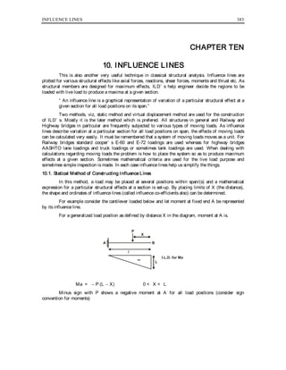
  • 1. INFLUENCE LINES 383 CHAPTER TEN 10. INFLUENCE LINES This is also another very useful technique in classical structural analysis. Influence lines are plotted for various structural effects like axial forces, reactions, shear forces, moments and thrust etc. As structural members are designed for maximum effects, ILD’ s help engineer decide the regions to be loaded with live load to produce a maxima at a given section. “ An influence line is a graphical representation of variation of a particular structural effect at a given section for all load positions on its span.” Two methods, viz, static method and virtual displacement method are used for the construction of ILD’ s. Mostly it is the later method which is prefered. All structures in general and Railway and Highway bridges in particular are frequently subjected to various types of moving loads. As influence lines describe variation at a particular section for all load positions on span, the effects of moving loads can be calculated very easily. It must be remembered that a system of moving loads moves as a unit. For Railway bridges standard cooper’ s E-60 and E-72 loadings are used whereas for highway bridges AASHTO lane loadings and truck loadings or sometimes tank loadings are used. When dealing with calculations regarding moving loads the problem is how to place the system so as to produce maximum effects at a given section. Sometimes mathematical criteria are used for the live load purpose and sometimes simple inspection is made. In each case influence lines help us simplify the things. 10.1. Statical Method of Constructing Influence Lines In this method, a load may be placed at several positions within span/(s) and a mathematical expression for a particular structural effects at a section is set-up. By placing limits of X (the distance), the shape and ordinates of influence lines (called influence co-efficients also) can be determined. For example consider the cantilever loaded below and let moment at fixed end A be represented by its influence line. For a generalized load position as defined by distance X in the diagram, moment at A is. BA P X l L I.L.D. for Ma Ma = − P (L − X) 0 < X < L Minus sign with P shows a negative moment at A for all load positions (consider sign convention for moments)
  • 2. 384 THEORY OF INDETERMINATE STRUCTURES For X = 0 (load at point B) moment at A is − PL. Influence co-efficient is L at B. If X = L load is at A so moment at A is zero. Influence co-efficent is zero. In between A and B, moment at A varies linearly, joining the points, ILD for Ma is obtained. Now even if several loads are placed on the cantilever, Ma is simply the sum of all loads when multiplied by corresponding ordinates. If a cantilever supports a ud.l, the above I.L.D for Ma is applicable. Consider a strip of width dX located at a distance X from free end, w A wdX b L X dX y L - X Ma = b ∫ o WydX = w b ∫ o ydX Where b ∫ o ydX is area of I.L.D between limits zero to b. 10.2. Influence Lines for beam Reactions: ILD’ s for reactions in case of simple beams and compound beams (determinate beams resting over several supports) can be drawn by using the already described procedure. Consider a simple beam with a single load sitting at any moment of time as shown From statics it can be shown that BA P X L Ra = PX L Rb = P(L - X) L (L - X) L yi l I.L.D. for Rb I.L.D. for Ra l yi X/L Ra = PX L and Rb = P    L − X L 0 < X < L
  • 3. INFLUENCE LINES 385 When X = 0 (load at B); Ra = 0 and Rb = P (by putting limits in above expressions) When X = L (load at A); Ra = P and Rb = 0 (by putting limits in above expressions) Instead of maximum co-efficients equal to P it is costomary to have them equal to 1 so that these could be evaluated by the product of loads and respective ordinates and these diagrams become valid for several loads. So algebraically Ra = ∑ Pi yi Rb = ∑ Pi yi 10.3. Principal of Virtual Displacements: Consider a simple beam under the action of load P as shown. Ra can be found by virtual displacements by imagining that support at A has been removed and beam is under the action of load P and Ra. Under the action of Ra, beam is displaced as A/ B. The virtual work equation is BA P X L Ra y A / Ra × AA/ − Py = 0 (Force × displacement) So Ra = Py AA/ where y is the displacement due to Ra under P. If AA/ = 1, Ra = Py A result already obtained. This procedure of drawing ILDs’ is more useful for the complicated cases. 10.4. Reactions for Compound Beams: A beam resting over several supports which has been made determinate by the availability of inserted hinges at suitable points is called a compound beam. The following Rules must be kept in mind while constructing ILD’ s for such cases. 1. Points of I.L.D corresponding to supports should show zero displacement except where virtual displacement is given (in case of reactions). 2. Portion of the beam between hinges which are straight before virtual displacements should remain straight after virtual displacement. 3. If a beam is continuous over two consecutive support and there is a hinge after these two supports, that portion of beam behaves a unit in case the virtual displacement is given elsewhere. 4. Portions of beam between pins which is straight before virtual displacement, shall remain
  • 4. 386 THEORY OF INDETERMINATE STRUCTURES straight after virtual displacement. Considering these guidelines given, draw influence lines for reactions for the following beam. I. L. D for Ra I. L. D for Rb I. L. D for Rc I. L. D for Rd I. L. D for Re I + + I + I + + I + + I A F B G C H D E If positive areas of above diagrams are loaded, upward reactions at corresponding support will occur or vice-versa. Construct Influence lines for reactions for the following compound beam by virtual displacements.
  • 5. INFLUENCE LINES 387 I. L. D for Ra I. L. D for Rb I. L. D for Rc I. L. D for Rd I. L. D for Re I + + I + I + +I + I A G B H C I D E J F + I. L. D for Rf I Evaluation of maximum upward and down reaction due to concentrated loads and udl can be done by using the basic principles described already. If several moving loads, from right to left direction, approach left hand support of a simple beam, the left reaction continues to increase and becomes maximum till leading wheel is at the left support. This corresponding first maxima will decrease immediately if the load falls off and leaves the span from left upon further advance, reaction at left support will start increasing and will become maximum again when second wheel is at the left support. So there will be as many maxima as is the number of loads. Evaluation of reactions due to live load udl is rather simple as the span portion required to be loaded for maximum upward and downward support reactions are obvious by the simple inspection. Of course positive areas if loaded will give maximum upward reactions and vice-versa.
  • 6. 388 THEORY OF INDETERMINATE STRUCTURES 10.5. Influence Lines for Shear Force: In structural analysis, normally we develop the methods by considering simple cases and some generalized conclusions are drawn which can then be applied to more complicated cases. So consider the following simple beam wherein a moving load (right to left) occupies the position shown at any instant of time. Using left-up and write-down as sign convention for positive shear force. A P X B C a b Ra Rb For all load positions to right of point C, the shear force for at C (Vc) is equal to + Ra. Vc = Ra It means that for load position between point B and C, the Shape of ILD for SF at C will be the same as the shape of ILD for + Ra. For all load positions to left of point C, the shear force at C (Vc) is equal to − Rb. Vc = − Rb It means that for load position between point A and C, the shape of ILD for SF at C will the same as shape of ILD for −Rb. Knowing that positive ILD is drawn above the reference line and negative ILD is drawn below the reference line, we obtain the ILD for Vc as shown below with the help of ILD’ s for reactions (+ Ra1 − Rb) A P X B C a b Ra Rb L l b/L a/L + l I. L. D. for + Ra I. L. D. for - Rb I. L. D. for Vc
  • 7. INFLUENCE LINES 389 Mathematically Ra = PX L 0 < X < L Rb = P (L − X) L 0 < X < L At X= 0, load is at B and Vc is zero. At x= b, load is at C and Vc = + Ra = Pb L or b L if P= 1. The ordinates a L and b L can be obtained by using similar triangles. Now inspect the ILD for Vc. For a right to left advance of load system, Vc keeps on increasing till the “ leading load is at the section” , when leading load just crosses the section, Vc drops by the magnitude of load and this process continues. So we can write that for maximum SF at a section, “ the load should be at that section” . This is the first criterion of calculation of Vmax. Now the question comes to mind that which load among the moving load system should be placed at the section? To address this question, we have noted, that change in SF at a section, ∆V, is equal to change in Ra (∆Ra) minus the load leaving the Section. (Pn) So, ∆V = ∆Ra − Pn If W is sum of all the loads on the span L before advance of a, it can be shown that ∆Ra = Wa L So, ∆V = Wa L − Pn Any load which reverses this expression, should be brought back and placed at that section to realize the maximum SF at that section. So a change in the sign of above expression can be regarded as the second criterion for maximum shear force at a section. It can also be shown that loads entering or leaving the span as a result of any particular advance do not affect the above expression very significantly. The above method is called the statical method. The same shape of ILD for Vc can be obtained by virtual displacement method also. A B C a b Ra RbL b/L a/L + I. L. D. for Vc V V
  • 8. 390 THEORY OF INDETERMINATE STRUCTURES Now imagine that resistance to vertical displacement at C has been destroyed (imagine a sort of cut at the section) and the vertical shear force as shown (opposite to sign convention for positive shear force). The area enclosed between the original position before virtual displacement and the deformed position after virtual displacement is the ILD for Vc. 10.6. Influence Line Diagrams for Bending Moment: Again we consider the simple beam under the action of a simple moving load as shown. Let it be required to construct ILD for Mc. A P X B C a b Ra Rb L I. L. D. for Mc ab/L ILD for Ra x a ILD for Rb x b + a b If the load is between points B and C. Mc = Ra × a = PX L × a 0 < X < b at X = 0; load at B, Mc = 0. If X = b; Mc = Pab L    = ab L if P = 1 It means that for portion BC, the shape of ILD for Mc is the same as the shape of ILD for Ra multiplied by distance a. If the load is between points A and C Mc = Rb × b = P(L − X) L × b b < X < L At X = b, load is at C; , Mc = Rb × b So Mc = Pab L    = ab L if P = 1
  • 9. INFLUENCE LINES 391 It means that for portion AC, the shape of ILD for Mc is the same as the shape of ILD for Rb multiplied by b. At X = L; Load at A; Mc = 0 The same shape of ILD for Mc can be obtained by virtual displacements also. A P X B C a b I. L. D. for Mcy M M a b Ra Rb dx M M Idealized section at C before virtual displacements Section at C after virtual displacement The virtual work equation is work done by loads = work done by the moments. P × y = M × δθ. Or M = Py δθ So, if δθ = 1; the moment at Section C for a single load system will be load multiplied by corresponding influence ordinate (influence co-efficient) while constructing ILD’ s by virtual displacements, loads are not considered. Now construct ILD for Mc by virtual displacements. At Section C, we imagine that the beam resistance to moments which produce rotations has been destroyed while resistance to shear and axial loads is intact. This situation is obtained by considering that at Section C; there is a sort of hinge (one degree of freedom system). On this hinge the moments are
  • 10. 392 THEORY OF INDETERMINATE STRUCTURES applied on two sides of hinge as shown alone. The segments of beam rotate and the displaced beam position is ILD for Mc. The one-degree of freedom system such as a hinge is further explained in diagrams shown which illustrate the movement. This procedure can now be applied to more complicated cases where statical approach may be laborious. The method of virtual displacements can be applied to more complicated cases like compound beams etc., by considering the basic ideas established in this chapter. A + ++ + E B C F D 1 2 3 1 2 3 ILD for M1 - 1 ILD for M2 - 2 ILD for M3 - 3 10.7. Evaluation of Mmax at a Section In case of a simple beam supporting a moving load system, the maximum moment at a section is obtained when 1. One of the loads is at the section. 2. In case of several moving loads, that load shall be placed at the Section, for producing maximum moment at that Section, which reverses the average loading on two portions of span adjacent to Section.
  • 11. INFLUENCE LINES 393 Average loading on any portion = sum of all loads on that portion length of portion 10.8. Absolute Maximum bending Moment In case of a series of moving loads traverse on a beam, the absolute maximum bending moment occurs near the mid span under the adjusted position of that load which gave us maximum bending moment at mid span. Procedure is as follows: 1. Apply the criteria of maximum bending moment at mind span to find the load which is to be placed at mid span. 2. For this position of loads find the position of resultant of all loads on span. 3. Move the system slightly so that mid-span is bisected by the resultant of all loads on span and the load which gives us maximum bending moment at mid-span. 4. Find absolute maximum bending moment. It will occur under displaced position of that load which gave us maximum bending moment at mid-span. Considering that invariably loads would be magnified for design purpose and appreciating that the numerical difference between the values of maximum mid-span bending moment and absolute maximum bending moment is insignificant, evaluation of absolute maximum bending moment for a given moving load system appears to be of theoretical interest only. How interested students can evaluate it for only moving load system by considering the above four points and guidelines contained in this chapter. 10.9. Girders with Floor beams (Panelled girders) Normally in bridge construction, moving loads are hardly applied to the main girders directly but instead following arrangement is used for the load transfer. The moving load system comes on the stringers which transfer it to the main girder through floor beams in form of concentrated loads (Reactions of floor beams). So main girder is subjected to concentrated loads only. For large spans the main girder may be of steel, poured in-situ reinforced concrete or pre-stressed concrete. Points a, b, c, …. F are called panel points and the distance between any two panel points is called a panel. With the above mentioned load-transfer mechanisms, it can be easily seen that ILD’ s for main reactions remain same as that for a simple beam as discussed already.
  • 12. 394 THEORY OF INDETERMINATE STRUCTURES As there will be no load on the main girder except floor beam reactions, it is stated that for a given load position, the shear force within a panel remains constant so we can talk of shear force in panels rather that shear force at a section (panel and becomes a section). Let us now construct ILD’ s for shear force for various panels of girder already shown.
  • 13. INFLUENCE LINES 395 4/5 ILD for + Ra ILD for Vab ILD for Vef ( + ) ( - ) ILD for + Ra ILD for - Rb ( - ) ( + ) 0.4 0.4 ILD for Vcd ILD for - Rb ILD for Rb x b ILD for Ra x a 3a/5 b/5 yb yc+ a b ILD for Mmn d x 4d 5d 6 d 5 2d x 3d 5d = + ILD for Mc I I A five panels main girder is shown for which various ILD’ s have been sketched.
  • 14. 396 THEORY OF INDETERMINATE STRUCTURES 10.10. ILD For Vab (ILD for shear in end panel) If a load P is placed at a distance X from panel point b, then reactions at panel points a and b will be PX d and P(d − X) d respectively. Pa = Panel point load at a or reaction of floor beam at a = Px d , 0 < X < d Pb = Panel poiint load at b or reaction of floor beam at b = P(d − X) d 0 < X < d. if X = 0, load P will be at b, then Pa = 0 and Pb = P if X = d, load P will be at a, then Pa = P and Pb = 0 So, Vab ≡ 0 In between a and b, shear force varies linearly. Now inspect the shape of ILD for Vab, it resembles with the shape of ILD for moment at point b considering the panelled girder as a simple beam. So to evaluate (Vab)max, criteria of max bending moment at a section b (reversal of average loading expression) will be applied. 10.11. ILD for Vef (ILD for shear in other end panel) The construction of ILD for Vef is same as that for Vab and same arguments apply. Inspecting this diagram, it is clear that the shape resembles with ILD for bending moment at e if panelled girder was treated as a simple beam. So to evaluate (Vef)max, the criteria for maximum bending at point e shall be applied. 10.12. ILD for Ved (ILD for shear in intermediate panel) Considering the load P on panel cd acting at a distance X from panel point d. Pd = Panel point load at d or floor-beam reaction at d = P(d − X) d , 0 < X < d. Pc = Panel point load at c or floor-beam reaction at c = P(X) d , 0 < X < d. If load is to right of d; Vcd = + Ra So, ILD for Vcd for this region will be the same as that for Ra. If load is to left of C, Vcd = − Rb. So for this region shape of ILD for Vcd will be the same as the shape of ILD for − Rb. Now third possibility is load actinig on span CD itself as shown. Inspecting the expressions for panel point loads at d and c stated above, we observe that the shear Vcd within the panel varies linearly. So joining the ordinates under points C and D by a straight line will complete ILD for Vcd. 10.13. Evaluation of (Vcd)max (Maximum shear force in intermediate panel) If a moving load is advanced at point d in a direction from right to left, considering W/ is resultant of all loads on span CD, the following criteria can be easily developed as a consequence of variation of shear force is panel CD due to an advance. W L > W/ d Any load which reverses the above criteria shall give (Vcd)max.
  • 15. INFLUENCE LINES 397 10.14. ILD for Mmn Section mn is located within panel bc. Same technique can be applied for constructing ILD for Mmn. If load P is to right of panel point C. Mmn = Ra × a. It means that if load is between points c and f, the shape of ILD for Mmn will be the same as shape of ILD for Ra multiplied by a. If load P is to left of panel point b, then. Mmn = Rb × b. It means that if load is between points a and b, then shape of ILD for Mmn will be the same as shape of ILD for Rb multiplied by b. Now consider load within panel bc with P acting at a distance X from c. Pb = PX d and Pc = P(d − X) d 0 < X < d. then Mmn = Pb yb + Pc yc = PX d yb + P(d − X) d yc 0 < X < d. So between the panel, the moment varies linearly. Therefore joing the ordinates of ILD for Mmn at b and c by a straight line, we complete the ILD for Mmn. Now it is understood that SF is generally maximum near the support while moment is generally maximum near the mid-span. So ILD for Mmn can also be used to evaluate corresponding maxima. If criteria of maximum bending moment is applied at a section corresponding to bigger ordinate, then (Mmn)max can be calculated for a moving load system. 10.15. ILD for Mc At the panel points, the load is directly transmitted to the main girder and the panel girder behaves as a simple beam at the panel points. So ILD for Mc will be drawn considering the girder as a simple beam. 10.16. Influence Lines for axial forces in Truss Members: As before, let us consider a simple case of parallel chord truss carrying loads at its lower chord. The conclusions obtained are general and can be extended to non-parallel chord trusses.
  • 16. 398 THEORY OF INDETERMINATE STRUCTURES 1 2 3 4 A G C F E D B h ( - ) ( + ) ( + ) ( - ) ( + ) I θ θ ILD for S1 When a moving load system traverses the bottom chord of this trussed bridge, it is known that forces in top chord members will be compressive in nature while that in bottom chord will be tensile in nature. The forces in chord members are a function of moment divided by truss height. For a chord member take “ moment at the point where other two members completing the same triangle meet divided by height of truss.” This has already been established in this book when discussing method of moments and shears. So applying this S1 is a compressive force, so assigned a negative sign, equal to moment at C divided by the height of truss. So considering the truss as a simple beam, draw an ILD for Mc and divide it by the height of Truss. (S1)max can be evalutated by applying the criteria of maximum bending moment (Average loadings) at point C considering the truss as a simple beam.
  • 17. INFLUENCE LINES 399 ILD for S3 It is a tensile force equal to moment at D divided by height of Truss. (S3)max can be evalauted by applying the criteria of maximum bending moment at point D. ILD for S2 It is known that axial force in an inclined member is ± V ± Cosθ . Minus before Cosθ shall be taken if the angle “ between inclined member and vertical” is counterclockwise. Now if the load is right of D, SF applicable to member 2 is + Ra. So corresponding portion of ILD for + Ra is taken. This is divided by − Cosθ. If the load is to left of C, SF applicable to member 2 is − Rb. So corresponding portion of ILD for − Rb is taken. This is again divided by − Cosθ. In between the panel SF varies linearly so we can join the corresponding points. The shape of ILD for S2 resembles with the shape of ILD for intermediate panel shear in a panelled girder. So (S2)max can be evaluated by applying the criteria of maximum intermediate panel shear. ILD for S4 If the load is at E or right of E, Force in member 4 is zero and if load is at or to left of point C, again the force in member 4 is zero. If the load is at F, the same will be the tensile force in member. Using these boundary conditions, ILD for S4 is constructed. Now inspect its shape. It resembles with the shape of ILD for moment at F (or D) in an equivalent simple beam of span CE. So (S4)max can be evaluated by applying the criteria of maximum bending moment (average loading criteria) at F (or D). 10.17. Influence lines for moment and horizontal thrust in a three hinged arch. We know that H = µc yc and Mx = µx − Hy. Where y will be the rise of arch at a distance X from origin (usually a support).
  • 18. 400 THEORY OF INDETERMINATE STRUCTURES y yc x C A H B H L Va Vb x(L - x) L Ly 4yc L 4yc ( + ) ( + ) ( - ) ILD for H ILD for Mx ( + ) Shaded area Influence line for any structural effect can be drawn by following the formula for that structural effect. 10.17.1. ILD for horizontal thrust H Horizontal thrust H is developed at the springings (supports) of an arch. Examine the formula for H    H = µc yc . So ILD for H will be obtained if ILD for moment at centre is drawn, considering the arch to be a simple bam, and is then divided by yc. The peak ordinate of ILD for H will be L µyc . (H)max due to a moving load system can be obtained by applynig the criteria of maximum bending moment at the centre. 10.17.2. ILD for Moment in the arch From the Eddy’ s theorem we know that bending moment in the arch at a distance x from support is Mx = µx − Hy where µx = simple span bending moment at a distance X.
  • 19. INFLUENCE LINES 401 So as a first step, we construct ILD for simple span bending moment at a distance X. Then we subtract the ILD for Hy. The net area between these two diagrams is the ILD for moment in the arch as shown. 10.18. Standard Leadings For the design of Railway bridges standard Cooper’ s E-60 and E-72 loadings consisting of two locomotives each weighing 213 tons on 18 axles each followed by infinite udl representing compartments is considered. Structural affects obtained for a E loading can be used to get the same for another E loading by simply multiplying them with the ratio of E loadings. Original E-60 or E-72 loadings are in kip-ft. system as follows: 15 ↓ 8/ 30 ↓ 5/ 30 ↓ 5/ 30 ↓ 5/ 30 ↓ 9/ 4 of 19.5 ↓ 5 ↓ 6 ↓ 5 ↓ 8/ 15 ↓ 8/ 4 of 30 ↓ 5/ ↓ 5/ ↓ 5/ ↓ 9/ 4 of 19.5 ↓ 5/ ↓ 6/ ↓ 5/ ↓ 5/ 3/ft Above wheel loads are in kips per rail or tonnes per track. (1 Ton = 2 Kips ; small ton) Converting E-72 loading in SI Units we have IK = 5 KN approximately. 80 KN ↓ 2.44 4 of 160 KN ↓ 1.52 ↓ 1.52 ↓ 1.52 ↓ 1.52 ↓ 2.74 4 of 104 KN ↓ 1.52 ↓ 1.83 ↓ 1.52 ↓ 2.44 80 ↓ 2.44 4 of 104 KN ↓ 1.52 ↓ 1.52 ↓ 1.52 ↓ 2.42 4 of 104 KN ↓ 1.52 ↓ 1.83 ↓ 1.52 ↓ 1.52 53 KN/m Cooper’ s E-72 loading in SI-units is shown above and E-60 below: 66.75 ↓ 2.44 4 of 133.5 KN ↓ 1.52 ↓ 1.52 ↓ 1.52 ↓ 2.74 4 of 86.77 KN ↓ 1.52 ↓ 1.83 ↓ 1.52 ↓ 2.44 66.75 ↓ 2.44 4 of 133.5 KN ↓ 1.52 ↓ 1.52 ↓ 1.52 ↓ 2.74 4 of 86.77 KN ↓ 1.52 ↓ 1.83 ↓ 1.52 ↓ 1.52 43.8 KN/m Distance between loads is in meters. For highway bridges AASHTO HS24-44 loading is internationally considered and it consists of a Tractor and Semi-trailer with three axles carrying 0.2W, 0.4W and 0.4W respectively. These loads when converted into kips are 16k, 32k and 32k. Standard AASHTO lane loading is probably 100 lbs/ft2 . However, in our country, due to circumstances 70 ton tank loading or Truck-train loading described in Pakistan Highway code can be used. We shall use railway loadings only. Let us solve some typical problems now. Example No.1: In a girder with Floor beams having five equal panels of length 9 meters each. Determine (a) Maximum positive and negative end panel shears. (b) Maximum Shear in the first intermediate panel from left hand end. The live load is Coopers E-72 loading.
  • 20. 402 THEORY OF INDETERMINATE STRUCTURES ( + ) ( - ) ( - ) ( + ) ILD for Vab ILD for Vef ILD for Vbc 0.80 0.6 0.2 0.80 SOLUTION: 1. Maximum positive End Panel Shears (Vab)max Advance loads at section B and use criteria W/ d < W L Portion ab Portion bf 80 9 < 2498.87 45 after 1st advance. 240 9 < 2338.87 45 after 2nd advance 400 9 < 2178.87 45 after 3rd advance 560 9 > 2018.87 45 after 4th advance. It means that once 3rd load of 160 KN crosses point b, the criterion is reversed so for maximum end panel shear, 3rd load of 160 KN should be placed at point b. Now place the system of loads accordingly and compute corresponding ordinates.
  • 21. INFLUENCE LINES 403 3.52 2.44 1.52 1.52 1.52 2.74 1.52 1.83 1.52 2.44 2.44 1.52 1.52 1.52 2.44 1.52 1.83 1.52 1.52 1 2 3 4 5 6 7 8 9 10 11 12 13 14 15 16 17 18 19 8.6 m 4 of 160 4 of 104 4 of 160 4 of 104 8080 y1 y4 y19 0.8 ILD for Vab Ordinates Under Loads: y1 = 0.3128 y2 = 0.5297 y3 = 0.6648 y4 = 0.80 y5 = 0.766 y6 = 0.7053 y7 = 0.6715 y8 = 0.6308 y9 = 0.597 y10 = 0.5428 y11 = 0.488 y12 = 0.4548 y13 = 0.421 y14 = 0.387 y15 = 0.333 y16 = 0.299 y17 = 0.2586 y18 = 0.2248 y19 = 0.191 (Vab)max = 80 × 0.3128 + 160 (0.5297 + 0.6648 + 0.8 + 0.766) + 104 (0.7053 + 0.6715 + 0.6308 + 0.597) + 80 × 0.5428 + 160 (0.488 + 0.4548 + 0.421 + 0.387) + 104 (0.333 + 0.299 + 0.2586 + 0.2248) + 1 2 × 8.6 × 0.191 × 53 = 25.024 + 441.68 + 271.62 + 43.42 + 280.128 + 116 + 43.52 = 1221.4 KN. Similarly (Vef)max = -1145 KN (Do the Process yourself) We have to observe a similar Process for evaluation of (Vef)max as was used for (Vab)max. The loads will be advanced at point e and average loadings on portions ae and ef will be compared. The
  • 22. 404 THEORY OF INDETERMINATE STRUCTURES load which produces reversal after advance should be brought back and placed at section e for (Vef)max. Evaluation of (Vbc)max 1 2 3 4 5 6 7 8 9 10 11 12 13 14 15 16 17 18 4 of 160 4 of 104 4 of 160 4 of 104 8080KN y1 y4 y18 0.6 0.82m f y14 e d y5 + c ba ILD for Vbc ( )- 0.2 2.25 6.75m I.L.D for Vbc Once loads are advanced from right to left at C, the following criteria shall be used to evaluate maximum intermediate panel shear (Vbc)max W L > W/ d Portion bc portion cf 80 9 < 2064 45 after 1st advance. 240 9 < 2168 45 after 2nd advance 400 9 < 2272 45 after 3rd advance 560 9 > 2315.46 45 after 4th advance. So maximum positive SF in panel bc will be obtained when 3rd wheel of 160 KN is placed at point c. Now place loads as shown above and determine corresponding ordinates of ILD. Multiply loads and ordinates by giving due care to signs of ILD, we obtain (Vbc)max. Now from similar triangles, influence co-efficients y1,...... y18 are: y1 = 0.113 y2 = 0.33 y3 = 0.465 y4 = 0.6 y5 = 0.566 y6 = 0.505 y7 = 0.472 y8 = 0.431 y9 = 0.397 y10 = 0.343 y11 = 0.289 y12 = 0.255 y13 = 0.221 y14 = 0.187 y15 = 0.126
  • 23. INFLUENCE LINES 405 y16 = 0.093 y17 = 0.052 y18 = 0.018 So, (Vbc)max = 80 × 0.113 + 160 (0.33 + 465 + 0.6 + 0.566) + 104 (0.505 + 0.472 + 0.431 + 0.397) + 80 × 0.343 + 160 (0.289 + 0.255 + 0.221 + 0.187) + 104 (0.126 + 0.093 + 0.052 + 0.018) (Vbc)max = 720.34 KN EXAMPLE NO.2: Determine the maximum bending moment at a cross-section 9.1m from left hand for a beam of span 27.3m. The moving live load is 117 KN/m having a length of 6m. SOLUTION: Sketch ILD for moment at the indicated section. Now let us assume that the given position of Udl gives us(Mc)max at a distance X from C as shown. Determine Ra for this position ∑Mb = 0 Ra × 27.3 = 702 (3 + 12.2 + X)
  • 24. 406 THEORY OF INDETERMINATE STRUCTURES Ra = 390.84 + 25.71 X Moment at C = Mc = Ra × 9.1 − 117 X2 2 Mc = (390.84 + 25.71) 9.1 − 117 X2 2 Simplify Mc = 3556.64 + 233.96 X − 58.5 X2 If BM at C is maximum, then d Mc dX = Vc = 0 233.96 X − 2 × 58.5 X = 0 X = 2m Now compute y1 and y2 from similar triangles of ILD 18.2 27.3 = y1 7.1 → y1 = 4.733 m 9.1 27.3 = y2 14.2 → y2 = 4.733 m So (Mc)max = ud.l × area of ILD Under UDL = 117 (6 × 4.733 + 1 2 × 6 × 1.327) = 3788.3 KN-m
  • 25. INFLUENCE LINES 407 EXAMPLE NO. 3: Calculate maximum bending moment at Section mn and pq of a five panel bridge. Each panel is of 9m. Five loads of 160 KN each spaced at 1.52m travel from right to left. 1.52 1.52 1,521.52 160 160 160 160 160 8.1 6.3 y2 y1 y4 y3 5 of 160 ILD for Mmn ILD for Mpq 99 Evaluation of (Mmn)max It is recommended that criteria of maximum bending moment be applied at maximum ordinate of 8.1 corresponding to Panel point C. Now comparing average loadings on portion ac and cf, we find that 3rd load reverses the criterion as it crosses. So it must be placed at point C. Determine ordinates
  • 26. 408 THEORY OF INDETERMINATE STRUCTURES 8.1 27 = y3 25.48 → y3 = 7.644, y4 = 7.188, y1 = 6.3 + 1.496 = 7.796 y2 = 6.3 + 1.192 = 7.492 (Mmn)max = 160 (7.492 + 7.796 + 8.1 + 7.644 + 7.188) = 38.22 × 160 = 6115.2 KN-m The reader is also suggested to calculate (Mmn)max. by coinciding the resultant of moving load system with the maximum ordinate. Place the loads accordingly. Compute influence co-efficients and multiply loads with respective ordinates to compute (Mmn)max. Compare this value with the previous one. (Mpq)max As ILD for Mpq is symmetrical about centre-line (mid span), Arrange the loads such that the resultant falls on mid-span. All five loads shall be accommodated and will have an ordinate of 9. (Mpq)max = 160 (9 + 9 + 9 + 9 + 9) = 7200 KN-m Important: The instructor is advised to work with lesser number of loads, usually five to seven, in the class and Establish the procedure. The students can then be given assignments involvinig standard trains etc., for clarification of their concepts. EXAMPLE NO. 4: A simple beam has a clear span of 27.5 m. Construct ILD for SF at a section 6.1m from left support. How should Coopers-E-60 loading be placed to calculate maximum shear force at this section? SOLUTION: Draw ILD for Vc. Advance the loads at section C. We shall show the load position required for (Vc)max only. ( - ) ( + ) 66.75 4 of 133.5 4 of 86.77 3 of 133.5 66.75 1.28 m CA B 6.1 m 21.4 m 0.778 y1 y2 y9 y12 ILD for Vc 0.222 Computing influence co-efficients y1......y12 from similar triangles.
  • 27. INFLUENCE LINES 409 y1 = − 0.133, y2 = 0.722, y3 = 0.667, y4 = 0.612, y5 = 0.512 y6 = 0.4566, y7 = 0.3901, y8 = 0.335, y9 = 0.246, y10 = 0.157 y11 = 0.10, y12 = 0.0466 In order to have (Vc)max, at least one load should be at C. To decide which load should be placed at C, reversal in the sign of following equation is sought. ∆V = Wa L − Pn W = Sum of all the loads on span before advance. a = any particular Advance L = Span Pn = magnitude of Load crossing the section due to an advance. ____ For the first advance ∆V = 1281.58 × 2.44 27.5 − 66.75 = + 46.96 KN. It shows that SF at C has increased due to 1st advance. ____ For second advance. ∆V = 1415 × 1.524 27.5 − 133.5 = − 55.08 KN. It shows that if second advance at C is made, Vc decreases. So for (Vc)max, position before 2nd advance (after 1st advance) is required. For this position above influence co-efficients have been computed. (Vc)max = 66.75 (− 0.133) + 133.5 (0.778 + 0.722 + 0.667 + 0.612) + 86.77 (0.512 + 0.4566 + 0.3901 + 0.335) + 66.75 (0.246) + 133.5 (0.157 + 0.1 + 0.046) = 567.37 KN EXAMPLE NO. 5:- Calculate the maximum bending moment at the points C and D if five loads of
  • 28. 410 THEORY OF INDETERMINATE STRUCTURES 160 KN each spaced at 1.52 m cross-the bean from right to left. CA B 7 m 7 m 14 m 5.25 y1 y2 y3 y4 y5 (+) 1.521.521.521.521.52 5 of 160 KN y1 y2 y3 y4 y5 (+) ILD for Mc ILD for Md D MCMax Line-up all loads upto point C (theoretically slightly to right of C). Give advances at point C and compare average loading in portion AC and BC due to various advances. Portion Ac Portion Bc 160 7 < 4 × 160 21 after 1st advance. 2 × 160 7 > 3 × 160 21 after 2nd advance. So, as the second load of 160 KN crosses ponit C, reversal is obtained. So for (Mc)max, this load
  • 29. INFLUENCE LINES 411 should be brought back and placed at C (position before 2nd advance or after 1st advance). Compute influence co-efficients. y1 = 4.11, y2 = 5.25, y3 = 4.87 y4 = 4.49, y5 = 4.11 (Mc)max = 160 (4.11 + 5.25 + 4.87 + 4.49 + 4.11) = 3652.8 KN-m (Md)max This section is mid span of beam. Clearly applying the criteria of maximum bending moment at D (comparing Average loadings on AB and BD), we get Span AD Span BD 160 14 < 4 × 160 14 after 1st advance 2 × 160 14 < 3 × 160 14 after 2nd advance 3 × 160 14 > 2 × 160 14 after 3rd advance. So position before 3rd advance (or after 2nd advance) will give us (Md)max. Place the loads accordingly and compute influence co-efficients. y1 = y5 = 5.48 y2 = y4 = 6.24 y3 = 7 So, (Md)max = 160 (5.48 + 6.24 + 7 + 6.24 + 5.48) = 4870.4 KN-m EXAMPLE NO.6: Calculate maximum axial forces induced in members 1, 2, 3 and 4 of truss already shown if five loads of 150 KN each spaced at 1.52m corsses at the bottom chord from right to left. Take h = 2m and span = 5d = 10 meters.
  • 30. 412 THEORY OF INDETERMINATE STRUCTURES SOLUTION: The corresponding ILD’ s for S1.....S4 have already been plotted. Now we will use those diagrams to calculate maxima. See the Truss of article 9.16. 160 ( + ) ( + ) ( - ) 1.521.521.521.52 5 of 160 KN 1.521.521.521.52 5 of 160 KN 1 m 1 m +0.565 ( + ) 1.52 1.53 y1 y3
  • 31. INFLUENCE LINES 413 S1max. The shape of ILD for S1 resembles with the shape of ILD for Mc in an equivalent simple beam. So giving advances at C (now forget the truss and play with ILD’ s only). Apply the criterion for maximum moment at C. Portion Ac Portion Bc 160 4 < 4 × 160 6 after 1st advance. 2 × 160 4 = 3 × 160 6 after 2nd advance. Considering equality as a reversal, S1max will be obtained for position before second advance (or after 1st advance). Place loads accordingly and compute influence co-efficients. y1 = .744, y2 = 1.2 y3 = 0.896 y4 = 0.592 y5 = 0.288 So, S1max = 160 (0.744 + 1.2 + 0.896 + 0.592 + 0.288) = − 595.2 KN (It is a compressive force) S3max Inspect the shape of ILD for S3. It resembles with the shape of ILD for moment at D considering the truss to be a simple beam. So apply the criterion of maximum moment at D. Portion AD Portion BD 160 6 < 3 × 160 4 (last load not on span) after 1st advance. 2 × 160 6 < 3 × 160 4 After 2nd advance. 3 × 160 6 = 2 × 160 4 After 3rd Advance. So for S3max, position before 3rd advance is valid (After second advance). Place the loads accordingly and compute influence co-efficients. y1 = 0.592, y2 = 0.893, y3 = 1.2, y4 = 0.744, y5 = 0.288 (S3)max = 160 (0.592 + 0.893 + 1.2 + 0.744 + 0.288) = 594.72 KN (It is a tensile force). S2max Inspect the shape of ILD for S2. It resembles with the shape of ILD for as shear force in a intermediate panel of a panelled girder. So for evaluating S2max, we apply the criterion of maximum intermediate panel shear. Advance is made at D or F. W/ d < W L 160 2 = 5 × 160 10 after 1st advance. So for S2max, the leading load should be placed at maximum ordinate, only three loads will be
  • 32. 414 THEORY OF INDETERMINATE STRUCTURES acting on portion BD. y1 = − 0.565 y2 = − 0.3503 y3 = − 0.1356 (S2)max = 160 (− 0.565 − 0.3503 − 0.1356) = − 168.144 KN (It is a compressive force) S1max y1 = y3 = 0.24 y1 = 1 S1max = 160 (0.24 + 1 + 0.24) = 236.8 KN (It is a tensile force) 10.19. Influence Lines for Statically Indeterminate Structures: The same procedure can be adopted for constructing ILDs’ for indeterminate structures. However, compatibility and redundants have to be considered as demonstrated earlier. INFLUENCE LINE DIAGRAM FOR INDETERMINATE BEAMS(By method of virtual displacement) Influence line diagram for Shear. In virtual work for shear the B.M. does not do any work only shear force does the work. Case 1: Let us investigate ILD at a section of a simple beam. The section is at a distance a from A and at b from B support. This has already been done.
  • 33. INFLUENCE LINES 415 P = 1.0 a v c c A B b C // C/ Ra Rb c b 2* 2* 1* 1* * = 1/L a RBRA * = 1/L C / b/L a/L y C// c This is ordinate of ILD under load A By Virtual Work: Both the lines are parallel therefore, its work done by Moment is equal to zero. θ* 1 = θ* 2 = θ Va θ* + Vb θ* Virtual Work: (Virtual displacement) (i) total displacement equal to 1 unit. aθ* + bθ* = 1 (ii) total B.M. equal to zero. V(aθ* + bθ* ) − Mθ* + Mθ* − Py* = 0 put aθ + bθ = 1 V(1* ) − Py* = 0 If we take P = 1 V = y* Or θ = 1 L Case 2: I.L.D for bending moment at the same section. Write work equation and equate to zero. Mθ* 1 + Mθ* 2 − Va θ* 1 + Vb θ* 2 − Py* = 0
  • 34. 416 THEORY OF INDETERMINATE STRUCTURES or M (θ* 1 + θ* 2) − 0 − Py* = 0 M (θ* ) = Py* or M = Py θ . If P = 1 and θ = 1 radian. than M = y* So aθ* 1 = bθ* 2 Or θ* 1 + θ* 2 = 1 ⇒ θ* 1 + a b θ* 1 = 1 ⇒ θ* 1 = b L θ* 2 = a L P = 1 V MRA RB b a 2* = a/L * = 1 radC// C / C C y w yw 1* = b/L A B 1* = b 2*a L b a c a/Lb/L RA RB We have obtained ILD for B.M at X in a simple beam Let us now consider the shown conjugate beam.
  • 35. INFLUENCE LINES 417 2m 4m 1.0 = P A C D B Ra RbRc 6m6m 4m 6m 0.6 0/10 0/10 0/10 0.4 2/40 B D 2/10 C Applying same concepts we get following ILD
  • 36. 418 THEORY OF INDETERMINATE STRUCTURES X (L - X) P = 1 A B MB RBRA P aL Consider a propped cantilever If support at A is removed, this will be deflected shape. L-x B.M.D due to load on BDS as cantilever supported at B. 1/3 (L - x) Applying moment area thereon, deflection at part A due to loads is ∆XL = 1 EI    P 2 (l − X)2    l − 1 3 (l − X) (+) L fXX Ra = 1 (deflected shape) of BDS Now consider load under redundant Ra = 1 B.M.D. for Ra = 1 L/3 L /2 2 Applying moment area thereon, deflection at A due to Ra = 1 fXX = 1 EI    1 2 (l)2    2l 3 = l 3 3EI Equation for compatibility ∆al − fXX Ra = 0 because A is a support. Net deflection should be zero.
  • 37. INFLUENCE LINES 419 Ra = Sal fxx , Ra = P(l − X)2 (2l + X) 2l 3 after putting values of Sal and fxx Rb = 1 − Ra (equilibrium requirement) So we get Rb = X(3l 2 − X2 ) 2l 3 We know Mb = Ra × L − P (l − x) . Put value of Ra and simplify Mb = PX(l 2 − X2 ) 2l 2 This expression will help in plotted ILD for Mb ILD for Ra X (L - X) P = 1 A B Mb RbRa 10m Ra = P(l − X)2 (2l + X) 2 l 3 When X = 0 ⇒ Ra = 1.0 (put in above equation for Ra) When X = 5 ⇒ Ra = 5 16 (put in above equation for Ra) 5/16 3rd-degree curve1.0ILD for Ra O Simplify ILD for Rb can be plotted as below: Rb 1.0 ILD for Rb Putting boundary conditions in the Mb expression ILD for Mb is obtained.
  • 38. 420 THEORY OF INDETERMINATE STRUCTURES Mb = PX ( - X ) 2 l l 2 2 2 3/16 l ILD for Mb Ral − P(l − X) + Mb = 0 Mb = 1(l − X) − Ral 10.20. ILD for shear at Section mn: X P A B Mb RbRa 10m b = 6ma = 4m m n m A B Mb RbRa m n c 1.0 ( + ) 1.0 1.0 Vmn I.L.D. for Ra x a I.L.D. for Ra x b Load to right of mn, Vmn = Ra x a it mean ILD for Vmn will be same as ILD for Ra multiplied by a for this portion Load on left of mn Vmn = Rb x b for this portion, ILD for Vmn is same is ILD for Rb x b 10.21. ILD for Mmn Consider a hinge where ILD for moment desired. P = 1 A C 10m B 6m
  • 39. INFLUENCE LINES 421 X P = 1 A C RcRa L1 X P = 1 State-I X 1.0 L2 B Rb Rb B Rb = 1.0 State-II y P ba y X B C C // B // Ra l Rb l Pab l ( )PbX l Primary structure or BDS under load P = 1 and redundant Rb at B. Rb δbb − Py = 0 P = 1 Rb = y δbb Compatibility equation at point B. δbb We know this is ILD for moment at B in a simple beam.
  • 40. 422 THEORY OF INDETERMINATE STRUCTURES y = PbX 6EIl (l2 − b2 − X2 ) (X = 0 − a) y = PaX 6EIl (l2 − a2 − X2 ) (X = 0 − b) y = l2X(l2 − l2 2 − X2 ) 6EIl δbb = l2X (l2 − l2 2 − l1 2 ) 6EIl δbb = l1 2 l2 2 3EIl and    Rb = X (l2 − l1 2 − X2 ) 2l1 2 l2 X = 0 − l1 with Origin at A Rb = X (l2 − l1 2 − X2 ) (2l1 2 l2 2 ) X = 0 to l2 Origin at C
  • 41. INFLUENCE LINES 423 Now assume same values of spans and re-calculate. P = 1 A C L1 = 10m L2 = 6m B P = 1 A C B I.L.D for Rb 1.0 y A C B ( + ) 1.0 1.0 1.0 1.0 B l2 l Ra δaa − Py = 0 Ra =    y δaa I.L.D. for Ra We know l + l = L1 2 Compatibility at A + Rb = X (l2 − l2 2 − X2 ) (2 × l1 2 × l2) = X (162 − 62 − X2 ) 2 × 102 × 6 by putting values of L1l1 and l2
  • 42. 424 THEORY OF INDETERMINATE STRUCTURES X Rb Ra Rc 0 0 1 0.1825 2 0.36 3 0.5275 4 0.68 5 0.8125 6 0.92 7 0.997 Calculate Calculate 8 1.04 yourself yourself 9 10 0 Calculate 1 yourself 2 3 4 ILD for Ra can be obtained from ILD for Rb. Taking moments about C is equality to zero. Ral + Rb × l2 − P(l − X) = 0 So Ra = P    l − X l − Rb l2 l and Rb = (l1 − X) 2l1 2 l (2l1 l − l1 X − X2 )
  • 43. INFLUENCE LINES 425 P = 1.0 A B Mb RbRa X Ma (L - X) P A B MbMa RbRa State-I y B State-IIA 1.0 θaa 1.0 2EI l 4EI l θa = 0 4EI l 2EI l (-) (+) 1 rad 1 rad At fixed support, BDS under redundant moment.