SlideShare a Scribd company logo
1 of 8
Interlocking Principles
Compiled by: BP Johnson
Date: 28 August 2015
Introduction
Many operators experience unintended operating conditions. This document provides some insight into
the various interlocking, inter-tripping, protection and control philosophies, and how these should be
integrated with one another to prevent unintended operations.
Interlocking philosophy
Integral Interlocks
For indoor switchgear the basic integral interlocking principle is shown in figure 1.
In this figure the switchgear circuit (incomer or feeder circuit) is shown in two positions namely:-
a) circuit isolated and earthed and
b) circuit in service, with earth disconnected.
a) Isolated / test position b) Service position
Figure 1. Single line diagram of typical circuit for UniGear ZS1 withdrawable switchgear.
In the isolated position the circuit breaker is racked to the test position, disconnecting if from the main
busbar. The withdrawing action of the circuit breaker acts like the isolator. Once the circuit breaker is
withdrawn (isolated), it is then possible to earth the cable circuit by closing the circuit earth switch.
Once the cable circuit earth is closed it is not possible to insert the circuit breaker due to an internal
integral interlock.
To connect the cable circuit to the main busbar, the cable earth is first opened and then the circuit
breaker can be inserted (racked in). Once racked in the circuit breaker can be closed. The integral
interlock will prevent the cable earth from being applied once the circuit breaker is racked in.
a) Isolated / test position b) Service position
Figure 2. Single line diagram of typical circuit for switchgear using isolators.
In figure 2, the same principles are used for outdoor switchgear or for fixed pattern switchgear.
However in these cases isolation is achieved through the use of disconnectors. The earth switch is then
interlocked with the isolators.
Key Interlocks
Trapped key interlocks are used together with integral interlocks to interlock remote devices with local
devices. I.e. interlock between a remote earth switch and a local circuit breaker racking mechanism.
Trapped key interlocks are used as a backup system to guide operators and are normally optional
items. Figure 3. Shows a basic trapped key interlock system used across transformers to prevent an
earth applied to a back-feed or an incoming circuit.
Figure 3. Basic interlocking system for switchgear
In this example the earth switches cannot be closed until the local circuit breaker and the remote
circuit breaker is withdrawn. The sequence of interlocks are shown in figure 4.
Figure 4. Sequence of operation of a typical interlocking system
In the above sequence the keys are moved from the circuit breaker to the earth switches to enable the
earth switches. While the earth switch is closed the key is trapped preventing the key from being
moved back to the circuit breaker to enable racking. Only once the earth is removed can the key be
returned to the circuit breaker which will enable the circuit breaker to be racked.
Electrical Interlocks
Similar to the key interlock it is possible to install electro mechanical interlocks instead of trapped key
interlocks. Electro-mechanical interlocks work on the principle that they block or enable operation
depending on the state of remote equipment.
This philosophy of blocking and enabling is a fail-safe philosophy that does not enable access to any
equipment until the right conditions are met. Another important attribute of a fail-safe interlock is
that it will disable access until the auxiliary voltage is present.
Figure 5. Provides an example of a fail-safe interlock system. In this system the apparatus operating
access shown in yellow is blocked when the coil is de-energised or when the auxiliary voltage is not
present.
a) Access blocked when coil de-energised b) Access enabled when coil energised
Figure 5. Example of a fail-safe interlock
It is important to provide some examples of a fail-safe electromechanical interlocking system, and an
interlocking system that is not fail-safe.
Examples of a fail-safe system
 Enable the racking of the circuit breaker by means of energizing an electro-solenoid. If the
solenoid is not energized the racking is blocked, thereby the interlock is considered fail-safe.
 Enable the operation of an earth switch by means of an electro-solenoid. If the solenoid is not
energized the closing operation is blocked, thereby the interlock is considered fail-safe.
Examples of a system that is not fail-safe, and therefore cannot be considered suitable for interlocking
 Disable the racking of the circuit breaker by means of energizing an electro-solenoid. If the
solenoid is energized the racking is blocked, thereby the interlock is not considered fail-safe.
 Disable the operation of an earth switch by means of an electro-solenoid. If the solenoid is
energized the closing operation is blocked, thereby the interlock is not considered fail-safe.
 Sending a trip signal to a circuit breaker if an earth switch is closed or opened. In this case it is
possible to close the earth switch under live conditions. The remote CB is expected to open and
clear the unwanted condition, however many things can go wrong, i.e. the earth switch may be
able to close before the CB opens, the CB may not open due to loss of auxiliary power, or some
due to some fault on the CB mechanism. Another possibility is that it may be possible to close
the CB onto an earth before the CB is tripped by the earth switch contact. Lastly a open CB is
not considered an isolating point. Racking the CB to the test position or an isolator should be
used as an isolating point before closing the earth switch.
Interlocking barriers
Potential interlocking barriers may exist between two circuits. These barriers are not intended but
naturally exist due to the plant configuration, design and layout. Figure 6, provides a graphical
example of how unintended barriers may exist between two apparatus connected together.
Figure 6. Graphical representation of potential interlocking barriers
In the above example two circuits are connected together. The once circuit is a withdrawable type
circuit while the other uses disconnectors. The circuits may be separated by distance as well as by a
transformer. These common differences present potential barriers, where it becomes difficult to
interlock one system with another.
Listed below are common potential barriers that may exist between apparatus:
 Different type of apparatus (Withdrawable and fised pattern designs)
 Indoor and outdoor apparatus connected together
 Distance between the apparatus. If the distance is great then electrical interlocks will not
work, and if too gfreat then mechanical interlocks become impracticle.
 Distance created by location such as surface mounted or underground mounted apparatus
 Distance created by different access rights between different substations where the equipment
is mounted
 Items connected via transformers
 Network configuration, T-Offs, ring feeds, or by-pass circuits
 Different procurement times of apparatus. For example items purchased at a different times
may result in interlocks not being compatible with each other or unknown to each other, or
based on different interlocking principles being applied by the engineering staff who procured
the apparatus.
 Technical limitations of some apparatus where it may not be possible to accommodate fail safe
electrical or mechanical interlocks.
Safety Locks
Safety locks are locks that the operator can fit to the switchgear. Safety locks are normally the
operators own personal locks or locks dedicated for this purpose. The important thing about safety
locks is that once applied the operator can then keep or store the key in a safe place while working on
the equipment. In this regard the following points can be made about safety locks.
 Facilities for safety locks are mandatory.
 No other interlocks (trapped key locks, electro-mechanical locks or integral locks should inhibit
the possibility to fit safety locks. That is to say that it should always be possible to fit safety
locks irrespective of the presence or not of other interlocks.
 No other interlocks should be used as safety interlocks. In some cases it may be possible to fit a
key interlock to be used as a safety interlock, however in these cases it should still be possible
for an operator to fit his own safety lock. It is also important to mention that in these cases
some confusion may enter into the interlocking philosophy in deciding whether the lock is a
safety lock (used for safety) or a interlock (used to prevent mal-operation).
Protection and Inter-tripping philosophy
In addition to interlocking systems, protection and inter-tripping devices may be employed to trip
circuit breakers or prevent closing of circuit breakers. These systems are generally used to prevent
damage to equipment and not as safety devices, as the circuit breaker is not considered a safe isolating
mechanism.
Typical interlocking mechanisms include trip send, trip receive, master trip, and close inhibit
protection functions.
Operating philosophy
The operating philosophy of an electrical system normally includes the following elements:
 Basic understanding of electrical systems for electricians
 Signage to guide the operators, including warning signs, clear identification of equipment, and
PPE requirements.
 Information on how the equipment is connected to the greater system such as single line
diagrams, mimic diagrams, and/or referral to a higher level controller / control room.
 Safety training and competency certification of electrical staff and operators to operate
equipment within the greater electrical system.
 Isolation, earth lock out and tag procedures used within the greater electrical system.
A common practice is to certify operators frequently, (annually) to operate the system, and only use
certified operators to operate the system. A common misconception is that electrically qualified
engineers and technicians will be able to operate the system, however this is not necessarily true as
they may not be familiar with the intricacies of the system. The result is that suppliers, and engineers
may mal-operate the system. To avoid this situation companies use a certification process for
operators, where only operators with valid current certification may operate the system.
A variation of the above is where the system is so large and/or complex that operators are then
certified to operate only certain parts of the system. For example the system can be split for example
to primary plant, tertiary and secondary plant, or transmission and distribution, or by some other
logical divide.
Control philosophy
The control philosophy of an electrical system includes one or more of the following attributes:
 A overall view of the greater electrical system
 An understanding of the sequence of operation of various apparatus in order to safely isolate
and earth any part of the system.
 A feedback and review system that allows for identification of the root cause, and facilitates
improvements to the existing operating system.
A common practice to achieve such systems is to use a control room where all operating decisions are
reviewed and directed from a central control room. The controller will have the ability to view the
greater network and identify the sequence of operation.
Hierarchy or philosophies
For safe operation the following hierarchy of philosophies is recommended:
 Control philosophy
 Operating philosophy
 Interlocking philosophy
 Inter-tripping and protection philosophy
In this hierarchy the control philosophy is the first line of defense in determining the correct operating
procedure. The next line of defense will be the operating philosophy. This is to say that should the
controller provide incorrect or unclear instructions the operators still follows a procedure that ensures
personal safety first and then equipment reliability.
The next line of defense is the interlocking system. This system when present aims to protect
personnel from harm. The last line of defense is the inter-locking and protection system. This system
aims to clear faults when they occur in the quickest possible time.
The hierarchy of philosophies can include additional layers to improve safety to a higher level, but
should as a minimum include the above four layers.
Recommendations
We envisage that many plants cannot solely rely on the installed interlocking to protect and guide
operators for safe operation of equipment. The reason is that interlocks may not be consistently
implemented across the whole electrical system. In addition the reliability of interlocking systems may
not be sufficient to consistently work without failure, and it may be possible to intentionally over-ride
interlocks with the use of tools. The end result is that the operator can never be 100% sure of the
current state of the interlocking system. We therefore recommend that customers review the operating
and control philosophies for safe operation of the electrical apparatus, irrespective of interlocking
systems.

More Related Content

What's hot

Presentation on substations
Presentation on substationsPresentation on substations
Presentation on substationsvishalgohel12195
 
SWITCHYARD EQUIPMENTS & PROTECTION SYSTEMS
SWITCHYARD EQUIPMENTS & PROTECTION SYSTEMSSWITCHYARD EQUIPMENTS & PROTECTION SYSTEMS
SWITCHYARD EQUIPMENTS & PROTECTION SYSTEMSPartha Parida
 
Switchgear presentation
Switchgear presentationSwitchgear presentation
Switchgear presentationNikhil Kachare
 
Design of substation (with Transformer Design)
Design of substation (with Transformer Design) Design of substation (with Transformer Design)
Design of substation (with Transformer Design) SayanSarkar55
 
Substation protection devices
Substation protection devicesSubstation protection devices
Substation protection devicesRahul Aman
 
3. INTRODUCTION TO PROTECTIVE RELAYING.pptx
3. INTRODUCTION TO PROTECTIVE RELAYING.pptx3. INTRODUCTION TO PROTECTIVE RELAYING.pptx
3. INTRODUCTION TO PROTECTIVE RELAYING.pptxMuhd Hafizi Idris
 
Protection schemes and zones
Protection schemes and zonesProtection schemes and zones
Protection schemes and zonesSlides Hub
 
Substation Training presentation
Substation Training presentationSubstation Training presentation
Substation Training presentationKamal Mittal
 
Generator protection calculations settings
Generator protection calculations settingsGenerator protection calculations settings
Generator protection calculations settingsmichaeljmack
 
Design of substation
Design of substationDesign of substation
Design of substationSayanSarkar55
 
Electrical substation (grid station)
Electrical substation (grid station)Electrical substation (grid station)
Electrical substation (grid station)Sufi Nouman Riaz
 
Installation Operation & Maintenance of 33kV & 11kV Switchgear
Installation   Operation & Maintenance of 33kV & 11kV SwitchgearInstallation   Operation & Maintenance of 33kV & 11kV Switchgear
Installation Operation & Maintenance of 33kV & 11kV SwitchgearSheikh Nazmul Islam
 
presentation on substation layout and BUS bar arrangement.
presentation on substation layout and BUS bar arrangement.presentation on substation layout and BUS bar arrangement.
presentation on substation layout and BUS bar arrangement.Hemendra Kumar Rajput
 
Generator Protection
Generator ProtectionGenerator Protection
Generator ProtectionPriten Vasa
 
Transformer differential protection
Transformer differential protection Transformer differential protection
Transformer differential protection michaeljmack
 

What's hot (20)

Switch yard & Protection
Switch yard & ProtectionSwitch yard & Protection
Switch yard & Protection
 
Presentation on substations
Presentation on substationsPresentation on substations
Presentation on substations
 
SWITCHYARD EQUIPMENTS & PROTECTION SYSTEMS
SWITCHYARD EQUIPMENTS & PROTECTION SYSTEMSSWITCHYARD EQUIPMENTS & PROTECTION SYSTEMS
SWITCHYARD EQUIPMENTS & PROTECTION SYSTEMS
 
Switchgear presentation
Switchgear presentationSwitchgear presentation
Switchgear presentation
 
Design of substation (with Transformer Design)
Design of substation (with Transformer Design) Design of substation (with Transformer Design)
Design of substation (with Transformer Design)
 
Substation protection devices
Substation protection devicesSubstation protection devices
Substation protection devices
 
Introduction to mv switchgear
Introduction to mv switchgearIntroduction to mv switchgear
Introduction to mv switchgear
 
3. INTRODUCTION TO PROTECTIVE RELAYING.pptx
3. INTRODUCTION TO PROTECTIVE RELAYING.pptx3. INTRODUCTION TO PROTECTIVE RELAYING.pptx
3. INTRODUCTION TO PROTECTIVE RELAYING.pptx
 
Protection schemes and zones
Protection schemes and zonesProtection schemes and zones
Protection schemes and zones
 
Relay coordination
Relay coordinationRelay coordination
Relay coordination
 
Substation Training presentation
Substation Training presentationSubstation Training presentation
Substation Training presentation
 
Generator protection calculations settings
Generator protection calculations settingsGenerator protection calculations settings
Generator protection calculations settings
 
Design of substation
Design of substationDesign of substation
Design of substation
 
Electrical substation (grid station)
Electrical substation (grid station)Electrical substation (grid station)
Electrical substation (grid station)
 
Relays
RelaysRelays
Relays
 
Installation Operation & Maintenance of 33kV & 11kV Switchgear
Installation   Operation & Maintenance of 33kV & 11kV SwitchgearInstallation   Operation & Maintenance of 33kV & 11kV Switchgear
Installation Operation & Maintenance of 33kV & 11kV Switchgear
 
33kv substation
33kv substation33kv substation
33kv substation
 
presentation on substation layout and BUS bar arrangement.
presentation on substation layout and BUS bar arrangement.presentation on substation layout and BUS bar arrangement.
presentation on substation layout and BUS bar arrangement.
 
Generator Protection
Generator ProtectionGenerator Protection
Generator Protection
 
Transformer differential protection
Transformer differential protection Transformer differential protection
Transformer differential protection
 

Similar to Interlocking on switchgear principles

Introduction to switchgear
Introduction to switchgearIntroduction to switchgear
Introduction to switchgearAdnan Sayed
 
lecture1423723756.pdf
lecture1423723756.pdflecture1423723756.pdf
lecture1423723756.pdfssuser564db8
 
Module 1 Power System Protection(18EE72).pptx
Module 1 Power System Protection(18EE72).pptxModule 1 Power System Protection(18EE72).pptx
Module 1 Power System Protection(18EE72).pptxssuser139a56
 
EE6702 Protection and Switchgear
EE6702 Protection and SwitchgearEE6702 Protection and Switchgear
EE6702 Protection and Switchgearrmkceteee
 
LECT_1_E_1435_POWER_SYSTEM_PROTECTION.ppt
LECT_1_E_1435_POWER_SYSTEM_PROTECTION.pptLECT_1_E_1435_POWER_SYSTEM_PROTECTION.ppt
LECT_1_E_1435_POWER_SYSTEM_PROTECTION.pptssuser295be9
 
Switchgear and protection engineering Lecture 02.pptx
Switchgear and protection engineering Lecture 02.pptxSwitchgear and protection engineering Lecture 02.pptx
Switchgear and protection engineering Lecture 02.pptxLoitaFredy
 
Power_System_Protection Lecture-1.pdf
Power_System_Protection Lecture-1.pdfPower_System_Protection Lecture-1.pdf
Power_System_Protection Lecture-1.pdfYogeshGairola2
 
Inplant training about 110kv/11kv substation
Inplant training about 110kv/11kv substationInplant training about 110kv/11kv substation
Inplant training about 110kv/11kv substationshivashankar307
 
Modern substation design 2
Modern substation design 2Modern substation design 2
Modern substation design 2rajesh18001 R
 
Modern substation design
Modern substation designModern substation design
Modern substation designrajesh18001 R
 
Auto Reset on Temporary Fault Otherwise Permanent Trip in Three Phase Transmi...
Auto Reset on Temporary Fault Otherwise Permanent Trip in Three Phase Transmi...Auto Reset on Temporary Fault Otherwise Permanent Trip in Three Phase Transmi...
Auto Reset on Temporary Fault Otherwise Permanent Trip in Three Phase Transmi...IRJET Journal
 
installing-electrical-protective-devices-for-distribution-power-lightning-pro...
installing-electrical-protective-devices-for-distribution-power-lightning-pro...installing-electrical-protective-devices-for-distribution-power-lightning-pro...
installing-electrical-protective-devices-for-distribution-power-lightning-pro...franciscomacatugob1
 
star delta auto starter with forward reverse and motor protection
star delta auto starter with forward reverse and motor protectionstar delta auto starter with forward reverse and motor protection
star delta auto starter with forward reverse and motor protectionBHUPATI PRADHAN
 

Similar to Interlocking on switchgear principles (20)

Introduction to switchgear
Introduction to switchgearIntroduction to switchgear
Introduction to switchgear
 
ppt.pptx
ppt.pptxppt.pptx
ppt.pptx
 
PPT.pptx
PPT.pptxPPT.pptx
PPT.pptx
 
lecture1423723756.pdf
lecture1423723756.pdflecture1423723756.pdf
lecture1423723756.pdf
 
Module 1 Power System Protection(18EE72).pptx
Module 1 Power System Protection(18EE72).pptxModule 1 Power System Protection(18EE72).pptx
Module 1 Power System Protection(18EE72).pptx
 
EE6702 Protection and Switchgear
EE6702 Protection and SwitchgearEE6702 Protection and Switchgear
EE6702 Protection and Switchgear
 
ABB
ABBABB
ABB
 
PSG UNIT I.pdf
PSG UNIT I.pdfPSG UNIT I.pdf
PSG UNIT I.pdf
 
3 phase switch
3 phase switch3 phase switch
3 phase switch
 
LECT_1_E_1435_POWER_SYSTEM_PROTECTION.ppt
LECT_1_E_1435_POWER_SYSTEM_PROTECTION.pptLECT_1_E_1435_POWER_SYSTEM_PROTECTION.ppt
LECT_1_E_1435_POWER_SYSTEM_PROTECTION.ppt
 
Et601 chapter1 ayu
Et601  chapter1 ayuEt601  chapter1 ayu
Et601 chapter1 ayu
 
Switchgear and protection engineering Lecture 02.pptx
Switchgear and protection engineering Lecture 02.pptxSwitchgear and protection engineering Lecture 02.pptx
Switchgear and protection engineering Lecture 02.pptx
 
Power_System_Protection Lecture-1.pdf
Power_System_Protection Lecture-1.pdfPower_System_Protection Lecture-1.pdf
Power_System_Protection Lecture-1.pdf
 
Inplant training about 110kv/11kv substation
Inplant training about 110kv/11kv substationInplant training about 110kv/11kv substation
Inplant training about 110kv/11kv substation
 
Modern substation design 2
Modern substation design 2Modern substation design 2
Modern substation design 2
 
Modern substation design
Modern substation designModern substation design
Modern substation design
 
Auto Reset on Temporary Fault Otherwise Permanent Trip in Three Phase Transmi...
Auto Reset on Temporary Fault Otherwise Permanent Trip in Three Phase Transmi...Auto Reset on Temporary Fault Otherwise Permanent Trip in Three Phase Transmi...
Auto Reset on Temporary Fault Otherwise Permanent Trip in Three Phase Transmi...
 
installing-electrical-protective-devices-for-distribution-power-lightning-pro...
installing-electrical-protective-devices-for-distribution-power-lightning-pro...installing-electrical-protective-devices-for-distribution-power-lightning-pro...
installing-electrical-protective-devices-for-distribution-power-lightning-pro...
 
Adaptive Relaying,Report
Adaptive Relaying,ReportAdaptive Relaying,Report
Adaptive Relaying,Report
 
star delta auto starter with forward reverse and motor protection
star delta auto starter with forward reverse and motor protectionstar delta auto starter with forward reverse and motor protection
star delta auto starter with forward reverse and motor protection
 

Recently uploaded

Booking open Available Pune Call Girls Koregaon Park 6297143586 Call Hot Ind...
Booking open Available Pune Call Girls Koregaon Park  6297143586 Call Hot Ind...Booking open Available Pune Call Girls Koregaon Park  6297143586 Call Hot Ind...
Booking open Available Pune Call Girls Koregaon Park 6297143586 Call Hot Ind...Call Girls in Nagpur High Profile
 
result management system report for college project
result management system report for college projectresult management system report for college project
result management system report for college projectTonystark477637
 
Call for Papers - International Journal of Intelligent Systems and Applicatio...
Call for Papers - International Journal of Intelligent Systems and Applicatio...Call for Papers - International Journal of Intelligent Systems and Applicatio...
Call for Papers - International Journal of Intelligent Systems and Applicatio...Christo Ananth
 
CCS335 _ Neural Networks and Deep Learning Laboratory_Lab Complete Record
CCS335 _ Neural Networks and Deep Learning Laboratory_Lab Complete RecordCCS335 _ Neural Networks and Deep Learning Laboratory_Lab Complete Record
CCS335 _ Neural Networks and Deep Learning Laboratory_Lab Complete RecordAsst.prof M.Gokilavani
 
The Most Attractive Pune Call Girls Budhwar Peth 8250192130 Will You Miss Thi...
The Most Attractive Pune Call Girls Budhwar Peth 8250192130 Will You Miss Thi...The Most Attractive Pune Call Girls Budhwar Peth 8250192130 Will You Miss Thi...
The Most Attractive Pune Call Girls Budhwar Peth 8250192130 Will You Miss Thi...ranjana rawat
 
Thermal Engineering-R & A / C - unit - V
Thermal Engineering-R & A / C - unit - VThermal Engineering-R & A / C - unit - V
Thermal Engineering-R & A / C - unit - VDineshKumar4165
 
Thermal Engineering Unit - I & II . ppt
Thermal Engineering  Unit - I & II . pptThermal Engineering  Unit - I & II . ppt
Thermal Engineering Unit - I & II . pptDineshKumar4165
 
Structural Analysis and Design of Foundations: A Comprehensive Handbook for S...
Structural Analysis and Design of Foundations: A Comprehensive Handbook for S...Structural Analysis and Design of Foundations: A Comprehensive Handbook for S...
Structural Analysis and Design of Foundations: A Comprehensive Handbook for S...Dr.Costas Sachpazis
 
FULL ENJOY Call Girls In Mahipalpur Delhi Contact Us 8377877756
FULL ENJOY Call Girls In Mahipalpur Delhi Contact Us 8377877756FULL ENJOY Call Girls In Mahipalpur Delhi Contact Us 8377877756
FULL ENJOY Call Girls In Mahipalpur Delhi Contact Us 8377877756dollysharma2066
 
Unit 1 - Soil Classification and Compaction.pdf
Unit 1 - Soil Classification and Compaction.pdfUnit 1 - Soil Classification and Compaction.pdf
Unit 1 - Soil Classification and Compaction.pdfRagavanV2
 
VIP Call Girls Ankleshwar 7001035870 Whatsapp Number, 24/07 Booking
VIP Call Girls Ankleshwar 7001035870 Whatsapp Number, 24/07 BookingVIP Call Girls Ankleshwar 7001035870 Whatsapp Number, 24/07 Booking
VIP Call Girls Ankleshwar 7001035870 Whatsapp Number, 24/07 Bookingdharasingh5698
 
University management System project report..pdf
University management System project report..pdfUniversity management System project report..pdf
University management System project report..pdfKamal Acharya
 
Java Programming :Event Handling(Types of Events)
Java Programming :Event Handling(Types of Events)Java Programming :Event Handling(Types of Events)
Java Programming :Event Handling(Types of Events)simmis5
 
UNIT-V FMM.HYDRAULIC TURBINE - Construction and working
UNIT-V FMM.HYDRAULIC TURBINE - Construction and workingUNIT-V FMM.HYDRAULIC TURBINE - Construction and working
UNIT-V FMM.HYDRAULIC TURBINE - Construction and workingrknatarajan
 
AKTU Computer Networks notes --- Unit 3.pdf
AKTU Computer Networks notes ---  Unit 3.pdfAKTU Computer Networks notes ---  Unit 3.pdf
AKTU Computer Networks notes --- Unit 3.pdfankushspencer015
 
Top Rated Pune Call Girls Budhwar Peth ⟟ 6297143586 ⟟ Call Me For Genuine Se...
Top Rated  Pune Call Girls Budhwar Peth ⟟ 6297143586 ⟟ Call Me For Genuine Se...Top Rated  Pune Call Girls Budhwar Peth ⟟ 6297143586 ⟟ Call Me For Genuine Se...
Top Rated Pune Call Girls Budhwar Peth ⟟ 6297143586 ⟟ Call Me For Genuine Se...Call Girls in Nagpur High Profile
 
Thermal Engineering -unit - III & IV.ppt
Thermal Engineering -unit - III & IV.pptThermal Engineering -unit - III & IV.ppt
Thermal Engineering -unit - III & IV.pptDineshKumar4165
 
chapter 5.pptx: drainage and irrigation engineering
chapter 5.pptx: drainage and irrigation engineeringchapter 5.pptx: drainage and irrigation engineering
chapter 5.pptx: drainage and irrigation engineeringmulugeta48
 

Recently uploaded (20)

Booking open Available Pune Call Girls Koregaon Park 6297143586 Call Hot Ind...
Booking open Available Pune Call Girls Koregaon Park  6297143586 Call Hot Ind...Booking open Available Pune Call Girls Koregaon Park  6297143586 Call Hot Ind...
Booking open Available Pune Call Girls Koregaon Park 6297143586 Call Hot Ind...
 
Water Industry Process Automation & Control Monthly - April 2024
Water Industry Process Automation & Control Monthly - April 2024Water Industry Process Automation & Control Monthly - April 2024
Water Industry Process Automation & Control Monthly - April 2024
 
result management system report for college project
result management system report for college projectresult management system report for college project
result management system report for college project
 
Call for Papers - International Journal of Intelligent Systems and Applicatio...
Call for Papers - International Journal of Intelligent Systems and Applicatio...Call for Papers - International Journal of Intelligent Systems and Applicatio...
Call for Papers - International Journal of Intelligent Systems and Applicatio...
 
CCS335 _ Neural Networks and Deep Learning Laboratory_Lab Complete Record
CCS335 _ Neural Networks and Deep Learning Laboratory_Lab Complete RecordCCS335 _ Neural Networks and Deep Learning Laboratory_Lab Complete Record
CCS335 _ Neural Networks and Deep Learning Laboratory_Lab Complete Record
 
The Most Attractive Pune Call Girls Budhwar Peth 8250192130 Will You Miss Thi...
The Most Attractive Pune Call Girls Budhwar Peth 8250192130 Will You Miss Thi...The Most Attractive Pune Call Girls Budhwar Peth 8250192130 Will You Miss Thi...
The Most Attractive Pune Call Girls Budhwar Peth 8250192130 Will You Miss Thi...
 
Thermal Engineering-R & A / C - unit - V
Thermal Engineering-R & A / C - unit - VThermal Engineering-R & A / C - unit - V
Thermal Engineering-R & A / C - unit - V
 
Thermal Engineering Unit - I & II . ppt
Thermal Engineering  Unit - I & II . pptThermal Engineering  Unit - I & II . ppt
Thermal Engineering Unit - I & II . ppt
 
Structural Analysis and Design of Foundations: A Comprehensive Handbook for S...
Structural Analysis and Design of Foundations: A Comprehensive Handbook for S...Structural Analysis and Design of Foundations: A Comprehensive Handbook for S...
Structural Analysis and Design of Foundations: A Comprehensive Handbook for S...
 
FULL ENJOY Call Girls In Mahipalpur Delhi Contact Us 8377877756
FULL ENJOY Call Girls In Mahipalpur Delhi Contact Us 8377877756FULL ENJOY Call Girls In Mahipalpur Delhi Contact Us 8377877756
FULL ENJOY Call Girls In Mahipalpur Delhi Contact Us 8377877756
 
Roadmap to Membership of RICS - Pathways and Routes
Roadmap to Membership of RICS - Pathways and RoutesRoadmap to Membership of RICS - Pathways and Routes
Roadmap to Membership of RICS - Pathways and Routes
 
Unit 1 - Soil Classification and Compaction.pdf
Unit 1 - Soil Classification and Compaction.pdfUnit 1 - Soil Classification and Compaction.pdf
Unit 1 - Soil Classification and Compaction.pdf
 
VIP Call Girls Ankleshwar 7001035870 Whatsapp Number, 24/07 Booking
VIP Call Girls Ankleshwar 7001035870 Whatsapp Number, 24/07 BookingVIP Call Girls Ankleshwar 7001035870 Whatsapp Number, 24/07 Booking
VIP Call Girls Ankleshwar 7001035870 Whatsapp Number, 24/07 Booking
 
University management System project report..pdf
University management System project report..pdfUniversity management System project report..pdf
University management System project report..pdf
 
Java Programming :Event Handling(Types of Events)
Java Programming :Event Handling(Types of Events)Java Programming :Event Handling(Types of Events)
Java Programming :Event Handling(Types of Events)
 
UNIT-V FMM.HYDRAULIC TURBINE - Construction and working
UNIT-V FMM.HYDRAULIC TURBINE - Construction and workingUNIT-V FMM.HYDRAULIC TURBINE - Construction and working
UNIT-V FMM.HYDRAULIC TURBINE - Construction and working
 
AKTU Computer Networks notes --- Unit 3.pdf
AKTU Computer Networks notes ---  Unit 3.pdfAKTU Computer Networks notes ---  Unit 3.pdf
AKTU Computer Networks notes --- Unit 3.pdf
 
Top Rated Pune Call Girls Budhwar Peth ⟟ 6297143586 ⟟ Call Me For Genuine Se...
Top Rated  Pune Call Girls Budhwar Peth ⟟ 6297143586 ⟟ Call Me For Genuine Se...Top Rated  Pune Call Girls Budhwar Peth ⟟ 6297143586 ⟟ Call Me For Genuine Se...
Top Rated Pune Call Girls Budhwar Peth ⟟ 6297143586 ⟟ Call Me For Genuine Se...
 
Thermal Engineering -unit - III & IV.ppt
Thermal Engineering -unit - III & IV.pptThermal Engineering -unit - III & IV.ppt
Thermal Engineering -unit - III & IV.ppt
 
chapter 5.pptx: drainage and irrigation engineering
chapter 5.pptx: drainage and irrigation engineeringchapter 5.pptx: drainage and irrigation engineering
chapter 5.pptx: drainage and irrigation engineering
 

Interlocking on switchgear principles

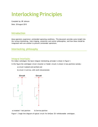
  • 1. Interlocking Principles Compiled by: BP Johnson Date: 28 August 2015 Introduction Many operators experience unintended operating conditions. This document provides some insight into the various interlocking, inter-tripping, protection and control philosophies, and how these should be integrated with one another to prevent unintended operations. Interlocking philosophy Integral Interlocks For indoor switchgear the basic integral interlocking principle is shown in figure 1. In this figure the switchgear circuit (incomer or feeder circuit) is shown in two positions namely:- a) circuit isolated and earthed and b) circuit in service, with earth disconnected. a) Isolated / test position b) Service position Figure 1. Single line diagram of typical circuit for UniGear ZS1 withdrawable switchgear.
  • 2. In the isolated position the circuit breaker is racked to the test position, disconnecting if from the main busbar. The withdrawing action of the circuit breaker acts like the isolator. Once the circuit breaker is withdrawn (isolated), it is then possible to earth the cable circuit by closing the circuit earth switch. Once the cable circuit earth is closed it is not possible to insert the circuit breaker due to an internal integral interlock. To connect the cable circuit to the main busbar, the cable earth is first opened and then the circuit breaker can be inserted (racked in). Once racked in the circuit breaker can be closed. The integral interlock will prevent the cable earth from being applied once the circuit breaker is racked in. a) Isolated / test position b) Service position Figure 2. Single line diagram of typical circuit for switchgear using isolators. In figure 2, the same principles are used for outdoor switchgear or for fixed pattern switchgear. However in these cases isolation is achieved through the use of disconnectors. The earth switch is then interlocked with the isolators. Key Interlocks Trapped key interlocks are used together with integral interlocks to interlock remote devices with local devices. I.e. interlock between a remote earth switch and a local circuit breaker racking mechanism. Trapped key interlocks are used as a backup system to guide operators and are normally optional items. Figure 3. Shows a basic trapped key interlock system used across transformers to prevent an earth applied to a back-feed or an incoming circuit.
  • 3. Figure 3. Basic interlocking system for switchgear In this example the earth switches cannot be closed until the local circuit breaker and the remote circuit breaker is withdrawn. The sequence of interlocks are shown in figure 4. Figure 4. Sequence of operation of a typical interlocking system
  • 4. In the above sequence the keys are moved from the circuit breaker to the earth switches to enable the earth switches. While the earth switch is closed the key is trapped preventing the key from being moved back to the circuit breaker to enable racking. Only once the earth is removed can the key be returned to the circuit breaker which will enable the circuit breaker to be racked. Electrical Interlocks Similar to the key interlock it is possible to install electro mechanical interlocks instead of trapped key interlocks. Electro-mechanical interlocks work on the principle that they block or enable operation depending on the state of remote equipment. This philosophy of blocking and enabling is a fail-safe philosophy that does not enable access to any equipment until the right conditions are met. Another important attribute of a fail-safe interlock is that it will disable access until the auxiliary voltage is present. Figure 5. Provides an example of a fail-safe interlock system. In this system the apparatus operating access shown in yellow is blocked when the coil is de-energised or when the auxiliary voltage is not present. a) Access blocked when coil de-energised b) Access enabled when coil energised Figure 5. Example of a fail-safe interlock It is important to provide some examples of a fail-safe electromechanical interlocking system, and an interlocking system that is not fail-safe. Examples of a fail-safe system  Enable the racking of the circuit breaker by means of energizing an electro-solenoid. If the solenoid is not energized the racking is blocked, thereby the interlock is considered fail-safe.  Enable the operation of an earth switch by means of an electro-solenoid. If the solenoid is not energized the closing operation is blocked, thereby the interlock is considered fail-safe.
  • 5. Examples of a system that is not fail-safe, and therefore cannot be considered suitable for interlocking  Disable the racking of the circuit breaker by means of energizing an electro-solenoid. If the solenoid is energized the racking is blocked, thereby the interlock is not considered fail-safe.  Disable the operation of an earth switch by means of an electro-solenoid. If the solenoid is energized the closing operation is blocked, thereby the interlock is not considered fail-safe.  Sending a trip signal to a circuit breaker if an earth switch is closed or opened. In this case it is possible to close the earth switch under live conditions. The remote CB is expected to open and clear the unwanted condition, however many things can go wrong, i.e. the earth switch may be able to close before the CB opens, the CB may not open due to loss of auxiliary power, or some due to some fault on the CB mechanism. Another possibility is that it may be possible to close the CB onto an earth before the CB is tripped by the earth switch contact. Lastly a open CB is not considered an isolating point. Racking the CB to the test position or an isolator should be used as an isolating point before closing the earth switch. Interlocking barriers Potential interlocking barriers may exist between two circuits. These barriers are not intended but naturally exist due to the plant configuration, design and layout. Figure 6, provides a graphical example of how unintended barriers may exist between two apparatus connected together. Figure 6. Graphical representation of potential interlocking barriers
  • 6. In the above example two circuits are connected together. The once circuit is a withdrawable type circuit while the other uses disconnectors. The circuits may be separated by distance as well as by a transformer. These common differences present potential barriers, where it becomes difficult to interlock one system with another. Listed below are common potential barriers that may exist between apparatus:  Different type of apparatus (Withdrawable and fised pattern designs)  Indoor and outdoor apparatus connected together  Distance between the apparatus. If the distance is great then electrical interlocks will not work, and if too gfreat then mechanical interlocks become impracticle.  Distance created by location such as surface mounted or underground mounted apparatus  Distance created by different access rights between different substations where the equipment is mounted  Items connected via transformers  Network configuration, T-Offs, ring feeds, or by-pass circuits  Different procurement times of apparatus. For example items purchased at a different times may result in interlocks not being compatible with each other or unknown to each other, or based on different interlocking principles being applied by the engineering staff who procured the apparatus.  Technical limitations of some apparatus where it may not be possible to accommodate fail safe electrical or mechanical interlocks. Safety Locks Safety locks are locks that the operator can fit to the switchgear. Safety locks are normally the operators own personal locks or locks dedicated for this purpose. The important thing about safety locks is that once applied the operator can then keep or store the key in a safe place while working on the equipment. In this regard the following points can be made about safety locks.  Facilities for safety locks are mandatory.  No other interlocks (trapped key locks, electro-mechanical locks or integral locks should inhibit the possibility to fit safety locks. That is to say that it should always be possible to fit safety locks irrespective of the presence or not of other interlocks.  No other interlocks should be used as safety interlocks. In some cases it may be possible to fit a key interlock to be used as a safety interlock, however in these cases it should still be possible for an operator to fit his own safety lock. It is also important to mention that in these cases some confusion may enter into the interlocking philosophy in deciding whether the lock is a safety lock (used for safety) or a interlock (used to prevent mal-operation).
  • 7. Protection and Inter-tripping philosophy In addition to interlocking systems, protection and inter-tripping devices may be employed to trip circuit breakers or prevent closing of circuit breakers. These systems are generally used to prevent damage to equipment and not as safety devices, as the circuit breaker is not considered a safe isolating mechanism. Typical interlocking mechanisms include trip send, trip receive, master trip, and close inhibit protection functions. Operating philosophy The operating philosophy of an electrical system normally includes the following elements:  Basic understanding of electrical systems for electricians  Signage to guide the operators, including warning signs, clear identification of equipment, and PPE requirements.  Information on how the equipment is connected to the greater system such as single line diagrams, mimic diagrams, and/or referral to a higher level controller / control room.  Safety training and competency certification of electrical staff and operators to operate equipment within the greater electrical system.  Isolation, earth lock out and tag procedures used within the greater electrical system. A common practice is to certify operators frequently, (annually) to operate the system, and only use certified operators to operate the system. A common misconception is that electrically qualified engineers and technicians will be able to operate the system, however this is not necessarily true as they may not be familiar with the intricacies of the system. The result is that suppliers, and engineers may mal-operate the system. To avoid this situation companies use a certification process for operators, where only operators with valid current certification may operate the system. A variation of the above is where the system is so large and/or complex that operators are then certified to operate only certain parts of the system. For example the system can be split for example to primary plant, tertiary and secondary plant, or transmission and distribution, or by some other logical divide. Control philosophy The control philosophy of an electrical system includes one or more of the following attributes:  A overall view of the greater electrical system  An understanding of the sequence of operation of various apparatus in order to safely isolate and earth any part of the system.  A feedback and review system that allows for identification of the root cause, and facilitates improvements to the existing operating system.
  • 8. A common practice to achieve such systems is to use a control room where all operating decisions are reviewed and directed from a central control room. The controller will have the ability to view the greater network and identify the sequence of operation. Hierarchy or philosophies For safe operation the following hierarchy of philosophies is recommended:  Control philosophy  Operating philosophy  Interlocking philosophy  Inter-tripping and protection philosophy In this hierarchy the control philosophy is the first line of defense in determining the correct operating procedure. The next line of defense will be the operating philosophy. This is to say that should the controller provide incorrect or unclear instructions the operators still follows a procedure that ensures personal safety first and then equipment reliability. The next line of defense is the interlocking system. This system when present aims to protect personnel from harm. The last line of defense is the inter-locking and protection system. This system aims to clear faults when they occur in the quickest possible time. The hierarchy of philosophies can include additional layers to improve safety to a higher level, but should as a minimum include the above four layers. Recommendations We envisage that many plants cannot solely rely on the installed interlocking to protect and guide operators for safe operation of equipment. The reason is that interlocks may not be consistently implemented across the whole electrical system. In addition the reliability of interlocking systems may not be sufficient to consistently work without failure, and it may be possible to intentionally over-ride interlocks with the use of tools. The end result is that the operator can never be 100% sure of the current state of the interlocking system. We therefore recommend that customers review the operating and control philosophies for safe operation of the electrical apparatus, irrespective of interlocking systems.