The document provides the engineering problem definition, requirements, and analysis for designing a turbojet engine. It defines the operating conditions, constraints, and performance parameters to analyze. An engineering analysis is then presented using MATLAB code to calculate temperatures, pressures, mass flows, and other parameters across the engine for a range of compressor pressure ratios from 2 to 40. Graphs of key parameters like thrust, temperatures, mass flow, and efficiency are plotted to identify the highest performing compressor pressure ratio design.
Just Call Vip call girls dharamshala Escorts ☎️9352988975 Two shot with one g...
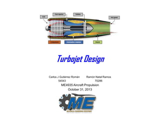
Turbojet Design Project
1. Turbojet Design
Carlos J Gutiérrez Román
54543
Ramón Natal Ramos
70286
ME4935 Aircraft Propulsion
October 31, 2013
2. Problem Definition
Design a turbojet engine under the following conditions:
Altitude of 37000 ft.
The pressure ratio across the compressor πc.
The Mach number M0=2.0.
Maximum enthalpy ratio τλ=7.0
Fuel type is hydrocarbon with QR = 42800 kJ/kg
For a range of compressor pressure ratios, namely 2<πc<40, calculate:
a) The pressure and temperatures at each principal state in kPa and K.
b) Air mass flow rate.
c) The velocity at the nozzle exit.
d) Power of the turbo-components.
e) Fuel flow rate necessary to power the engine.
f) Performance parameters (SFC, TSFC, thermal efficiency, propulsive
efficiency).
Defined problem gives us a start point for assumptions & correct analysis.
ME4935 FA-13
ME 5930 – FA12
2
3. Technology Assessment
http://en.wikipedia.org/wiki/Turbojet
Simple explanations on how a turbojet works.
http://web.mit.edu/16.unified/www/FALL/thermodynamics/notes/node85.html
Very specific explanations of the thermodynamic cycle of a turbojet.
http://www.stanford.edu/~cantwell/AA283_Course_Material/AA283_Course_Notes/Ch
_04_Turbojet_Cycle.pdf
Complete description and formulas for turbojet design, from thermodynamics to
compressor geometry.
It’s always a good idea to understand the current trends to better guide the design.
ME4935 FA-13
ME 5930 – FA12
3
4. Applicable Engineering Principles
Thermodynamics Analysis.
The gas generator is composed of a compressor, a turbine, a pair of nozzles and a
burner. All are analyzed thermodynamically to find the total pressures and temperatures.
With these data pressure and temperatures ratios, air fuel ratio and power of the turbine
and compressor are calculated.
Fluid dynamics
The compressor geometry depends on the angles the fluid must take when approaching
the blades. A fluid dynamics analysis was made to obtain the mean radius of the
compressor blades. With this data nozzles areas and mass flow are calculated.
Previously learned topics are the key elements to analyze the given problem.
ME4935 FA-13
ME 5930 – FA12
4
5. Engineering Requirements
The engine must be able to operate at an altitude of 37000 ft.
The pressure ratio across the compressor πc must produce the
maximum thrust for each pound of fuel.
The engine must be able to operate at a Mach number of M0=2.0.
Maximum enthalpy ratio possible for this engine is τλ= 7.0
Fuel type it will use is hydrocarbon with QR = 42800 kJ/kg.
It can not violate any fluid mechanics or thermodynamics laws.
Turbine inlet temperature must not exceed 2000K.
Constraints creates the boundaries for the design requirements.
ME4935 FA-13
ME 5930 – FA12
5
7. Proposed Concepts
For the given conditions we will design a turbojet engines that delivers
the maximum thrust possible.
Instead of using three different compressor pressure ratios we write a
Matlab script program that varies the compressor ratio for the following
range of values: 2<πc<40
Our program utilizes the compressor temperature ratio to calculate the
mean radius of the compressor and the corresponding inlet area.
Since the temperature ratio depends of the pressure ratio, the program
returns the optimal mean radius for a given πc.
For all the different values of πc our program also optimizes the
corresponding inlet and nozzle areas, inlet mass flow and fuel ratio.
Plotting the most relevant data, we can decide which compressor
pressure ratio returns the best performance from the turbojet engine.
Technology and logical assumptions ease the design process from the start
ME4935 FA-13
ME 5930 – FA12
7
8. Engineering Analysis
•
•
•
•
•
•
•
•
•
•
•
•
•
•
•
•
•
•
•
clear all
clc
%TurboJet Engine Analysis
Pidmax = 1;
T0 = 273.15-56.5;
M0 = 2;
R = 285;
kc = 1.4;
kh = 1.33;
V0 = sqrt(kc*R*T0)*M0;
TaoA = 7;
QR = 42800000;
Cpc = 1004;
Cph = 1156;
nm = 0.99;
h = (37000*0.3048);
P0 = 101325*(1-0.0000225577*(h))^5.25588;
Pt0 = P0*(1+((kc-1)/2)*M0^2)^((kc/(kc-1)));
Tt0 = T0*(1+((kc-1)/2)*M0^2);
•
•
% Inlet Diffuser
Pid = Pidmax*(1-0.075*(M0-1)^1.35);
Specification 5008B
Pt2 = Pt0*Pid;
Tt2 = Tt0;
•
•
ME4935 FA-13
ME 5930 – FA12
%Maximum Inlet Total Pressure Recovery (ideal)
%Temperature at initial conditions
%Mach number at initial conditions
%Cold Section ONLY
%Hot Section ONLY
%Speed at initial conditions
%Tao Lambda
%Mechanical Efficiency
%Altitude 37,000 ft. converted to meters
%Air Pressure and Altitude above Sea Level formula
%Total pressure at initial conditions
%Total temperature at initial conditions
% nr = (1-0.075*(M0-1)^1.35 ... Pid = Pidmax x nr
---> Military
%Temperature doesnt change in ducts
8
9. Engineering Analysis
•
•
•
•
•
•
•
•
•
•
•
•
•
•
•
•
•
•
•
•
•
•
•
•
•
•
% Compressor
Pic = 2:40;
value )
ec = 0.9;
Pt3 = Pt2.*Pic;
Tt3 = Tt2.*(Pt3./Pt2).^((kc-1)/(kc.*ec));
TaoC = Tt3./Tt2;
nc = (Pic.^((kc-1)./kc)-1)./(TaoC-1);
%Compressor pressure ratio. Pic can vary from 2 to 40 ( 40 max
%Compressor Polytropic efficiency
%Pressure at compressor exit / combustor entrance
%Temperature at compressor exit / combustor entrance
%Compressor temperature ratio
%Compressor efficiency
% Burner (Combustors)
Mb = 0.2;
E = 1;
nb = 0.98;
Pib = 1-(E.*(0.5.*kc).*Mb.^2);
Pt4 = Pt3.*Pib;
Tt4 = (TaoA.*T0.*Cpc)./Cph;
h0 = T0.*Cpc;
TaoR = Tt2./T0;
f = (TaoA-(TaoR.*TaoC))./(((QR.*nb)./h0)-TaoA);
%Burner efficiency
%Burner pressure ratio
%Pressure at combustor exit / turbine entrance
%Temperature at combustor exit / turbine entrance
%Ambient enthalpy h0 = Cpc*T0
%Compressor temperature ratio
%fuel-air ratio
% Turbine
et = 0.9;
%Turbine polytropic efficiency
TaoT = 1-((TaoR.*(TaoC-1))./((1+f).*TaoA)); %Turbine temperature ratio
Tt5 = Tt4.*TaoT;
%Temperature at tubine exit / nozzle entrance
PiT = (TaoT).^((kh)./((kh-1).*et));
%Turbine Pressure ratio
Pt5 = Pt4.*(Tt5./Tt4).^((kh)./((kh-1).*et));%Pt4*PiT; Pressure at turbine exit / nozzle entrance
nt = (1-TaoT)./(1-TaoT.^(1./et));
%Turbine adiabatic efficiency
ME4935 FA-13
ME 5930 – FA12
9
10. Engineering Analysis
•
•
•
•
•
•
•
•
•
•
•
•
% Outlet Nozzle
P9 = P0;
NPR = Pt5./P9;
•
•
•
•
•
•
•
•
•
•
%Inlet Design & Dimensions
D2 = rm*4;
%Diameter at end of nozzle section = 4 times Compressor mean radius
A2 = (pi./4).*D2.^2;
%Area at End of inlet (2)
M1 = M0;
%For Supersonic flight
Ati = A2./((1./M2).*((1+((kc-1)./2).*M2.^2)./((kc+1)./2)).^((kc+1)./(2.*(kc-1))));
%Inlet throat area
A1 = Ati.*((1./M0).*((1+((kc-1)./2).*M0.^2)./((kc+1)./2)).^((kc+1)./(2.*(kc-1))));
%Inlet area (1)
A0 = A1;
%For supersonic flight intet area = A0
m0 = A0.*((P0./(R.*T0)).*V0);
%Mass flow
D1 = ((4./pi).*A1).^(1/2);
%Inlet Diameter
Dti = ((4./pi).*Ati).^(1/2);
%Inlet throat diameter
%Perfectly Expanded
%Nozzle Pressure Ratio
%Compressor Design & Dimensions
M2 = 0.4;
%Assuming subsonic speed before compressor
w = 30000;
%Angular Velocity
Beta = -25;
%Beta angle
Alfa = 12;
%Alfa angle
T2 = Tt2./(1+((kh-1)./2).*M2.^2);
%Temperature at inlet exit
U = ((TaoC-1)./(1+.6.*(tan(Beta)-tan(Alfa))).*Cpc.*Tt2).^(1/2);
rm = U./(w.*(2.*pi./60));
%Mean Radius
ME4935 FA-13
ME 5930 – FA12
10
11. Engineering Analysis
•
•
•
•
•
•
•
•
%Nozzle Design & Dimensions
mg = m0.*(1+f);
M9 = (((NPR).^((kh-1)./kh)-1)./((kh-1)./2)).^(1/2);
%Mach number at nozzle outlet
T9 = Tt5./(1+((kh-1)./2).*M9.^2);
%Temperature at nozzle outlet
V9 = M9.*(kh.*R.*T9).^(1/2);
%Speed at nozzle outlet
A9 = mg./((P9./(R.*T9)).*V9);
%Exhaust mass flow
Atn = A9./((1./M9).*((1+((kh-1)./2).*M9.^2)/((kh+1)/2)).^((kh+1)/(2.*(kh-1))));
%Nozzle throat area
Dtn = ((4./pi).*Atn).^(1/2);
%Nozzle throat Diameter
•
•
•
•
•
•
•
•
•
•
•
•
•
%Other Parameters
mf = mg-m0;
Pt = m0.*(1+f).*Cph.*(Tt4-Tt5);
Pc = Pt.*nm;
%Fuel Flow Rate
%Turbine Power
%Compressor Power
%Performance Parameters
RD = m0.*V0;
GT = (m0+mf).*V9;
F = GT-RD;
TSFC = mf./F;
nT = ((m0+mf).*V9.^2-m0.*V0.^2)./(2.*mf.*QR);
nP = 2./(1+(V9./V0));
nO = (F.*V0)./(mf.*QR);
%Ram Drag
%Gross Thrust
%Uninstalled Trust
%Thrust Specific Fuel Consumption
%Thermal Efficiency
%Propulsive Efficiency
%Overall Efficiency
ME4935 FA-13
ME 5930 – FA12
11
12. Engineering Analysis
•
•
•
•
•
•
•
•
•
•
•
•
•
•
•
•
•
•
•
•
•
•
•
•
%Plots Thrust vs Compressor Pressure Ratio
subplot(2,4,1)
plot(Pic,F);
title('Thrust vs Compressor Pressure Ratio')
xlabel('Compressor Pressure Ratio');
ylabel('Thrust (lb)');
axis([2 40 0 45000])
grid on
%Plots Tt3 and Tt5 vs Compressor Pressure Ratio
subplot(2,4,2)
plot(Pic,Tt3,Pic,Tt5);
title('Tt3 and Tt5 vs Compressor Pressure Ratio')
xlabel('Compressor Pressure Ratio');
ylabel('Tt3 and Tt5');
grid on
%Plots Mass flow vs Compressor Pressure Ratio
subplot(2,4,3)
plot(Pic,m0);
title('Mass flow vs Compressor Pressure Ratio')
xlabel('Compressor Pressure Ratio');
ylabel('Mass flow');
grid on
ME4935 FA-13
ME 5930 – FA12
12
13. Engineering Analysis
•
•
•
•
•
•
•
•
•
•
•
•
•
•
•
•
•
•
•
•
•
•
•
%Plots Fuel to Air ratio vs Compressor Pressure Ratio
subplot(2,4,4)
plot(Pic,f);
title('Fuel to Air ratio vs Compressor Pressure Ratio')
xlabel('Compressor Pressure Ratio');
ylabel('Fuel to Air ratio');
grid on
%Plots TSFC vs Compressor Pressure Ratio
subplot(2,4,5)
plot(Pic,TSFC);
title('TSFC vs Compressor Pressure Ratio')
xlabel('Compressor Pressure Ratio');
ylabel('TSFC');
grid on
%Plots Thermal Efficiency vs Compressor Pressure Ratio
subplot(2,4,6)
plot(Pic,nT);
title('Thermal Efficiency vs Compressor Pressure Ratio')
xlabel('Compressor Pressure Ratio');
ylabel('Thermal Efficiency');
grid on
ME4935 FA-13
ME 5930 – FA12
13
14. Engineering Analysis
•
•
•
•
•
•
•
•
•
•
•
•
•
•
•
%Plots Propulsive Efficiency vs Compressor Pressure Ratio
subplot(2,4,7)
plot(Pic,nP);
title('Propulsive Efficiency vs Compressor Pressure Ratio')
xlabel('Compressor Pressure Ratio');
ylabel('Propulsive Efficiency');
grid on
%Plots Fuel Mass Flow vs Compressor Pressure Ratio
subplot(2,4,8)
plot(Pic,mf);
title('Fuel Mass Flow vs Compressor Pressure Ratio')
xlabel('Compressor Pressure Ratio');
ylabel('Fuel mass flow');
grid on
ME4935 FA-13
ME 5930 – FA12
14
15. Engineering Analysis
4
Thrust vs Compressor Pressure Ratio
x 10
Compressor Di
1
4
Compressor Diameter
0.9
Thrust (N)
3
2
1
0.8
0.7
0.6
0.5
0.4
0
5
10
15
20
25
Compressor Pressure Ratio
30
35
40
1
1.5
Co
Compressor Pressure Ratio vs Mass flow
Compress
40
Compressor Pressure Ratio
Compressor Pressure Ratio
40
30
20
10
0
0
20
40
60
80
100
Mass flow
120
140
160
180
30
20
10
0
0.005
0.01
Graphical Analysis helps to identify the highest performing values in our design.
ME4935 FA-13
ME 5930 – FA12
15
16. Engineering Analysis
essure Ratio
Tt3 and Tt5 vs Compressor Pressure Ratio
1400
Tt3 and Tt5
1200
1000
800
600
25
re Ratio
30
35
400
40
0
5
Pressure Ratio
10
15
20
25
Compressor Pressure Ratio
30
35
40
35
40
Fuel to Air ratio vs Compressor Pressure Ratio
0.03
Fuel to Air ratio
0.025
0.02
0.015
0.01
25
re Ratio
30
35
40
0.005
0
5
10
15
20
25
Compressor Pressure Ratio
30
Optimum values for pressure ratio
ME4935 FA-13
ME 5930 – FA12
16
17. Engineering Analysis
-5
6
TSFC vs Compressor Pressure Ratio
x 10
Thermal Efficiency
0.6
0.55
Thermal Efficiency
TSFC
5.5
5
4.5
0.5
0.45
0.4
0.35
4
0.3
3.5
0
5
10
15
20
25
Compressor Pressure Ratio
30
35
0.25
40
0
5
Propulsive Efficiency vs Compressor Pressure Ratio
1.6
0.9
1.4
Fuel mass flow
1.8
0.95
Propulsive Efficiency
15
Compre
Fuel Mass Flow v
1
0.85
0.8
0.75
0.7
0.65
ME4935 FA-13
ME 5930 – FA12
10
1.2
1
0.8
0.6
0
5
10
15
20
25
Compressor Pressure Ratio
30
35
40
0.4
0
5
10
15
Compre
17
18. Engineering Analysis
essure Ratio
Thermal Efficiency vs Compressor Pressure Ratio
0.6
Thermal Efficiency
0.55
0.5
0.45
0.4
0.35
0.3
25
re Ratio
30
35
0.25
40
0
5
ssor Pressure Ratio
10
15
20
25
Compressor Pressure Ratio
30
35
40
35
40
Fuel Mass Flow vs Compressor Pressure Ratio
1.8
Fuel mass flow
1.6
1.4
1.2
1
0.8
0.6
25
re Ratio
30
ME4935 FA-13
ME 5930 – FA12
35
40
0.4
0
5
10
15
20
25
Compressor Pressure Ratio
30
18
19. πc = 40
Total
πc = 17
10
10
40
20
10
10
100
πc = 2
Weighting
Air mass flow rate
Fuel flow rate
Thrust
TSFC
Thermal efficiency
Propulsive efficiency
Baseline
Criteria
Problem Statement
Concept Selection
1
-1
1
1
0
0
60
1
0
0
0
0
1
20
Analyzing 3 different cases of compressor pressure ratio makes us take a better judgment of
which is the best for the steps to come and final design.
ME4935 FA-13
ME 5930 – FA12
19
20. Engineering Analysis
The compressor pressure ratio that develops the most thrust is πc = 17.
It’s also the best compressor pressure ratio to obtain the best TSFC.
The temperatures Tt5 and Tt3 are the same at πc = 14 which means that
our method to approximate the mean radius is very good.
For our design we chose a πc = 17 and obtained the following results:
Funin = 42,705 N
TSFC = 3.53 x10⁻⁵
ηT = 51%
ηP = 75%
ṁ0 = 108.87 kg/s
ṁf = 1.51 kg/s
ϝ = 0.0139
Pc = 6.15 x10⁷ W
Pt = 6.21 x10⁷ W
V9 = 966.89 m/s
NPR = 15.12
Using the best compressor pressure ratio yields optimum results.
ME4935 FA-13
ME 5930 – FA12
20
21. Engineering Analysis
Temperature and pressures per stage:
Stage
Tt (K)
Pt (KPa)
Total Temperatures and Pressures per stage
0
2
3
4
387.97
387.97
958.73
1371
169.47
156.76
2664.9
2590.3
5
830
327.53
With all needed parameters, parts and/or components of the turbine can be designed.
ME4935 FA-13
ME 5930 – FA12
21
24. Conclusions
Increasing the compressor pressure ratio not necessary increase the
thrust output. Air fuel ratio started deceasing after the optimum πc.
When the output temperatures of the compressor and turbine are similar
the engines returns more thrust per pound of fuel.
Increasing the air mass flow and fuel mass flow not necessary increase
the thrust output (it also depends in other factors like pressure ratio).
We have to convert all the pressure that its not consumed by the turbine
into speed to get the most thrust (perfectly expanded).
The diameter of the compressor wheel and blades depends on the
thermodynamic calculations.
ME4935 FA-13
ME 5930 – FA12
24
25. Recommendations
Being able to acquire the knowledge in class to implement to our project
the following:
Cooling of the turbine section.
Detailed design of the compressor and turbine blades.
Compare more than one type of propulsion (turbojet vs turbofan vs turboprop).
ME4935 FA-13
ME 5930 – FA12
25