

Recomendados
Recomendados
Más contenido relacionado
La actualidad más candente
La actualidad más candente (20)
Similar a Aen 201
Similar a Aen 201 (20)
Más de shivendra kumar
Último
Último (20)
Aen 201
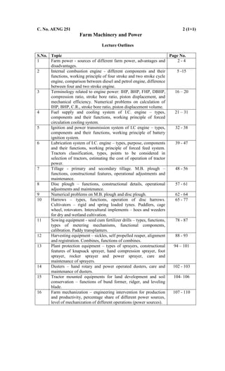
- 1. C. No. AENG 251 2 (1+1) Farm Machinery and Power Lecture Outlines S.No. Topic Page No. 1 Farm power - sources of different farm power, advantages and disadvantages. 2 - 4 2 Internal combustion engine - different components and their functions, working principle of four stroke and two stroke cycle engine, comparison between diesel and petrol engine, difference between four and two stroke engine. 5 -15 3 Terminology related to engine power: IHP, BHP, FHP, DBHP, compression ratio, stroke bore ratio, piston displacement, and mechanical efficiency. Numerical problems on calculation of IHP, BHP, C.R., stroke bore ratio, piston displacement volume. 16 – 20 4 Fuel supply and cooling system of I.C. engine – types, components and their functions, working principle of forced circulation cooling system. 21 – 31 5 Ignition and power transmission system of I.C engine – types, components and their functions, working principle of battery ignition system. 32 - 38 6 Lubrication system of I.C. engine – types, purpose, components and their functions, working principle of forced feed system. Tractors classification, types, points to be considered in selection of tractors, estimating the cost of operation of tractor power. 39 - 47 7 Tillage - primary and secondary tillage. M.B. plough – functions, constructional features, operational adjustments and maintenance. 48 - 56 8 Disc plough – functions, constructional details, operational adjustments and maintenance. 57 - 61 9 Numerical problems on M.B. plough and disc plough. 62 - 64 10 Harrows – types, functions, operation of disc harrows. Cultivators – rigid and spring loaded tynes. Puddlers, cage wheel, rotovators. Intercultural implements – hoes and weeders for dry and wetland cultivation. 65 - 77 11 Sowing equipment - seed cum fertilizer drills – types, functions, types of metering mechanisms, functional components, calibration. Paddy transplanters. 78 - 87 12 Harvesting equipment – sickles, self propelled reaper, alignment and registration. Combines, functions of combines. 88 - 93 13 Plant protection equipment – types of sprayers, constructional features of knapsack sprayer, hand compression sprayer, foot sprayer, rocker sprayer and power sprayer, care and maintenance of sprayers. 94 – 101 14 Dusters – hand rotary and power operated dusters, care and maintenance of dusters. 102 - 103 15 Tractor mounted equipments for land development and soil conservation – functions of bund former, ridger, and leveling blade. 104- 106 16 Farm mechanization – engineering intervention for production and productivity, percentage share of different power sources, level of mechanization of different operations (power sources). 107 - 110
- 2. 2 Lecture No.1 Farm power - sources of different farm power, advantages and disadvantages. 1.0 Farm power Various types of agricultural operations performed on a farm can be broadly classified as: 1. Tractive work – such as seed bed preparation, cultivation, harvesting and transportation. 2. Stationary work- such as silage cutting, feed grinding, threshing, winnowing and lifting of irrigation water. These operations are done by different sources of power, namely human, animal, mechanical power (oil engines and tractors), electrical power and renewable energy (solar energy, biogas, biomass and wind energy). 1.1 Human power Human beings are the main sources of power for operating small tools and implements at the farm. They are also employed for doing stationary work like threshing, winnowing, chaff cutting and lifting irrigation water. Of the total rural population in India, only 30% is available for doing farm work. The indications are that the decline in number of labourers employed for agriculture. On an average, a man develops nearly 0.1 horse power (hp). Advantages: Easily available and used for all types of work. Disadvantages: Costliest power compared to all other farms of power, very low efficiency, requires full maintenance when not in use and affected by weather condition and seasons. 1.2 Animal power The most important source of power on the farm all over the world and particularly in India is animal. It is estimated that, nearly 80% of the total draft power used in agriculture throughout the World is still provided by animals. India is having 22.68 crore cattle, which is the highest in the World. Mainly, bullocks and buffaloes happen to be the principle sources of animal power on Indian farms. However, camels, horses, donkeys and elephants are also used for the farm work. The average force a bullock can exert is nearly
- 3. 3 equal to one tenth of its body weight. Power developed by an average pair of bullocks is about 1 hp for usual farm work. Advantages: 1.Easily available. 2.Used for all types of work. 3.Low initial investment. 4.Supplies manure to the field and fuels to farmers. 5.Live on farm produce. Disadvantages: 1.Not very efficient. 2.Seasons and weather affect the efficiency. 3.Cannot work at a stretch. 4.Require full maintenance when there is no farm work. 5.Creates unhealthy and dirty atmosphere near the residence. 6.Very slow in doing work. 1.3 Mechanical power It is available through tractors, power tillers and oil engines. The oil engine is a highly efficient device for converting fuel into useful work. The efficiency of diesel engine varies between 32 and 38%, whereas that of the carburetor engine (Petrol engine) is in the range of 25 and 32%. In recent years, diesel engines, tractors and power tillers have gained considerable popularity in agricultural operations. It is estimated that, about one million tractors of 25 hp range are in use for various agricultural operations in India. Similarly, total number of oil engines of 5 hp for stationery work is 60 lakhs. Normally, stationery diesel engines are used for pumping water, flour mills, oil ghanis, cotton gins, chaff cutter, sugarcane crusher, threshers and winnowers etc., Advantages: Efficiency is high; not affected by weather; cannot run at a stretch; requires less space and cheaper form of power. Disadvantages: Initial capital investment is high; fuel is costly and repairs and maintenance needs technical knowledge. 1.4 Electrical power Now-a- day‟s electricity has become a very important source of power on farms in various states of the country. Electrical power is used mostly for
- 4. 4 running electrical motors for pumping water, dairy industry, cold storage, farm product processing, and cattle feed grinding. It is clean source of power and smooth running. The operating cost remains almost constant throughout its life. Its maintenance and operation need less attention and care. On an average, about 1/10th of the total electrical power generated in India, is consumed for the farm work, approximately it is 4600 megawatt. Advantages: Very cheap form of power; high efficiency; can work at a stretch; maintenance and operating cost is very low and not affected by weather conditions. Disadvantages: Initial capital investment is high; require good amount of technical knowledge and it causes great danger, if handled without care, 1.5 Renewable energy It is the energy mainly obtained from biomass; biogas, solar and wind are mainly used in agriculture for power generation and various agricultural processing operations. It can b used for lighting, power generation, water heating, drying, greenhouse heating, water distillation, refrigeration and diesel engine operation. This type of energy is inexhaustible in nature. The availability of wind energy for farm work is quite limited. Where the wind velocity is more than 32 kmph, wind mills can be used for lifting water. Main limitation for this source is uncertainty. Average capacity of a wind mill would be about 0.5 hp. There are about 2540 windmills in India. It is the cheapest sources of farm power available in India.
- 5. 5 Lecture No.2 Internal combustion engine - different components and their functions, working principle of four stroke and two stroke cycle engine, comparison between diesel and petrol engine, difference between four and two stroke engine. Heat engine is a machine for converting heat, developed by burning fuel into useful work (or) it is equipment which generates thermal energy and transforms it into mechanical energy. Heat engine is of two types: (i) External combustion engine, and (ii) Internal combustion engine. 2.0 External combustion engine: It is the engine designed to derive its power from the fuel, burnt outside the engine cylinder. Here combustion process uses heat in the form of steam, which is generated in a boiler, placed entirely separate from the working cylinder. 2.1 Internal combustion engine (I. C. Engine): It is the engine designed to derive its power from the fuel, burnt within the engine cylinder. Here combustion of fuel and generation of heat takes place within the cylinder of the engine. 2.2 Principle of I.C. Engine A mixture of fuel with correct amount of air is exploded in an engine cylinder which is closed at one end. As a result of explosion, heat is released and this causes the pressure of the burning gases to increase. This pressure increase, forces a close fitting piston to move down the cylinder. This movement of piston is transmitted to a crankshaft by a connecting rod so that the crankshaft turns a flywheel. To obtain continuous rotation of the crankshaft this explosion has to be repeated. Before this, the burnt gases have to be expelled from the cylinder. At the same time the fresh charge of fuel and air must be admitted and the piston must be returns back to its starting position. This sequence of events is known as working cycle. 2.3 Working of I.C. Engine I.C. engine converts the reciprocating motion of piston into rotary motion of the crankshaft by means of connecting rod. The piston which reciprocates in the cylinder is very close fit in the cylinder. Rings are inserted in the circumferential grooves of the piston to prevent leakage of gases from sides
- 6. 6 of the piston. Usually a cylinder is bored in a cylinder block. A gasket, made of copper sheet or asbestos is inserted between the cylinder and the cylinder head. The combustion space is provided at the top of the cylinder head where combustion takes place. There is a rod called connecting rod for connecting the piston and the crankshaft. A pin called gudgeon pin or wristpin is provided for connecting the piston and the connecting rod of the engine. The end of the connecting rod which fits over the gudgeon pin is called small end of the connecting rod. The other end which fits over the crank pin is called big end of the connecting rod. The crankshaft rotates in main bearings which are fitted in the crankcase. A flywheel is provided at one end of the crankshaft for smoothening the uneven torque, produced by the engine. There is an oil sump at the bottom of the engine which contains lubricating oil for lubricating different parts of the engine (Fig.1). Fig. 1. Working components of I.C.Engine 2.4 Engine components Internal combustion engine consists of the following parts (Fig.2): Cylinder: It is a part of the engine which confines the expanding gases and forms the combustion space. It is the basic part of the engine. It provides space in which piston operates to suck the air or air-fuel mixture. The piston compresses the charge and the gas is allowed to expand in the cylinder, transmitting power for useful work. Cylinders are usually made of high grade cast iron.
- 7. 7 Fig. 2.Components of I.C.Engine Cylinder block: It is the solid casting which includes the cylinder and water jackets (cooling fins in the air cooled engines). Cylinder head: It is detachable portion of an engine which covers the cylinder and includes the combustion chamber, spark plugs and valves. Cylinder liner or sleeve: It is a cylindrical lining either wet or dry which is inserted in the cylinder block in which the piston slides. Cylinder liners are fitted in the cylinder bore and they are easily replaceable. The overhauling and repairing of the engines, fitted with liners is easy and economical. Liners are classified as: dry liner, and wet liner. Dry liner makes metal to metal contact with the cylinder block casting. Wet liners come in contact with the cooling water, whereas dry liners do not come in contact with cooling water. Piston: It is a cylindrical part closed at one end which maintains a close sliding fit in the engine cylinder. It is connected to the connecting rod by a piston pin. The force of the expanding gases against the closed end of the piston, forces the piston down in the cylinder. This causes the connecting rod to rotate the crankshaft. Cast iron is chosen due to its high compressive strength, low coefficient of expansion, resistance to high temperature, ease of
- 8. 8 casting and low cost. Aluminum and its alloys are preferred mainly due to its lightness. Head (crown) of piston: It is top of the piston. Skirt: It is that portion of the piston below the piston pin which is designed to absorb the side movements of the piston. Piston ring: It is a split expansion ring, placed in the groove of the piston. Piston rings are fitted in the grooves, made in the piston. They are usually made of cast iron or pressed steel alloy. The functions of the ring are as follows: (a) It forms a gas tight combustion chamber for all positions of piston. (b)It reduces contact area between cylinder wall and piston wall for preventing friction losses and excessive wear. (c) It controls the cylinder lubrication. (d)It transmits the heat away from the piston to the cylinder walls. Piston rings are of two types: (a) Compression ring and (b) Oil ring. (a) Compression ring. Compression rings are usually plain, single piece and are always placed in the grooves, nearest to the piston head. (b) Oil ring. Oil rings are grooved or slotted and are located either in lowest groove above the piston pin or in a groove above the piston skirt. They control the distribution of lubrication oil in the cylinder and the piston. They prevent excessive oil consumption also. Oil ring is provided with small holes through which excess oil returns back to the crankcase chamber. Piston pin: It is also called wrist pin or gudgeon pin. Piston pin is used to join the connecting rod to the piston. It provides a flexible or hinge like connection between the piston and the connecting rod. It is usually made of case hardened alloy steel. Connecting rod: It is a special type of rod, one end of which is attached to the piston and the other end to the crankshaft. It transmits the power of combustion to the crankshaft and makes it rotate continuously. It is usually made of drop forged steel.
- 9. 9 Crankshaft: It is the main shaft of an engine which converts the reciprocating motion of the piston into rotary motion of the flywheel. Usually the crankshaft is made of drop forged steel or cast steel. The space that supports the crankshaft in the cylinder block is called main journal, whereas the part to which connecting rod is attached is known as crank journal. Fly wheel: Fly wheel is made of cast iron. Its main functions are as follows: (a) It stores energy during power stroke and returns back the same energy during the idle strokes, providing a uniform rotary motion by virtue of its inertia. (b) It also carries ring gear that meshes with the pinion of the starting motor. (c) The rear surface of the flywheel serves as one of the pressure surfaces for the clutch plate. (d) Engine timing marks are usually stamped on the flywheel, which helps in adjusting the timing of the engine. (e) Some times the flywheel serves the purpose of a pulley for transmitting power. Crankcase: The crankcase is that part of the engine which supports and encloses the crankshaft and camshaft. It provides a reservoir for the lubricating oil of the engine. Cam shaft: It is a shaft which raises and lowers the inlet and exhaust valves at proper time. Camshaft is driven by crankshaft by means of gears, chains or sprockets. The speed of the camshaft is exactly half the speed of the crankshaft in four stroke engine. Camshaft operates the ignition timing mechanism, lubricating oil pump and fuel pump. It is mounted in the crankcase, parallel to the crankshaft. Timing gear: Timing gear is a combination of gears, one gear of which is mounted at one end of the camshaft and other gear on the end of the end of the crankshaft. Camshaft gear is bigger in size than that of the crankshaft gear and it has twice as many teeth as that of the losing crankshaft gear. For this reason, this gear is commonly called Half time gear. Timing gear controls the timing of ignition, timing of opening and closing of valves as well as fuel injection timing.
- 10. 10 Inlet manifold: It is that part of the engine through which air or air-fuel mixture enters into the engine cylinder. It is fitted by the side of the cylinder head. Exhaust manifold: It is that part of the engine through which exhaust gases go out of the engine cylinder. It is capable of with-standing high temperature of burnt gases. It is fitted by the side of the cylinder head. 2.5 Internal engine classification Internal combustion engines are classified in two types depending on the period required to complete a cycle of operation. They are four stroke and two stroke engines. 1. When the cycle is completed in two revolutions of the crankshaft, it is called four stroke cycle engines. 2. When the cycle is completed in one revolution of the crankshaft, it is called two stroke cycle engines. I.C. engines are of two types: (i) Petrol engine (carburetor type, spark ignition engine), and (ii) diesel engine (compression ignition engine). Petrol engine: It is the engine, in which liquid fuel is atomized, vaporized and mixed with air in correct proportion before entering onto the engine cylinder during suction stroke. The fuel is ignited in the cylinder by an electric spark. Diesel engine: In this engine, during suction stroke, only air is entered into the cylinder and compressed. The fuel is injected through fuel injectors and ignited by heat of compression. 2.5.1 Working of four stroke cycle engine In four stroke cycle engine, all the events taking place inside the engine cylinder are completed in four strokes of the piston i.e., suction, compression, power and exhaust stroke (Fig.3). This engine has got valves for controlling the inlet of charge and outlet of exhaust gases. In two stroke cycle engine, all the events take place in two strokes of the piston.
- 11. 11 The four strokes of the piston are as follows: 1. Suction stroke: During this stroke, only air or mixture of air and fuel are drawn inside the cylinder. The charge enters the engine through inlet valve which remains open during admission of charge. The exhaust valve remains closed during this stroke. The pressure in the engine cylinder is less than atmospheric pressure during this stroke. 2. Compression strike: The charge taken in the cylinder is compressed by the piston during this stroke. The entire charge of the cylinder is compressed to a small volume contained in the clearance volume of the cylinder. If only air is compressed in the cylinder (as in the case of diesel engine), the fuel is injected at the end of the compression stroke. The ignition takes place due to high pressure and temperature. If the mixture of air and fuel is compressed in the cylinder (as in the case of spark ignition engine i.e., petrol engine), the mixture is ignited by spark plug. After ignition, tremendous amount of heat is generated, causing very high pressure in the cylinder which pushes the piston backward for useful work. Both valves are closed during this stroke. 3. Power stroke: During power stroke, the high pressure developed due to combustion of fuel causes the piston to be forced downwards. The connecting rod with the help of crankshaft transmits the power to the transmission system for useful work. Both valves are closed during this stroke. 4. Exhaust stroke: Exhaust gases go out through exhaust valves during this stroke. All the burnt gases go out of the engine and the cylinder becomes ready to receive the fresh charge. The inlet valve is closed and exhaust valve remains open during this stroke. The exhaust valve is closed just after the end of the exhaust stroke, and the inlet valve is opened just before the burning of the suction stroke to repeat the cycle of operation. Thus it is found that out of four strokes, there is only one power stroke and three idle strokes. The power stroke supplies necessary momentum for useful work.
- 12. 12 Fig. 3. Working of four stroke cycle engine 2.5.2 Two stroke cycle engine In such engines, the whole sequence of events i.e. suction, compression, power and exhaust are completed in two strokes of the piston and in one complete revolution of the crankshaft (Fig.4). There is no valve in this type of engine. Gas movement takes place through holes called ports in the cylinder. The crankcase of the engine is gas tight in which the crankshaft rotates. Fig. 4. Working of two stroke cycle engine
- 13. 13 First stroke (suction + compression): When the piston moves up the cylinder, it covers two of the ports, the exhaust port and the transfer port, which are normally almost opposite to each other. This traps a charge of fresh mixture in the cylinder and further upward movement of the piston compresses this charge. Further movement of the piston also uncovers a third port in the cylinder suction port. More fresh mixture is drawn through this port into the crankcase. Just before the end of this stroke, the mixture in the cylinder is ignited as in the four stroke cycle. Second stroke (Power + exhaust): The rise in pressure in the cylinder caused by the burning gases forces the piston to move down the cylinder. When the piston goes down, it covers and closes the suction port, trapping the mixture drawn into the crankcase during the previous stroke then compressing it. Further downward movements of the piston uncover first the exhaust port and then transfer port. This allows the burnt gases to flow out through exhaust port. Also the fresh mixture under pressure in the crankcase is transferred into the cylinder through transfer port during this stroke. Special shaped piston crown deflect the incoming mixture up around the cylinder so that it can help in driving out the exhaust gases. When the piston is at the top of its stroke, it is said to be at the top dead centre (TDC). When the piston is at the bottom of its stroke, it is said to be at its bottom dead centre (BDC). In two stroke cycle engine, both the sides of the piston are effective, which is not the case in case of four stroke cycle engine. Scavenging: The process of removal of burnt or exhaust gases from the engine cylinder is known as scavenging. Entire burnt gases do not go out in normal stroke, hence some type of blower or compressor is used to remove the exhaust gases in two stroke cycle engine.
- 14. 14 2.6 Comparison between diesel and petrol (carburetor) engines S.No. Diesel engine Petrol engine 1. Diesel fuels are used. Vapourizing fuels such as petrol, powerine or kerosene are used. 2. Air alone is taken in during suction stroke. Mixture of air and fuel is taken in. 3. Fuel is injected into super heated air of the combustion space where burning takes place. Air-fuel is compressed in the combustion chamber where it is ignited by an electric spark. 4. Air-fuel ratio is not constant as the quantity of air drawn into the cylinder is always the same. To vary the load and speed the quantity of fuel injected is changed. Air and fuel are almost always in the ratio of 15:1, but to vary the engine power, quantity of mixture is varied. 5. Compression ratio of the engine varies from 14:1 to 20:1. Compression ratio of the engine varies from 5:1 to 8:1. 6. Specific fuel consumption is about 0.2 kg per BHP per hour. Specific fuel consumption is about 0.29 kg per BHP per hour. 7. 4.5 litres of fuel is sufficient for nearly 20 hp hour. 4.5 litres of fuel will last about 12 hp hour. 8. Diesel engine develops more torque, when it is heavily loaded. This characteristic is not present in carburetor engines. 9. Thermal efficiency varies between 32 and 38%. Thermal efficiency varies between 25 and 32%. 10. It runs at a lower temperature on part load. Combustion gas temperature is slightly higher under part load. 11. Engine weight per horse power is high. Engine weight per horse power is comparatively low. 12. Initial cost is high. Initial cost is low. 13. Operating cost is low. Operating cost is comparatively high.
- 15. 15 2.7 Comparison between two stroke and four stroke engines S.No. Particulars Four stroke engine Two stroke engine 1. No. of power stroke one power stroke for every two revolutions of the crankshaft one power stroke for each revolutions of the crankshaft 2. Power for the same cylinder volume Small Large (about 1.5 times of 4 stroke) 3. Valve mechanism Present Ports instead of valves 4. Construction and cost Complicated and expensive Simple, cheap 5. Fuel consumption Little High (about 15% more) 6. Removal of exhaust gases Easy Difficult 7. Durability Good Poor 8. Stability of operation High Low 9. Lubrication Equipped with an independent lubricating oil circuit Using fuel, mixed with lubricating oil 10. Oil consumption Little Much 11. Carbon deposit inside cylinder Not so much Much because of mixed fuel 12. Noise Suction & exhaust is noiseless, but other working is noisy Suction & exhaust is noiseless, but other working is noise less 13. Air tight of crankcase Un necessary Must be sealed 14. Cooling Normal Chances of overheating 15. Self weight and size Heavy & large Light & small
- 16. 16 Lecture No.3 Terminology related to engine power: IHP, BHP, FHP, DBHP, compression ratio, stroke bore ratio, piston displacement, and mechanical efficiency. Numerical problems on calculation of IHP, BHP, C.R., stroke bore ratio, piston displacement volume. 3.0 Engine Terminology Fig.5. Diagram showing TDC and BDC positions Bore : Bore is the diameter of the engine cylinder (Fig.5). Stroke : It is the linear distance traveled by the piston from Top dead centre (TDC) to Bottom dead centre (BDC). Stroke-bore ratio: The ratio of length of stroke (L) and diameter of bore (D) of the Cylinder is called Stroke-bore ratio (L/D). In general, this ratio varies between 1 to 1.45 and for tractor engines, this ratio is about 1.25. Swept volume (Piston displacement): It is the volume (A x L) displaced by one stroke of the piston where A is the cross sectional area of piston and L is the length of stroke. Compression ratio: It is the ratio of the volume of the charge at the beginning of the compression stroke to that at the end of compression stroke, i.e., ration of total cylinder volume to clearance volume. Compression ration of diesel engine varies from 14:1 to 20:1, carburetor engine varies from 4:1 to 8:1. Power : It is the rate of doing work. Unit of power in SI units - Watt (Joule/sec).
- 17. 17 Horse power: It is the rate of doing work. One HP is equivalent to 75 kg-m / sec. Indicated Horse Power (IHP): it is the total horse power developed by all the cylinders and received by pistons, without friction and losses within the engine. IHP = 24500 nPLAN (for four stroke engine) IHP = n PLAN 4500 (for two stroke engine) Where P - Mean effective pressure in Kg/cm2 L- Length of the piston stroke in meters A -Cross sectional area of piston in cm2 N- rpm of the engine n - Number of cylinders in the engine Brake horse power (B.H.P): It is the horsepower delivered by the engine and is available at the end of the crankshaft and it is measured by suitable dynamometer. Frictional horse power (F.H.P): It is the power required to run the engine at a given speed with out producing any useful work. It represents the friction and pumping losses of the engine. F.H.P= I.H.P - B.H.P I.H.P = B.H.P + F.H.P Drawbar horse power (DBHP): It is the power of a tractor measured at the end of the drawbar. It is the power required to pull the loads. Brake mean effective pressure ( BMEP): It is the average pressure acting throughout the entire power strokes which are necessary to produce BHP of the engine. BMEP = 2 6075 n NAL BHP (for four stroke engine) BMEP = nNAL BHP 6075 (for two stroke engine) Thermal efficiency: It is the ratio of the horse power output of the engine to the fuel horse power.
- 18. 18 Mechanical efficiency: It is the ratio of the brake horse power to the indicated horse power. Mechanical efficiency= 100 IHP BHP Piston speed (Np) : It is the total length of travel of the piston in a cylinder in one minute. Piston speeds of the high speed tractor engine range between 300 to 500 m/m. Displacement volume (Vd) : It is the total swept volume of all the pistons during power strokes occurring in a period of one minute. Vd = ALn A – piston area L – piston stroke N – number of power strokes per minute for all cylinders. Example 1: Calculate the BHP of a 4 stroke, 4 cylinder I.C. Engine which has cylinder bore of 14 cm, stroke length of 16 cm, crankshaft speed of 1100 rpm, frictional horse power of 30, and mean effective pressure is 8 kg/cm2 . Solution: Data given: D = 14 cm ; L = 16 cm; N = 1100 rpm; FHP =30 and P=8 kg/cm2 IHP = 24500 nPLAN (for four stroke engine) IHP = 2 4 4500 110014 4 16.08 2 = 96.4 I.H.P = B.H.P + F.H.P BHP = IHP – FHP = 96.4 – 30 = 66.4 Example 2: The horse power developed at the end of crankshaft of a 4 stroke, 4 cylinder I C engines was found to be 30 HP at a speed of 1500 RPM. The mean effective pressure is 6 kg/cm2 .The stroke-bore ratio is 1.3. Find the length of stroke and diameter of bore if the mechanical efficiency is 80%. Solution: Data given: BHP =30; N = 1500; P=6 kg/cm2 ; 80%
- 19. 19 Mechanical efficiency= 100 IHP BHP IHP = BHP = 80 10030 = 37.5 IHP = 24500 nPLAN (for four stroke engine) Stroke-bore ratio = D L 1.3 L = 1.3 D IHP = 2 4 4500 1500 4 3.16 2 DD 37.5 = 4.08 D3 D = 2.1 cm L = 1.3 × 2.1 = 2.7 cm Example 3: A Four cylinder four stroke diesel engine has a cylinder diameter of 20 cm, stroke-bore ratio is 1.45, clearance volume 4508 cm3 , engine speed 250 rpm, mean effective pressure 6.8 kg/cm2 and mechanical efficiency is 75%. Calculate (i) IHP, (II) BHP (iii) Compression ratio and (iv) Swept volume. Solution: Data given: D = 20 cm; N =250; P = 6.8 kg/cm2 ; 75% clearance volume = 4508 cm2 Stroke-bore ratio = D L 1.45 Where D= 20 cm L = 1.45× 20 = 29 cm (i) IHP = 24500 nPLAN (for four stroke engine) IHP = 2 4 4500 25020 4 29.08.6 2 = 68.9 (ii) Mechanical efficiency= 100 IHP BHP BHP = 100 IHP = 100 759.68 = 51.7
- 20. 20 (iii) and (iv) Compression ratio: Swept volume + Clearence volume Clearence volume Swept volume = A x L = 2 )20( 4 29 = 9114.3 cm3 Compression ratio = 4508 45083.9114 = 3.02 Example 4: Calculate (i) IHP (ii) BHP (iii) Stroke bore ratio (iv) Compression ratio (v) Swept volume of a four stroke four cylinder I.C. engine with the following data: Cylinder size : 12.5 x 15 cm Fly wheel speed : 1200 rpm Mean effective pressure : 7 kg/cm2 Mechanical efficiency : 70% Clearance volume : 150 CC Solution Data given: L = 15 cm; D = 12.5 cm; N = 1200; P = 7 kg/cm2 ; 70% (i) IHP = 24500 nPLAN (for four stroke engine) IHP = 2 4 4500 12005.12 4 15.00.7 2 = 68.7 (ii) Mechanical efficiency= 100 IHP BHP BHP = 100 IHP = 100 707.68 = 48.1 (iii) Stroke-bore ratio = D L 5.12 15 = 1.2 (iv) and (v) Compression ratio: Swept volume + Clearence volume Clearence volume Swept volume = A x L = 2 )5.12( 4 15= 1841.5 cm3 Compression ratio = 150 1505.1841 = 13.3
- 21. 21 Lecture No.4 Fuel supply and cooling system of I.C. engine – types, components and their functions, working principle of forced circulation cooling system. 4.0 Fuel and fuel supply system Fuel is a substance consumed by the engine to produce energy. The common fuels for IC engines are: (i) petrol, (ii) power kerosene, (iii) high speed diesel oil (H.S.D oil) and (iv) light diesel oil (L.D.O) 4.1 Quality of fuel The quality of fuel mainly depends upon the following properties: (i) volatility, (ii) calorific value and (iii) ignition quality of fuel. A good fuel contains a combination of qualities such as good volatility, high antiknock value, chemical purity, and freedom from gum. 4.1.1 Volatility It is the vapourizing ability of a fuel at a given temperature. It indicates the operating characteristics of the fuel inside the engine. It is measured by means of distillation tests on the fuel. In IC engine, all the liquid fuel must be converted into vapour fuel before burning. Petrol which shows lower initial and final boiling points, compared to other fuels, vapourizes at a lower temperature. HSD oil is most difficult to vapourize. Its vapourizing temperature is higher than that of the petrol, hence the petrol vapourizes quicker than diesel oil in the engine cylinder. This helps in easy starting of petrol engines. The oil that vapourizes quickly can be distributed well in different cylinders of the engine, hence distribution of fuel in different cylinders is better in petrol engine than that of diesel engine. 4.1.2 Calorific value The heat liberated by combustion of a fuel is known as calorific value or heat value of the fuel. It is expressed in kcal/kg of the fuel. Calorific values (kcal/kg) of different fuels are as follows: 1) Petrol – 11,100 (highest) 2) Power kerosene – 10,850 3) High speed diesel oil (HSD oil)- 10,550 4) Light diesel oil (LDO oil) – 10,300
- 22. 22 4.1.3 Ignition quality It refers to ease of burning the oil in the combustion chamber. Octane number and cetane number are the measures of ignition quality of the fuel. Octane number is standard yardstick for measuring knock characteristics of fuels. Cetane number is the relative measure of the interval between the beginning of injection and auto-ignition of the fuel. The higher the cetane number, the shorter the delay interval and the greater its combustibility. Fuels with low cetane Numbers will result in difficult starting, noise and exhaust smoke. 4.2 Detonation Detonation or engine knocking refers to violent noises heard in an engine during the process of combustion after the piston has passed over the TDC. It is an undesirable combustion and results in sudden rise in pressure, a loss of power and overheating of the engine. This may cause damage to pistons, valves, gasket and other parts. Detonation is caused by improper combustion chamber, high compression pressure, early ignition timing, improper fuel and inadequate cooling arrangement. 4.3 Pre-ignition Burning of air-fuel mixture in the combustion chamber before the piston has reached the TDC is called pre-ignition. This may be due to excessive heat in the cylinder. 4.4 Fuel supply system in compression ignition engine or diesel engine The main components of the fuel supply system in diesel engine are: (i) fuel tank, (ii) primary fuel filter, (iii) fuel transfer pump or fuel lift pump, (iv) secondary fuel filter, (v) fuel injection pump, (vi) high pressure pipes, (vii) fuel injection nozzles or fuel injectors and over flow pipe (Fig.6). During engine operation, the fuel is supplied by gravity from fuel tank to the primary filter where coarse impurities are removed. From the primary filter, the fuel is drawn by fuel transfer pump. This pump is also known as fuel lift pump, is activated by a cam on the engine camshaft. The fuel lift pump forces fuel under low pressure (2.5 kg/cm2 ) through the secondary fuel
- 23. 23 filter to the injection pump, which is generally driven by the camshaft. The purpose of fuel injection pump is to deliver a metered quantity of fuel at a predetermined time under pressure (120 to 175 kg/cm2 or more) through the high pressure tubes to the injection nozzles or injectors. The fuel that leaks out from the injection nozzles passes out through leakage pipe and returns to the fuel tank through the over flow pipe. In some tractors and industrial engines, the fuel supply is by gravity and hence no fuel lift pump is provided. Two conditions are essential for efficient operation of the system: (a) The fuel should be clean, free from water, suspended dirt, sand or other foreign matter. (b) The fuel injection pump should create proper pressure, so that diesel fuel may be perfectly atomized by injectors at proper time and quantity. Fig. 6. Fuel supply system in diesel engine 4.4.1 Components of fuel supply system Fuel tank It is a storage tank of suitable size and shape, usually made of mild steel sheet. Atmospheric pressure is maintained in the tank with the help of a pin
- 24. 24 hole on the cap. Usually a wire gauge strainer is provided under the cap to prevent foreign particles. Usually a drain plug is provided at the bottom for flow of fuel. Fuel lift pump It transfers adequate amount of fuel from the fuel tank to the inlet gallery of the injection pump through fuel filter. The fuel pressure at the fuel lift pump in the range of 1.5 to 2.5 kg/cm2 . It is mounted on the body of fuel injection pump. Fuel lift pump may be (i) plunger type, (ii) diaphragm type. Fuel filter It is a device to remove dirt and solid particles from the fuel to ensure trouble free fuel supply (Fig.7). Solid particles and dust in diesel fuel are very harmful for giving a fine degree of filtration. Fuel injection equipment in diesel engines is extremely sensitive to dirt and solid particles present in fuel. It consists of a hollow cylindrical element contained in a shell, an annular space being left between the shell and the element. The filtering element consists of metal gauge in conjunction with various media such as packed fibers, woven cloth, felt, paper etc. These filters are replaced at certain intervals, specified by the manufacturer. Usually there are two filters in diesel engine: (1) Primary filter and (2) secondary filter. The primary filter removes water and coarse particle of dirt from the fuel. The secondary filter removes fine sediments from the fuel. Usually the primary filter is placed between the tank and the fuel lift pump. Fig. 7. Fuel filter Fuel injection pump It is a high pressure pump, which delivers metered quantity of fuel to each cylinder at appropriate time under pressure according to the firing order of the
- 25. 25 engine. It is used to create pressure varying from 120 to 175 kg/cm2 . Fuel injection pumps are mostly constant stroke type and in most of the tractors there is an individual pump for each cylinder. The pumps used in tractor are of two types: (i) multi element pump and (ii) (ii) Distributor (Rotor) type pump. Multi element injection pump The plunger (Fig.8) reciprocates in close fitting barrel with the help of tappet and spring. The upper part of the plunger has got helix, which makes it possible to vary the delivery of the fuel. An annular groove in the central part of the plunger facilitates the distribution of fuel over the barrel. As the plunger moves down, the fuel enters the barrel from inlet side. As plunger moves up, it closes the inlet part of the barrel and pressurizes the fuel in the barrel. This causes delivery valve to lift off its seat and allows the fuel to enter into the injection line, leading to the fuel injector. As soon as the edge of the helix uncovers the split part of the barrel, the fuel pressure quickly drops. The cam shaft of the fuel injection pump is driven directly from the engine timing gear. Fig. 8. Multi element fuel injection pump Distributor ( rotor) type pump: In this type of pump, one plunger and one barrel assembly deliver fuel not to one cylinder but to several cylinders. The plunger not only reciprocates, but rotates in a close fitting barrel. This helps in distributing fuel to a number of cylinders at a time.
- 26. 26 Fuel injector It is the component which delivers finely atomized fuel under high pressure to the combustion chamber of the engine. Modern tractor engines use fuel injectors which have multiple holes. Air cleaner It is a device, which filters and removes dust, moisture and other foreign matter from the air before if reaches the engine cylinder. Air cleaner is usually of two types: (1) Dry type air cleaner and (2) Oil bath type air cleaner. Dry type air cleaner The filtering element in this case is a type of felt. The felt has got larger surface area, reduces the air speed while passing through and consequently particle or dirt in the air is deposited on or stopped by its surface. Oil bath type air cleaner In this type of air cleaner, the incoming air impinges upon the surface of the oil, kept in a container in the lower part of the casing. The foreign particles of the air are trapped in the oil and then the air passes through a wire element before reaching the inlet manifold of the engine. The wire element also arrests the remaining dirt particles of the air. Governor Governor is a mechanical device designed to control the speed of an engine within specified limit used on tractor or stationary engine for: (i) maintaining a nearly constant speed of engine under different load conditions (ii) protecting the engine and the attached equipments against high speeds, when the load is reduced or removed. Tractor engines are always fitted with governor. There is an important difference in principle between the controls of a tractor engine and that of a motor car. In case of motor car, the fuel supply is under direct control of the accelerator pedal, but in tractor engine, the fuel supply is controlled by the governor. The operator changes the engine speed by moving the governor control lever.
- 27. 27 A governor is essential on a tractor engine for the reason that load on the tractor engine is subjected to rapid variation in the field and the operator can not control the rapid change of the engine speed without any automatic device. For example, if the load on the tractor is reduced, the engine would tend to race suddenly. If the load is increased, the engine would tend to slow down abruptly. Under these circumstances, it becomes difficult for the operator to regulate always the throttle lever to meet the temporary changes in the engine load. A governor automatically regulates the engine speed on varying load condition and thus the operator is relieved of the duty of constant regulating the throttle lever to suit different load conditions. Principle of governor Engine Governor is used for automatically controlling the speed of an engine regulating the intake of fuel or injection fuel, so that engine speed is maintained at the desired level under all conditions of loading. Governor used on tractor engine is called variable speed governor and the one used on stationary engine is called constant speed governor. Governing system is classified as: (i) hit and miss system, (ii) throttle system 4.5 Cooling System Fuel is burnt inside the cylinder of an internal combustion engine to produce power. The temperature produced on the power stroke of an engine can be as high as 1600ºC and this is greater than melting point of engine parts. The cylinder and cylinder head are usually made of cast iron and pistons in most cases are made of aluminum alloy. It is estimated that about 40 % of total heat produced is passed to the atmosphere via the exhaust, 30 % is removed by cooling system and only about 30% is used to produce useful power. 4.5.1 Bad effect of high temperature in the engine (i) Cylinder and piston may expand to such an extent that the piston would seize in the cylinder and stop the engine. (ii) Lubricating quality of the oil inside the cylinder would be destroyed due to high temperature and there may not be sucking of air in the cylinder. (iii) Pre-ignition of fuel mixture would take place and would cause engine knocking as well as loss of power.
- 28. 28 For satisfactory performance of the engine, neither overheating nor over- cooling is desirable. Experiments have shown that best operating temperature of I.C engine lies between 140ºF to 200 ºF, depending upon types of engines and load conditions. 4.5.2 Purpose of cooling (i) To maintain optimum temperature of engine for efficient operation under all conditions. (ii) To dissipate surplus heat for protection of engine components like cylinder, cylinder head, piston, piston rings and valves. (iii) To maintain the lubricating property of the oil inside the engine cylinder for normal functioning of the engine. There are two different methods of cooling: (i) air cooling and (ii) water cooling. 4.5.3 Air cooling Air cooled engines are those engines, in which heat is conducted from the working components of the engine to the atmosphere directly. In such engines, cylinders are generally not grouped in a block. Principle of air cooling The cylinder of an air cooled engine has fins to increase the area of contact of air for speedy cooling. The cylinder is normally enclosed in a sheet metal casing called Cowling. The flywheel has blades projecting from its face, so that it acts like a fan drawing air through a hole in the cowling and directing it around the finned cylinder. For maintenance of air cooling system, passage of air is kept clean by removing grasses etc. This is done by removing the cowling and cleaning out the dirt etc. by a stiff brush or compressed air. When separate fan is provided, the belt tension is to be checked and adjusted if necessary. Advantages of air cooling It is simpler in design and construction. Water jackets, radiators, water pump, thermostat, pipes, hoses etc. are not needed. It is more compact. It is comparatively lighter in weight.
- 29. 29 Disadvantages There is uneven cooling of the engine parts. Engine temperature is generally high during working period. 4.5.4 Water cooling Engines, using water as cooling medium is called “water cooled engines”. The liquid is circulated round the cylinders to absorb heat from the cylinder walls. In general, water is used as cooling liquid. The heated water is conducted through a radiator which helps in cooling the water. There are three common methods of water cooling: (i) Open jacket or hopper method, (ii) Thermo siphon method, and (iii) Forced circulation method. Forced circulation method In this method, a water pump is used to force water from the radiator to the water jacket of the engine. After circulating the entire run of water jacket, hot water goes to the radiator, where it passes through tubes surrounded by air. A fan is driven with the help of a V-belt to suck air through tubes of the radiator unit, cooling radiator water. To maintain the correct engine temperature, a thermostat valve is placed at the outer end of cylinder head. Cooling liquid is by-passed through the water jacket of the engine until engine attains the desired temperature. Then thermostat valve opens and the by-pass is closed, allowing the water to go to the radiator. The system consists of water pump, radiator, fan, fan-belt, water jacket, thermostat valve, temperature gauge and hose pipe (Fig.9). Fig. 9. Working of forced circulation cooling system
- 30. 30 Water pump It is a centrifugal type pump. It has a casing and an impeller, mounted on a shaft. The casing is usually made of cast iron. Pump shaft is made of some non-corrosive material. At the end of the shaft, a small pulley is fitted which is driven by a V-belt. Water pump is mounted at the front end of the cylinder block between the block and the radiator. When the impeller rotates, the water between the impeller blades is thrown outward by centrifugal force and thus water goes to the cylinder under pressure. The pump outlet is connected by a hose pipe to the bottom of the radiator. The impeller shaft is supported on one or more bearings. There is a seal which prevents leakage of water. Radiator Radiator is a device for cooling the circulating water in the engine. It holds a large volume of water in close contact with a large volume of air so that heat is transferred from the water to the air easily. Hot water flows into thee radiator at the top and cold water flows out from the bottom. Tubes or passages carry the water from the top of the radiator to the bottom, passing it over a large metal surface. Air flows between the tubes or through the cells at right angles to the downward flowing water. This helps in transferring the heat from the water to the atmosphere. On the basis of fabrication, the radiator is of two types: tubular type and cellular type. Tubular type radiator: It has round or flat water tubes, leading from the top to the bottom of the radiator. They may be soldered, brazed or welded in place or fastened by means of a stuffing box at each end. Fins or folded strips of light sheet metal, placed between the tubes, increase the radiating surface and improve the heat transfer. Cellular type radiator: It has a core made of short air tubes which are laid horizontally and soldered together at the ends with space between them to allow water to flow. It is also called Honey comb type radiator. Thermostat valve It is a control valve, used in the cooling system to control the flow of water when activated by a temperature signal. It is a special type of valve, which closes the inlet passage of the water connected to the radiator. The thermostat is placed in the water passage
- 31. 31 between the cylinder head and the top of radiator. Its purpose is to close this passage when the engine is cold, so that water circulation is restricted, causing the engine to reach operating temperature more quickly. Thermostats are designed to start opening at 70ºC to 75 ºC and then fully open at 82 ºC for petrol engine and 88-90 ºC for diesel engine. The thermostat valves are of two types: (a) Bellows and (b) Bimetallic. (a) Bellows type: Bellows type thermostats have got bellows, which contain a liquid like alcohol or ether. The liquid expands with the increase of temperature and raises the valve off its seat. This permits the water to circulate between the engine and the radiator. (b) Bimetallic type: It consists of a bimetallic strip. Unequal expansion of two metallic strips causes the valve to open and allows the water to flow to the radiator. Water jackets: Water jackets are cored out around the engine cylinder so that water can circulate freely around the cylinder as well as around the valve opening. Fan: The fan is usually mounted on the water pump shaft. It is driven by the same belt that drives the pump and the dynamo. The purpose of the fan is to provide strong draft of air through the radiator to improve engine cooling.
- 32. 32 Lecture No.5 Ignition and power transmission system of I.C engine – types, components and their functions, working principle of battery ignition system. 5.0 Ignition system Fuel mixture of I. C engine must be ignited in the engine cylinder at proper time for useful work. Arrangement of different components for providing such ignition at proper time in the engine cylinder is called ignition system. There are four different systems of igniting fuel: (i) ignition by electric spark i.e., spark ignition, (ii) ignition by heat of compression i.e. compression ignition, (iii) ignition by hot tube or hot bulb and (iv) ignition by open flame. Only the first two are important methods for modern engines. 5.1 Spark ignition The purpose of spark ignition is to deliver a perfectly timed surge of electricity across an open spark plug gap in each cylinder at the exact moment, so that the charge may start burning with maximum efficiency. There are two methods in spark ignition: (a) Battery ignition and (b) Magneto ignition. 5.1.1 Battery ignition Principle Battery ignition system includes two circuits: low voltage (primary circuit) and high voltage (secondary circuit). The low-voltage circuit consists of : (i) battery (ii) ignition switch (iii) a series register (IV) primary winding and (v) contact breaker. All are connected in series. The high voltage circuit consists of: (i) secondary winding (ii) distributor rotor (iii) high voltage wiring and (iv) spark plugs. They are also connected in series. Battery ignition system on a modern tractor includes a storage battery, ignition switch, high tension coil, distributor, contact breaker mechanism, condenser, spark plugs, generator and cutout. Working Electric current is supplied by the battery to the ignition circuit. When the distributor breaker points are closed, low voltage current flows through the primary winding of the ignition coil to the distributor terminal and through
- 33. 33 the breaker points to the ground. During this time, a strong magnetic field built up in the coil. When the piston is at the end of compression stroke, the distributor points are opened, the magnetic field in the coil starts collapsing. Thus, a current is induced in the primary winding of the coil, which tends to prevent break down of the magnetic field. A very high voltage is produced in the secondary winding due to sudden collapse of the magnetic field. This sudden collapse of the magnetic field in the coil, produces a very high voltage across the secondary winding terminals to a value of 20 to 24 thousand volts. The high-voltage surge is delivered to the center terminal of the distributor cap, where it is picked up by the rotor and directed to the proper spark plug. The high voltage is capable of jumping the spark across the gap of the spark plug and ignites the compressed air-fuel mixture (Fig.10). Fig. 10. Circuit diagram for battery ignition system This system of a number of components such as: (i) Spark plug (ii) Distributor (iii)Ignition coil(iv)Condenser (v) Ignition switch (vi) Dynamo and (vii) Storage battery. (1) Spark plug Spark plug ignites the air –fuel mixture in combustion chamber. It is a device for the high voltage current to jump and ignite the charge. Each spark plug consists of a threaded outer shell with an outside electrode, insulator and a copper gasket. The width of the gap between the points of the two electrodes of a spark plug should conform to the manufacturers. If the clearance is too wide, it does not give satisfactory operation. Usually the spark plug gap settings are kept between 0.5 and 0.85 mm. The higher the compression pressure, the more difficult it is for the current to jump the gap. In this case,
- 34. 34 the gap setting should be closer. In adjusting the spark plug gap, it is always the outer electrode that is bent. The central electrode is never bent, otherwise the porcelain insulator may break. Sometimes, one or more cylinders of a tractor engine do not fire, or fire irregularly. This is generally due to dirty, cracked or ground plugs. A rich mixture causes carbon deposits on the plugs. Under all circumstances, the plugs should be taken out and cleaned properly. The heat range of the spark plug is determined by the distance the heat must travel from the lower most tip of the central electrode to the engine block (via) the spark plug gasket. The farther the heat travels, the hotter the plug will run. Based on this, the spark plugs classified into two types: (a) cold plug and (b) hot plug. Cold plug has a short insulator, extending into the cylinder. It conducts the heat away from the point rapidly, allowing it to be cooled by the cylinder jacket. The short path dissipates heat quickly, so it is named as cold plug. Cold plugs are used on petrol engines. Hot plug has comparatively longer insulator, so the heat has to pass through a longer path to reach the cooling water and hence the heat is not dissipated quickly. Hot plugs are used for powerine engines. Distributor This is a rotary switch driven by the engine through gears at half the engine speed. This device used for interrupting the low voltage primary current and distributing the resulting high voltage current to the engine cylinder in proper sequence and in proper time. The main functions of distributor are: (i) it closes and opens the primary circuit. (ii) it distributes the resulting high voltage current to the engine cylinder in proper sequence and in proper time. Distributor cap is made of Bakelite or similar non-conducting material. High- tension cables connect the terminals in the distributor cap to the spark plug. Ignition coil It serves the purpose of a small transformer, which sets up low voltage (may be 6 volts) to very high voltage (may be 20,000 volts). It is necessary to jump the gap of the spark plug. The ignition coil is sealed to prevent entry of moisture which would cause short circuiting within the coil.
- 35. 35 Condenser A condenser consists of a pair of flat metal plates, separated by air. The most common type of condenser is of metal foil strips, separated by wax impregnated paper. The condenser in the distributor is connected across the contact breaker points. It is used to produce a quick collapse of the magnetic field in the coil to obtain extremely high voltage. In doing so, the condenser prevents sparking across the contact breaker points, thus preventing the points from burning. Ignition switch A switch is provided in the primary circuit for starting and stopping the engine is called ignition switch. It may be push pull type or key type. Dynamo The purpose of the dynamo is to keep the battery charged and to supply current for ignition, light and other electrical accessories. The dynamo supplies direct current to the battery and keeps it fully charged. Storage battery Storage battery is a device for converting chemical energy into electrical energy. There are several types of battery, but lead-acid battery is most common for IC engines, used for tractors and automobiles. A battery consists of plates, separators, electrolyte, container and terminal wire. Plates are of two types: (i) positive and (ii) negative. All positive and negative plates are rectangular in shape. All positive plates are connected together to form a positive group and negative plates are connected together to form a negative group. Positive plates are made of lead and antimony and negative plates are made of spongy lead. Separators are used to act as insulators between the plates to prevent them from touching each other to avoid short-circuiting. Usually separators are made of wood, rubber and cellulose fibre. Electrolyte is the chemical solution used in battery for chemical reaction. It consists of 35% sulphuric acid and 65% distilled water by weight with a specific gravity of 1.280 in fully charged condition. The specific gravity is measured by hydrometer. The electrolyte level should be 12 to 14 mm above the top edge of the plates. Specific gravity of the electrolyte should be checked at suitable interval. If the specific gravity is
- 36. 36 below 1.225, it should be charged. Container is usually made of hard rubber. The tops are covered with rubber material and sealed with a water proof compound. Terminal wires are two in number, one connects the positive terminal and other connects the negative terminal with the electric circuit. 5.2 Power transmission system Transmission is a speed reducing mechanism, equipped with several gears (Fig.11). It may be called a sequence of gears and shafts, through which the engine power is transmitted to the tractor wheels. The system consists of various devices that cause forward and backward movement of tractor to suit different field condition. The complete path of power from the engine to the wheels is called power train. Fig. 11. Power transmission system of tractor 5.2.1 Function of power transmission system (i) to transmit power from the engine to the rear wheels of the tractor. (ii) to make reduced speed available, to rear wheels of the tractor. (iii) to alter the ratio of wheel speed and engine speed in order to suit the field conditions. (iv) to transmit power through right angle drive, because the crankshaft and rear axle are normally at right angles to each other. The power transmission system consists of: (a) clutch, (b) transmission gears (c) differential, (d) final drive, (e) rear axle, (f) rear wheels. Combination of all these components is responsible for transmission of power.
- 37. 37 5.2.2 Clutch Clutch is a device, used to connect and disconnect the tractor engine from the transmission gears and drive wheels. Clutch transmits power by means of friction between driving members and driven members. Necessity of clutch in a tractor Clutch in a tractor is essential for the following reasons: (i) Engine needs cranking by any suitable device. For easy cranking, the engine is disconnected from the rest of the transmission unit by a suitable clutch. After starting the engine, the clutch is engaged to transmit power from the engine to the gear box. (ii) In order to change the gears, the gear box must be kept free from the engine power, otherwise the gear teeth will be damaged and engagement of gear will not be perfect. This work is done by a clutch. (iii) When the belt pulley of the tractor works in the field it needs to be stopped without stopping the engine. This is done by a clutch. Essential features of a good clutch (i) It should have good ability of taking load without dragging and chattering. (ii)It should have higher capacity to transmit maximum power without slipping. (iii) Friction surface should be highly resistant to heat effect. (iv) The control by hand lever or pedal lever should be easy. Types of clutch Clutches are mainly of three types: (1) Friction clutch (2) Dog clutch (3) Fluid coupling. Friction clutch (Fig.12) is most popular in four wheel tractors. Fluid clutch is also used in some tractors these days. Dog clutch is mostly used in power tillers. Friction clutch may be subdivided into three classes: (a) Single plate clutch or single disc clutch (b) Multiple plate clutch or multiple disc clutch (c) Cone clutch. Fig. 12. Single plate clutch
- 38. 38 5.2.3 Gears Speed varies according to the field requirements and so a number of gear ratios are provided to suit the varying conditions. Gears are usually made of alloy steels. As the tractor has to transmit heavy torque all the time, best quality lubricants free from sediments, grit, alkali and moisture, is used for lubrication purpose. SAE 90 oil is generally recommended for gear box. 5.2.4 Differential Differential unit (Fig.13) is a special arrangement of gears to permit one of the rear wheels of the tractor to rotate slower or faster than other. While turning the tractor on a curve path, the inner wheel has to travel lesser distance than the outer wheel. The inner wheel requires lesser power than the outer wheel, this condition is fulfilled by differential unit, which permits one of the rear wheels of the tractor to move faster than the other at the turning point. Fig.13. Tractor differential unit 5.2.5 Differential lock Differential lock is a device to join both half axles of the tractor so that even if one wheel is under less resistance, the tractor comes out from the mud etc as both wheels move with the same speed and apply equal traction. 5.2.6 Final drive Final drive is a rear reduction unit in the power trains between the differential and drive wheels.
- 39. 39 Lecture No.6 Lubrication system of I.C. engine – types, purpose, components and their functions, working principle of forced feed system. Tractors classification, types, points to be considered in selection of tractors, estimating the cost of operation of tractor power. 6.0 Lubrication System IC Engine is made of many moving parts. Due to continuous movement of two metallic surfaces over each other, there is wearing of moving parts, generation of heat and loss of power in the engine. Lubrication of moving parts is essential to prevent all these harmful effects. 6.1 Purpose of lubrication Lubrication of the moving parts of an IC Engine performs the following functions: (i) Reduces the wear and prevents seizure of rubbing surfaces (Reduce wear) (ii) Reduces the power needed to overcome the frictional resistance (Reduce frictional effect). (iii) Removes the heat from the piston and other parts (Cooling effect) (iv) Serves as a seat between piston rings and cylinder (Sealing effect) (v) Removes the foreign material between the engine working parts (Cleaning effect) Reducing frictional effect The primary purpose of the lubrication is to reduce friction and wear between two rubbing surfaces. The continuous friction produces heat which causes wearing of parts and loss of power. This can be avoided by proper lubrication, which forms an oil film between two moving surfaces. Cooling effect The heat generated by piston, cylinder and bearings is removed by lubrication to a great extent. Lubrication creates cooling effect on the engine parts. Sealing effect The lubricant enters into the gap between the cylinder liner, piston and piston rings. Thus, it prevents leakage of gases from the engine cylinder. Cleaning effect Lubrication keeps the engine clean by removing dirt or carbon from inside of the engine along with the oil.
- 40. 40 6.2 Types of Lubricants Lubricants are obtained from animal fat, vegetables and minerals. Lubricants made of animal fat, does not stand much heat. It becomes waxy and gummy which is not very suitable for machines. Vegetable lubricants are obtained from seeds, fruits and plants. Cotton seed oil, Olive oil, linseed oil and Castor oil are used as lubricant in small simple machines. Mineral lubricants are most popular for engines and machines. It is obtained from crude petroleum found in nature. Petroleum lubricants are less expensive and suitable for IC Engines. 6.3 Engine lubricating system The lubricating system of an engine is an arrangement of mechanism and devices which maintains supply of lubricating oil to the rubbing surface of an engine at correct pressure and temperature. The parts which require lubrication are: (i) cylinder walls and piston, (ii) piston pin (iii) crankshaft and connecting rod bearings (iv) cam shaft bearings (v) valves and valve operating mechanism (vi) cooling fan (vii) water pump and (viii) ignition mechanism. There are three common systems of lubrication used on stationery engines, tractor engines and automobiles: (i) splash system, (ii) forced feed system, and (iii) combination of splash and forced feed system. 6.3.1 Forced feed system In this system, the oil is pumped directly to all the moving parts (i.e., crankshaft, connecting rod, piston pin, timing gears and cam shaft) of the engine through suitable paths of oil (Fig.14). Lubricating oil pump is a positive displacement pump, usually gear or vane type, which is driven by the camshaft, forces oil from the crankcase to all crankshaft, and connecting rod bearings, cam shaft bearings and timing gears. Usually the oil first enters the main gallery, which may be a pipe or a channel in the crankcase casting. From this pipe, it passes to each of the main bearings through holes. From main bearings, it passes to big end bearings of connecting rod through drilled holes in the crankshaft. From there, it passes to lubricate the walls, pistons and rings. There is separate oil gallery to lubricate timing gears. The oil also passes to valve stem and rocker arm shaft under pressure through an oil gallery. The excess oil comes back from the cylinder head to the crankcase. The pump discharges oil into oil pipes, oil galleries or ducts, leading to
- 41. 41 different parts of the engine. The system is commonly used on high speed multi-cylinder engine in tractors, trucks and automobiles. Fig. 14. Working of forced circulation lubrication system Components Oil Pump It is usually a gear type pump, used to force oil into the oil pipe. The pump is driven by the camshaft of the engine. The lower end of the pump extends down into the crankcase, which is covered with a screen to check foreign particles. A portion of the oil is forced to the oil filter and the remaining oil goes to lubricate various parts of the engine. An oil pressure gauge fitted in the line, indicates the oil pressure in the lubricating system. About 3 kg/cm2 pressure is developed in the lubrication system of a tractor engine. Oil filters Lubricating oil in an engine becomes contaminated with various materials such as dirt, metal particles and carbon. An oil filter removes all the dirty elements of the oil in an effective way. It is a type of strainer using cloth, paper, felt, wire screen or similar elements. Some oil filters can be cleaned by washing, but in general old filters are replaced by new filters at specified interval of time. It is normally changed after about 120 hours of engine operation. Oil filters are of two types: (i) full-flow filter, and (ii) by-pass filter
- 42. 42 Full flow filter In this filter, the entire quantity of oil is forced to circulate through it before it enters the engine. A spring loaded valve is usually fitted in the filter as a protection device against oil starvation in case of filter getting clogged. By pass filter By pass filters take a small portion of oil from the pump and return the filtered oil into the sump. Over a period of operation, all the oil in the crankcase passes through the filter. Through the filter, the balance oil reaches directly to the engine parts. Crankcase breather The engine crankcase is always fitted with some kind of breather, connecting the space above the oil level with the outside atmosphere. During the operation of engine, the crankcase oil reaches a temperature of 160-170°F or even more and simultaneously the air above it gets heated up. Consequently the air is likely to expand and cause pressure rise if it were unable to escape. The purpose of breather is to prevent building up pressure in the crankcase. It serves as ventilating passage of air. Relief valve It is provided to control the quantity of oil circulation and to maintain correct pressure in the lubricating system. 6.4 Farm tractor Tractor is a self propelled power unit having wheels or tracks for operating agricultural implements and machines including trailers. Tractor engine is used as a prime mover for active tools and stationary farm machinery through power take-off shaft (PTO) or belt pulley. 6.4.1 Tractor development The present tractor is the result of gradual development of machine in different stages. History of tractor development is given below in chronological order. 1890: The word tractor appeared first on record in a patent issued on a tractor or tractor engine invented by George H.Harris of Chicago. 1906: Successful gasoline tractor was introduced by Charles W. Hart and Charles H. Parr of Charles city, Iowa (48A). 1920-1924: All purpose tractor was developed.
- 43. 43 1936-1937: Diesel engine was used in tractor and pneumatic tires were introduced. 1960-61: Tractor manufacturing was started in India by first manufacturer M/s Eicher Good Earth. 1971: Escorts tractor Ltd started producing ford tractor. 1982 Universal tractors were established. 6.4.2 Classification and selection of tractors Classification Tractors can be classified into three classes on the basis of structural design: (i) Wheel tractor (ii) Crawler tractor (track type or chain type) and (iii) Walking tractor (power tiller). (i) Wheel tractor: Tractors, having three of four pneumatic wheels are called wheel tractors. Four wheel tractors are most popular every where. (ii) Crawler tractor: This is also called track type tractor or chain type tractor. In such tractors, there is endless chain or track in place of pneumatic wheels. (iii) Power tiller: Power tiller is a walking type tractor. This tractor is usually fitted with two wheels only. The direction of travel and its control for field operation is performed by the operator, walking behind the tractor. On the basis of purpose, wheeled tractor is classified into three groups: General purpose (b) Row crop and (c) Special purpose. (a) General purpose tractor: It is used for major farm operations such as ploughing, harrowing, sowing, harvesting and transporting work. Such tractors have (i) low ground clearance (ii) increased engine power (iii) good adhesion and (iv) wide tyres. (b) Row crop tractors: It is mainly designed to work in rows like planting, interculture etc. Such tractor is provided with replaceable driving wheels of different thread widths. It has high ground clearance to save damage of crops. Wide wheel track can be adjusted to suit inter row distance. (c) Orchard tractors: These are special type of tractors, are mainly used in orchards. Such tractors have (i) less weight (ii) less width and (iii) no projected parts.
- 44. 44 (d) Special purpose tractor: It is used for definite jobs like cotton fields, marshy land, hill sides, garden etc. Special designs are there for special purpose tractor. 6.4.3 Tractor components A tractor is made of following main components: (1) I.C. engine (2) Clutch (3) Transmission gears (4) Differential units (5) Final drive (6) Rear or wheels (7) Front wheels (8) Steering mechanism (9) Hydraulic control and hitch system (10) Brakes (11) Power take-off unit (12) Tractor pulley and (13) Control panel. 6.4.4 Selection of tractor (i) Land holding: Under a single cropping pattern, it is normally recommended to consider 1hp for every 2 hectares of land. In other words, one tractor of 20-25 hp is suitable for 40 hectares farm. (ii) Cropping pattern: Generally 1.5 hectare/hp has been recommended where adequate irrigation facilities are available and more than one crop is taken. So a 30-35 hp tractor is suitable for 40 hectares farm. (iii) Soil condition: A tractor with less wheel base, higher ground clearance and low overall weight may work successfully in lighter soil but it will not be able to give sufficient depth in black cotton soil. (iv) Climatic conditions: For very hot zone and desert area, air cooled engines are preferred over water cooled engines. Similarly for higher altitude, air cooled engines are preferred because water is liable to be frozen at higher altitude. (v) Repairing facilities: It should be ensured that the tractor to be purchased has a dealer at nearby place with all the technical skills for repair and maintenance of machine. (vi) Running cost: Tractors with less specific fuel consumption should be preferred over others so that running cost may be less. (vii) Initial cost and resale value: While keeping the resale value in mind, the initial cost should not be very high, otherwise higher amount of interest will have to be paid. (viii) Test report: Test report of tractors released from farm machinery testing stations should be consulted for guidance.
- 45. 45 6.4.5 Estimating the cost of tractor power The cost of operation of tractor is divided under two heads known as Fixed cost and Operating cost. Fixed cost includes: (i) Depreciation, (ii) Interest on the capital, (iii) Housing, (iv) Insurance and (v) Taxes. Operating cost includes: (i) Fuel, (ii) Lubricants, (iii) Repairs and maintenance, and (iv) Wages. Fixed cost Depreciation: It is the loss of value of a machine with the passing of time. HL SC D Where D is the depreciation per year C is the capital investment S is the salvage value, 10% of capital H is the number of working hours per year and L is the life of machine in years Interest: Interest is calculated on the average investment of the tractor taking into consideration the value of the tractor in first and last year. H iSC I 2 Where I is the interest per hour I is the % rate of interest per year Housing: Housing cost is calculated on the basis of the prevailing rates in the locality. In general, it may be taken as 1% of the initial cost of the tractor per year. Insurance: Insurance charge is calculated on the basis of the actual payment to the insurance company. In general, it may be taken as 1% of the initial cost of the tractor per year. Taxes: Taxes is calculated on the basis of the actual taxes paid per year. In general, it may be taken as 1% of the initial cost of the tractor per year.
- 46. 46 Operating cost Fuel cost: It is calculated on the basis of actual fuel consumption in the tractor. Lubricants: Charges for lubricants should be calculated on the actual consumption. In general, it may be takes 30 to 35% of the fuel cost. Repairs and maintenance: It varies between 5 to 10% of the initial cost of the tractor per year. Wages: It is calculated on the basis of actual wages of the driver. Problem 1: Calculate the cost of operation of a 35 HP tractor per hour and hp hour. Initial cost is Rs. 5,50,000-00, life of the tractor is 12 years, number of working hours are 1200 per year, interest on the capital is 10%, cost of the diesel is Rs. 40/- per litre, fuel consumption is 5 litres per hour, wages of the driver is Rs. 36,000/-, lubricants cost is 35% of the fuel cost, repairs and replacements is 10% of initial cost; housing, taxes and insurance is 1.5% each of the initial cost. Solution Data given: C = Rs. 5,50,000/- L = 12 years H = 1200 hours er year i = 10% Cost of diesel = Rs.40/- per litre Fuel consumption = 5 litres/hour Wages of the driver = Rs. 36,000/- per annum Lubricants cost = 35% of fuel cost. Repairs and replacements cost = 10% of initial cost Housing, taxes and insurance = 1.5% each of the initial cost Fixed cost Depreciation HL SC D = 120012 0550000 = Rs. 38.19 per hour ( Since salvage value is not given, hence it is taken as “0”)
- 47. 47 Interest H iSC I 2 I = 1200 1 100 10 2 0550000 = Rs. 22.92 per hour Housing cost H = 1200 1 550000 100 5.1 = 6.87 per hour Similarly, Insurance is Rs. 6.87 and Taxes are Rs. 6.87 per hour Total fixed cost per hour = 38.19+22.92+6.87+6.87+6.87 = Rs. 81.72 Operating cost Fuel cost = 40 ×5 = Rs. 200.00 per hour Lubricants cost = 200 100 35 = Rs. 70.00 per hour Repairs and replacements cost = 1200 1 550000 100 10 = Rs. 45.83 Wages = 1200 36000 = Rs. 30.00 Total operating cost per hour = 200+70+45.83+30 = Rs. 345.83 Total cost of operation per hour = Total fixed cost + Total operating cost = 81.72 + 345.83 = Rs. 427.55 Total cost of operation per hp per hour = 35 55.427 = Rs. 12.22
- 48. 48 Lecture No.7 Tillage - primary and secondary tillage. M.B. plough – functions, constructional features, operational adjustments and maintenance. 7.0 Tillage It is a mechanical manipulation of soil to provide favourable condition for crop production. Soil tillage consists of breaking the compact surface of earth to a certain depth and to loosen the soil mass, so as to enable the roots of the crops to penetrate and spread into the soil. Tillage may be called the practice of modifying the state of soil to provide favourable conditions for plant growth. Tillage operation is most labour consuming and difficult operation, compared to all subsequent operation in the field. 7.1 Objective of tillage 1. to obtain deep seed bed, suitable for different type of crops. 2. to add more humus and fertility to soil by covering the vegetation. 3. to destroy and prevent weeds. 4. to aerate the soil for proper growth of crops. 5. to increase water absorbing capacity of the soil. 6. to destroy the insects, pests and their breeding places and 7. to reduce the soil erosion. 7.2 Classification and types of tillage Tillage is divided into two classes: 1. Primary tillage, 2. Secondary tillage 7.2.1 Primary tillage: It constitutes the initial major soil working operation. It is normally designed to reduce soil strength, cover plant materials, and rearrange aggregates. The operations performed to open up any cultivable land with a view to prepare a seed bed for growing crops in known as Primary tillage. Implements may be tractor drawn or animal drawn implements. Animal drawn implements mostly include indigenous plough and mould- board plough. Tractor drawn implements include mould-board plough, disc plough, subsoil plough, chisel plough and other similar implements. 7.2.2 Secondary tillage: Tillage operations following primary tillage which are performed to crease proper soil tilth for seeding and planting are Secondary tillage. These are lighter and finer operations, performed on the soil after primary tillage operations. Secondary tillage consists of
- 49. 49 conditioning the soil to meet the different tillage objectives of the farm. The implements used for secondary tillage operations are called Secondary tillage implements. They include different types of harrow, cultivators, levelers, cited crushers and similar implements. These operations are generally done on the surface soil of the farm. Seconday tillage operations do not cause much soil inversion and shifting of soil from one place to other. These operations consume less power per unit area compared to primary tillage operations. Secondary tillage implements may be tractor drawn or bullock drawn implements. Bullock drawn implements include harrows, cultivators, hoes etc. 7.3 Indigenous plough Indigenous plough is one of the most common implements used by Indian farmers. There are about 40 or more different types of indigenous ploughs in this country which are basically the same, but with variations in their shape, size and weight. These variations are due to soil types and tillage requirements of various crops. In addition to ploughing, the plough is used for sowing crops like wheat, barley, gram etc., for interculture and for harvesting the underground part of crops. The main parts of the plough are i) body ii) shoe iii) share iv) beam and v) handle. The body is the main part of the plough to which the shoe, beam and handle are generally attached. The share is the working part of the plough, and is attached to the shoe, which penetrates into the soil and breaks it open. The shoe also helps in stabilizing and balancing the plough while in operation. The beam is generally a long wooden piece which connects the main body of the plough to the yoke. A wooden piece which is attached vertically to the body to enable the operator to control the plough is called the handle. 7.3.1 Ploughing by indigenous plough When the plough is pulled forward, the shoe and share enter the soil and separate the furrow slice from the main body of the soil. A portion of the soil rides over the shoe, but the larger portion is pushed aside to both sides. After the plough has moved ahead leaving the furrow behind, some of the cut soil falls back into the furrow. It has been observed that an indigenous plough cuts
- 50. 50 a trapezoidal furrow cross section and leaves some unploughed land between the two adjacent furrows. To plough almost every bit of soil in the field, an indigenous plough has to be used three times. This is the main reason for the high energy and time requirements in using an indigenous plough as compared to other types. For complete and through ploughing of a field, the indigenous plough must be operated three times: first ploughing, then cross ploughing and finally ploughing along the corners. 7.4 Mould board plough A mouldboard plough is very common implement used for primer tillage operations. This plough performs several functions at a time such as (1) Cutting the furrow slice (2) Lifting the furrow slice (3) turning the furrow slice (4) Pulverizing the soil. 7.4.1 Components M.B. Plough consists of (a) Share, (b) Mould Board, (c) Landside and (d) Frog (Fig.15). Fig. 15. Components of mould board plough Share It is the part of the plough bottom (Fig.16), that penetrates into the soil and cut the soil in horizontal direction below the soil surface is called share. It is a sharp, well polished and pointed component.
- 51. 51 Fig.16. Parts of share Different portions of the share are called by different names such as (I) share point, (ii) cutting edge, (iii) wing of the share (iv) gunnel (v) clevage edge. The forward end of the cutting edge which actually penetrates into the soil is called share point. The front edge of the share which makes horizontal cut in the soil is called cutting edge if the share. The outer end of the cutting edge of the share is called wing of the share. It supports the plough bottom. The vertical face of the share which slides along the furrow well is called gunnel. It takes the side thrust of the soil and supports the plough bottom against the furrow wall. The edge of the share which forms joint between mould board and share on the frog. The shares are made of chilled cast iron or steel. The steel mainly contains about 0.7-0.8% carbon and about 0.5-0.8% manganese besides other minor elements. Types of share Share is of different such as (a) slip share (b) slip nose share (c) shin share (d) bar share and (e) bar point share (Fig.17). a) Slip share: it is one piece with curved cutting edge having no additional part. It is a common type of share, mostly used by the farmers. It is simple in design, but it has got the disadvantage that the entire share has to be replaced if it is worn out due to constant use. b) Slip nose share: it is a share in which the point of the share is provided by a small detachable piece. It has the advantage that the share point can be replaced as and when required . If the point is worn out, it can be changed without replacing the entire share, effecting considerable economy. c) Shin share: it is a share, having a shin as an additional part. It is similar to the slip share with the difference that an extension is provided to fit by the side of the mould board. This prevents the mouldboard from wearing along its cutting edge. d) Bar share : It is provided with an extension on its gunnel side which acts as the landside of the plough bottom. It does not offer any advantage over the other types.
- 52. 52 e) Bar point share: it is a share, in which the point of the share is provided by an adjustable and replaceable bar. This bar serves the purpose of point of the share and landside of the plough. As the point wears out, it is pushed forward. Fig.17. Types of share Mould Board Mould board is the part of the plough, which receives the furrow slice from the share, it lifted, turns and breaks the furrow slice. Different soil conditions require mould boards of varying shapes and sizes to carryout a good job of ploughing. The texture of the soil, amount of moisture and extent of vegetative cover on the surface determine the soil pulverization. The pulverization and inversion depend upon the curvature of the mouldboard. A long, gradual curved mouldboard turns the furrow gently and does not break the soil much. Short, abruptly curved mould boards twist and shear the soil and pulverize it. Mouldboards for general use fall between the two extremes of the conditions. Mould boards are made of cast iron. The mould board is of following types (Fig.18): (i) General purpose (ii) stubble (iii) sod and breaker (iv) slat and (v) high speed. (i) General purpose mould board It is the best for all round general farm use to give through pulverization. It is a mould board having medium curvature lying between stubble and sod. The sloping of the surface is gradual. It turns the well-defined furrow slice and pulverizes the soil thoroughly. It has a fairly long mould board with a gradual twist, the surface being slightly convex. (ii) Stubble mould board It is adopted for ploughing an old ground where good pulverization is desired. Its curvature is not gradual, but it is abrupt along the top edge. This causes the furrow slice to be thrown off quickly, pulverization is much better than
- 53. 53 the other type of mould board. It is best suited in stubble soil i. e under cultivation for years together. Stubble soil is that, soil in which stubble of the plants from the previous crop is still left on the land at the time of ploughing. This type of mould board is not suitable for lands with full of grasses. (iii) Sod and breaker type mould board It is a long mould board with gentle curvature which lifts and inverts the furrow slice. It is used in tough soils of grasses. It turns over thickly covered soil. This is very useful where complete inversion of soil is required by the farmer. This type has been designed for use in sod soils. (iv) Slat type mould board It is a mould board whose surface is made of slats placed along the length of the mould board, so that there are gaps between the slats. This type of mould board is often used, where the soil is sticky, because the solid mould board does not score well in sticky soils. (v) High speed type mould board Most of the high speed bottoms are used on tractor ploughs for general farm use. Land side Landside is the part of the plough bottom, which slides along the furrow wall, providing stability against tilting sideways, due to soil pressure acting on the mould board. The width of the landside of animal drawn plough varies between 5 and 10 cm. It also helps in stabilizing the plough while in operation. Landside fastened to the frog with the help of plough bolts. The rear bottom of the landside is known as heal which rubs against the furrow sole. Frog Frog is the part of the plough bottom to which the share, mould board and land side are attached rigidly. It is an irregular piece of metal casting and heart of the plough bottom. It may be made of either cast iron or steel. 7.4.2 Plough accessories: there are few accessories are necessary for plough such as: (a) coulter, (ii) jointer and (iii) gauge wheel (Fig.19).
- 54. 54 Fig.18. Types of mould board Coulter It is device used to cut the furrow slice vertically from the land ahead of the plough bottom. It cut the furrow slice from the land and leaves a clear wall. It also cuts trashes which are covered under the soil by the plough. The coulter may be a) rolling type b) sliding type. (a) Rolling coulter It is round steel disc, used on ploughs to cut trash and help to keep the plough from clogging. In general, the coulters should be set about 5cm shallower than the depth of ploughing. To obtain a neat furrow wall, the coulter is usually set 2 cm outside the landside of the plough. It is so fitted that it can be adjusted up and down and side ways. (b) Sliding coulter It is a stationery knife fixed downward in a vertical position on the ground. It includes knife, which does not roll over the ground but slides on the ground, the knife may be different shapes and sizes. Jointer It is a small irregular piece of metal having a shape similar to an ordinary plough bottom. It looks like a miniature plough. The jointer should be set to cut 4 to 5 cm deep. The purpose of the jointer is to cut a small furrow off the
- 55. 55 main furrow slice and throw it towards the furrow. The jointer should be set as near the coulter as possible. Gauge wheel It is an auxiliary wheel of an implement, helps to maintain uniformity in respect of depth of sloughing in different soil conditions it is usually placed in hanging position. Throat clearance Fig. 19. Plough accessories of M.B.Plough 7.5 Adjustments of mould board plough For proper penetration and efficient work, the mould board ploughs need some clearance where the share joins the landside. This clearance is called suction of the plough. Suction in mould board plough is of two types (Fig.20): (i) Vertical suction and (ii) Horizontal suction. If a straight edge is placed under the point of the share and the landside, a clearance of 0.3 to 0.5 cm should be measured. It is known as the vertical suction of the plough. Similarly, there should be side clearance of about 0.5 cm in such ploughs. Side clearance is also known as horizontal suction of the plough. If the share worn out, these clearances are vary much reduced, with the result that, the plough does not penetrate properly into the soil. Throat clearance It is the perpendicular distance between point of share and lower position of the beam of the plough.
- 56. 56 (a) (b) Fig.20. (a) Vertical suction, horizontal suction and (b) throat clearance of M.B.Plough Plough size The size of mould board is expressed by the width of furrow that is designed to cut. It is the perpendicular distance from the wing of the share to the line joining the point of share and the heel of the landside. Animal drawn ploughs are usually available in the range between 15 and 20 cm. The size of the light plough is above 100 mm width but below 150 mm; medium plough is 150 to 200 mm and heavy plough is 200 mm and above. Vertical clevis: it is a vertical plate with a no of holes at the end of the beam to control the depth of operation and to adjust the line of pull. Horizontal clevis: it is a device to make the lateral adjustment of the plough relative to the line of pull. The centre of pull or resistance: It is the point where all the forces on a plough are act. The centre lies at a distance equal to ¾th size of the plough from wing of the share.
- 57. 57 Lecture No.8 Disc plough – functions, constructional details, operational adjustments and maintenance. 8.0 Disc ploughs It is a plough (Fig.21) which cuts, turns and in some cases breaks furrow slices by means of separately mounted large steel discs. A disc plough is designed with a view to reduce friction by making a rolling plough bottom. A disc plough works well in the conditions where mould board plough does not work satisfactorily. Fig. 21. Parts of disc plough 8.1 Advantages of disc plough (i) A disc plough can be forced to penetrate into the soil which is too hard and dry. (ii) It works well in sticky soil in which a mould board plough does not scour. It is more useful for deep ploughing. (iii) It can be used safely in stony and stumpy soil without much danger of breakage. (iv) A disc plough works well even after a considerable part of a disc is worn off in abrasive soil. (v) It works in loose soil also (such as peat) without much clogging. 8.2 Disadvantages of disc plough (i) It is not suitable for covering surface trash and weeds affectively as mould board plough does.
- 58. 58 (ii)Comparatively, the disc plough leaves the soil in rough and cloddy condition than that of mould board plough. (iii) Disc plough is much heavier than mould board plough for equal capacities because penetration of this plough is affected largely by its weight rather than suction. There is one significant difference between mould board plough and disc plough i.e., mould board plough forced into the ground by the suction of the plough, while the disc plough is forced into the ground by its own weight. Disc: It is a circular, concave revolving steel plate used for cutting and inverting the soil. It is made of heat treated steel of 5 to 10 mm thickness. The edge of the disc is well sharpened to cut the soil. Disc angle: It is the angle at which the plane of the cutting edge of the disc is inclined to the direction of travel. Usually, the disc angle of good plough varies between 42 and 450 (Fig.22). Tilt angle: It is the angle at which the plane of the cutting edge of the disc is inclined to vertical plane. Usually, the tilt angle of good plough varies between 15 and 250 (Fig.22). Fig. 22. Tilt angle and disc angle of disc plough Scraper: It is a device to remove soil that tends to stick to the working surface of a disc. Concavity: It is the depth measured at the center of the disc by placing its concave side on a flat surface.
- 59. 59 Disc ploughs are favoured in areas where the climate is dry and where the soil is rough and stony. They also work well in heavy clay, hard pan and loose sandy soils. Such soil conditions do not permit the operation of mould board ploughs to good advantage. It is also preferred for land infested with heavy growth of vegetation and for land requiring deep ploughing for reclamation purposes. It leaves the trash on top of the ground to conserve soil moisture. Penetration of the disc plough depends mainly on the weight of the plough as a whole. Tractor drawn disk ploughs weigh between 180 and 540 kg per disk. But the animal drawn plough weighs about 30 kg per disk. Disc ploughs are broadly classified as: 1.Standard disc plough - animal drawn and tractor drawn 2.Vertical disc plough or harrow ploughs 8.3 Animal drawn standard disc plough It is attached to a universal frame which is mounted on two wheels. The frame is pulled by a pair of bullocks and it is provided with a seat for the operator. There is only one disk blade on these ploughs and it can be tilted back ward from 15 to 250 (tilt angle) in the vertical plane. It also makes an angle of about 450 (disk angle) with the direction of motion. The diameter of the disk is 45 cm. A rear furrow wheel provided with the plough takes care of the side thrust of the plough. 8.3.1 Tractor drawn standard disc plough It consists of one to seven disk blades which have the same tilt and disk angles as the animal drawn plough. The diameter of the disk blades varies between 60 and 90 cm. The perfectly round concave steel disks sharpened on the edges are bolted to the cast iron supports which are individually suspended from the main frame. Taper roller bearings or thrust type ball bearings are used on the ploughs. These ploughs are provided with a front furrow wheel, a rear furrow wheel and a land wheel. There are also provided with depth adjusting levers, drag links and scrapers on the plough. When the plough is pulled forward, the individual disk rotates on its own axis. The furrow slice rides along the curvature and is pulverized to some extent. In order to cut a deeper furrow slice, the tilt angle of the disk is reduced. The other method of increasing the penetration is by adding weights to the plough frame. If the soil condition is favourable, the tilt angle should be increased to achieve better turning of the furrow slice. If the soil condition is not
- 60. 60 favourable, the disk angle should be increased to improve the penetration, but the width of cut should be reduced (Fig.23). Fig. 23. Standard disc plough 8.4 Vertical disk plough It is known as harrow plough or one way disc plough. Its action is intermediate between regular disc plough and disc harrow. It is similar to standard disk plough, major difference is that, all the disk blades are mounted on a common axle and they rotate as one unit. The diameter & curvature of the individual disk of the plough is slightly smaller. All the disks are fixed to throw the furrow slice is only one direction. It may have 2 to 32 disks, spaced about 20 to 25 cm apart on a gang. These are used for shallow ploughing and are preferred in wheat growing areas, where moisture conservation for winter crops is the main objective. Diameter of the disk varies between 50 and 65 cm and the disk angle ranges from 40 to 450 . Disc angle of 40 to 45° gives the minimum draft for a given width of cut (Fig.24). Fig. 24. Vertical disc plough
- 61. 61 The following adjustments that are done on the disk ploughs to control the depth or width of ploughing or to increase the pulverization: (i) by increasing the tilt angle, penetration is improved. (ii) by increasing the disk angle, penetration is improved but the width of cut is reduced. (iii) by adding weights to the plough, penetration can be increased. (iv) the width of the cut by the plough may be adjusted by adjusting the angle between the frame and land wheel axle.
- 62. 62 Lecture No.9 Numerical problems on M.B. plough and disc plough. Draft: It is the horizontal component of the pull parallel to the line of motion. Metric hp = 75 speedDraft Where draft in kg Speed in m/s Draft depends upon: (1) sharpness of cutting edge, (2) working speed, (3) working width, (4) working depth, (5) type of implement, (6) soil condition, and (7) attachments. Unit draft: It is the draft per unit cross-sectional area of the furrow. Theoretical field capacity: It is the rate of field coverage of the implement, based on 100 percent of time at the rated speed and covering 100 percent of its rated width. Theoretical field capacity = 10000 36SW Where, Theoretical field capacity in ha/hr W is the width of cut of machine in cm S is the speed of travel in m/s Effective field capacity (C): It is the actual area covered by the implement based on its total time consumed and its width. C = 10010 EWS Where C is the effective field capacity, ha/hr S is the speed of travel in kmph W is the theoretical width of cut of the machine in m E is the field efficiency in percent Field efficiency: It is the ratio of effective field capacity and theoretical field capacity expressed in percent.