Construction of well foundation
•
1 like•595 views

This slides will let you know about construction of well foundation on important Bridges

Recommended
More Related Content
What's hot
What's hot (20)
Similar to Construction of well foundation
Similar to Construction of well foundation (20)
Recently uploaded
Recently uploaded (20)
Construction of well foundation
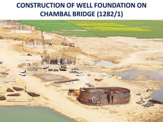
- 1. CONSTRUCTION OF WELL FOUNDATION ON CHAMBAL BRIDGE (1282/1)
- 2. This presentation cover the constructionof well foundation from Geotechnical investigation to Top plug of well foundation Step wise operation and activities as follow:- 1. Geotechnical Investigation 2. Survey work 3. Fabrication of cutting edge 4. Placing of cutting edge 5. Fabrication of brackets 6. Installation of brackets on cutting edge 7. Cutting, bending and fitting of plate 8. Reinforcement work of well curb 9. Casting of well curb 10. Sinking of well curb 11. Shuttering and Reinforcement work of well steining 12. Casting of well Steining 13. Sinking of well steining 14. Bottom plug 15. Sand filling 16. Top plug
- 3. Geotechnical Investigation Geotechnical investigationwork is carried out at every pier location of bridge to know the strata below the bed level to find Engineering propertiesof soil.
- 4. GEOTECHNICAL INVESTIGATION ON GROUND
- 5. FIELD SURVEY WORK • The survey work is carried out by taking reference from existing bridge and setting the TBM near to existing bridge . • The center line marking of proposed bridge using total station. • Control points and TBM are marked. • Center of each well foundationis marked by peg • OGL of proposed well foundation is taken.
- 6. VIEW OF EXISTING BRIDGES
- 7. SETTING OUT LOCATION AND LEVELING WORK •Location of proposed well foundation are located by Total Station with pre-define coordinates. • Original ground is level by leveling equipment.
- 8. FABRICATION OF CUTTING EDGE Cutting Edge is fabricated in fabrication yard consist of plate of 25mm and angle of 150*150*16 size and a bent plate of 12mm. Type of welding used are MAW and GMAW. Cutting edge is fabricated in 5 parts. 2 round part (D type) 2 straight 1 intermediate
- 9. PLACING OF CUTTING EDGE •The location is marked by coordinated system before placing of cuttingedge . •Wooden blocks are provided on level ground. • Cuttingedge is placed with the help of mobile crane (hydra)on wooden block. • After placing on wooden blockit is tie by temporaryarrangement by channels. • After fixingto exact location welding is done on joint of prefabricatedpart (5 parts)of cuttingedge.
- 11. FABRICATION OF BRACKETS • Angle of size75 mmX75 mmX8 mm are cut to required length. • Assembling of angle is done as per drawing. •Welding is done on joint.. •After welding dye penetration test is conduct. •Final Dimension is checked then it is transferred to site for fixing with cutting edge .
- 12. INSATALATION OF BRACKET ON CUTTING EDGE • Prefabricated brackets of angle size 75*75*8 areinstalled on cutting edge •After installation welding is done at joint of cutting edge and brackets. • Alignment and verticality of brackets is checked at every stage. • Spacing is also checked at every stage.
- 13. CUTTING BENDING AND FIXING OF SKIN PLATE • Cutting of plate done on level ground as per requirement . • it is then bend in bending machine to required angle . • Then it is transfer to site where it is fixed on cutting edge and bracket assembly with the help of crane •Welding is done on joint of plated by making suitable groove.
- 15. TESTING ON WELDING • Welding joint is clear by wire brush to removeSlug and dirt. • Cleaner is applied on welding joint . •After cleaner penetrator is applied. • After penetration of penetrator in welding Developer is applied . • After application of developer pin holes are detected if any and rectification is done the same.
- 16. REINFORCEMENT FIXING WORK IN WELL CURB • All the steel bars arecut to required cutting length • Hoop bars are bend in required Diameter. • Vertical bars threaded at one end to tie it with cutting edge as per drawing • Initially stirrup arefixed in fabricated well curb at required spacing . • Then Hoop reinforcementareplaced. • Link bars arebind with hoop reinforcement. • Then verticals are fixed at required spacing
- 17. CASTING OF WELL CURB • Casting of well curb done by M35 gradeof concrete • Concrete is transported fromRMC batching plant to site by transitmixer • concrete fromtransitmixer is pumped through concretepump to pouring location. •Beforepouring slump cone test performin order to check the workability of concrete • Concrete laid in layer of 300mm thickness. • Concrete compacted through needle vibrator.
- 18. SINKING OF WELL CURB • After casting of well curb sinking operation is proceed to sink the well curb below bed level. • Sinking is done by Grabing method with dredging soil inside dredge hole . the help of crane. •Regular sump, tilt and Shift is checked to maintain the stability of well.
- 19. SHUTTERING OF WELL STEINING • Shuttering plate is prepared by cleaning dust and stick material by wirebrush. • Shuttering oil is applied on shuttering plate • Joints are closed by foam. • Plates are fixed on well curb in required dimensions • Alignment is check after fixing of plate . • After checking the dimension and alignment plate are tied by nut bolt system • Wire ropes are tied around the outer Shuttering . • Inner D is fixed by Channel assembly • To maintained the thickness of well steining channels are in between inner and outer shuttering plates .
- 20. REINFOREMENT WORK OF WELL STEINING • Reinforcementbars are cut to required cut length. • Vertical bars arethreaded for fixing the mechanical splices for lapping purpose. • Inner and outer hoop reinforcement are fixed with vertical bars. • Tie bars are fixed with inner and outer hoop reinforcementas per drawing.
- 21. CASTING OF WELL STEINING • Casting of well steining done by M25 gradeof concrete • Concrete is transported fromRMC batching plant to site by transitmixer • concrete fromtransitmixer is pumped through concretepump to pouring location. •Beforepouring slump cone test performin order to check the workability of concrete • Concrete laid in layer of 400 mm thickness. • Concrete compacted through needle vibrator.
- 22. CURING OF WELL STEINING • After casting of well steining deshuttering operation processed • Then Curing is done by wrapped the hassion cloth
- 23. SINKING OF WELL STEINING • After casting of well steining sinking operation is proceed to sink the well below bed level. • Beforestart of sinking gauge marking is done on all 4 side of well • Sinking is done by Grabbing method with the help of cranefromdredged hole . •Regular sump, tilt and Shift is checked to maintain the stability of well. • If tilt and shift is out of limit then rectification is also operated .
- 24. COORECTION OF TILT AND SHIFT • Due to sinking operation sometime tilt and shift get out of permissible limt • Then correctivemeasuretaken on the well by providing suitable arrangement • In our project well P8 get rectified by apply kantledge load on well in one side and supportof prefabricated compositesection on another side by laid PCC below it. • By this method excess tilt get rectified .
- 25. BOTTOM PLUG OF WELL FOUNDATON • After sinking of well till required depth i.e. uptp founding level bottom plug is done upto a hieght of 300.mm abovethe top of well curb •In bottomplug grade of concrete used is M20 • For preparation of bottom plug the loose soil is dregdeout fromwell and sump is checked below FDL. • In bottom plug tremie pipe is used to pour the concretein each D • In bottom plug extra 10 % cement is used for under water concrete
- 26. SAND FILLING OF WELL FOUNDATION •After bottomplug next step is to fill the remaining dregde hole by sand . • Sand filled in well is free fromorganic material •Itshould be clean and washed • water to be poured to achieve full compaction
- 27. TOP PLUG •Top plug is done after sand filling in dregdehole . • Beforetop plug we haveto ensure that sand filled is fully saturated so full compaction can be achieved of sand. • Height of top plug is 500 mmabove sand filled • In top plug gradeof concreteis M20
- 28. THANKYOU Dilip Patidar Site Engineer /RVNL