The Role of FIDO in a Cyber Secure Netherlands: FIDO Paris Seminar.pptx
Advanced motion controls mc1xaz02
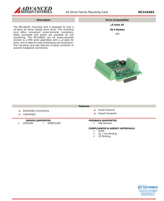
1. AZ Drive Family Mounting Card MC1XAZ02
Description
Drive Compatibility
The MC1XAZ02 mounting card is designed to host a μZ-style AZ series analog servo drive. This mounting card offers convenient screw-terminal connectors. Easily accessible test points are available for I/O monitoring. The MC1XAZ02 can be screw-mounted directly to a PCB when assembled with a μZ-style AZ drive, and is ideal for both prototyping and production. The mounting card also features a keyed connector to prevent misaligned connections.
μZ-style AZ
40 V Models
10A
Features
Detachable Connections
Lightweight
Small Footprint
Keyed Connector
DRIVES SUPPORTED
AZB10A4 ▪ AZBDC10A4
FEEDBACK SUPPORTED
Hall Sensors
COMPLIANCES & AGENCY APPROVALS
RoHS
UL / cUL Pending
CE Pending
ELECTROMATE
Toll Free Phone (877) SERVO98
Toll Free Fax (877) SERV099
www.electromate.com
sales@electromate.com
Sold & Serviced By:
2. AZ Drive Family Mounting Card MC1XAZ02
SPECIFICATIONS
Mechanical Specifications
Description
Units
Value
Agency Approvals
-
RoHS, UL / cUL Pending, CE Pending
Size (H x W x D) (mounting card only)
mm (in)
38.1 x 38.1 x 16.2 (1.5 x 1.5 x 0.64)
Size (H x W x D) (with drive installed)
mm (in)
38.1 x 38.1 x 23.6 (1.5 x 1.5 x 0.93)
Weight (mounting card only)
g (oz)
11.3 (0.4)
Bus Capacitance
μF
33
P4 Connector
-
12-port, 1.27 mm spaced header, vertical mount (pin 7 keyed)
P5 Connector
-
12-port, 1.27 mm spaced header, vertical mount
P10 Connector
-
6-port, 2.54 mm spaced fixed screw terminals
P11 Connector
-
12-port, 2.54 mm spaced fixed screw terminals
Information on Approvals and Compliances
RoHS (Reduction of Hazardous Substances) is intended to prevent hazardous substances such as lead from being manufactured in electrical and electronic equipment.
ELECTROMATE
Toll Free Phone (877) SERVO98
Toll Free Fax (877) SERV099
www.electromate.com
sales@electromate.com
Sold & Serviced By:
3. AZ Drive Family Mounting Card MC1XAZ02
PIN FUNCTIONS
P4 – Drive Mounting Power / Motor Connector
12-port vertical header for drive insertion – direct connection to the drive. Pin 7 keyed to avoid incorrect drive orientation. For pin functions refer to the drive datasheet.
P5 – Drive Mounting Signal Connector
12-port vertical header for drive insertion – direct connection to the drive. For pin functions refer to the drive datasheet.
P10 – Power / Motor Connector
Pin
Name
Description / Notes
I/O
1
MOTOR A
Motor Phase Outputs. Current output distributed equally across 2 pins per motor phase, 3A continuous current carrying capacity per pin. For single phase (brushed) motors, set DIP Switch SW1 to ON and use only Motor A and Motor B.
O
2
MOTOR B
O
3
MOTOR C
O
4
PWR GND
Power Ground (Common With Signal Ground). 3A Continuous Current Rating Per Pin
GND
5
HV IN
DC Power Input. 3A Continuous Current Rating Per Pin. Requires a minimum of 47 μF external capacitance between HV IN and PWR GND pins.
I
6
RESERVED
Reserved
-
P11 – I/O Connector
Pin
Name
Description
I/O
1
-REF IN
Differential Reference Input (±10 V Operating Range, ±15 V Maximum Input)
I
2
+REF IN
Differential Reference Input (±10 V Operating Range, ±15 V Maximum Input)
I
3
SIGNAL GND
Signal Ground (Common With Power Ground).
GND
4
FAULT OUT
TTL level (+5 V) output becomes high when power devices are disabled due to at least one of the following conditions: inhibit, invalid Hall state, output short circuit, over voltage, over temperature, power-up reset.
O
5
INHIBIT IN
TTL level (+5 V) inhibit/enable input. Leave open to enable drive. Pull to ground to inhibit drive. Inhibit turns off all power devices.
I
6
CURRENT MONITOR
Current Monitor. Analog output signal proportional to the actual current output. Scaling is 2 A/V. Measure relative to signal ground.
O
7
HALL 3
Single-ended Hall/Commutation Sensor Inputs (+5 V logic level). For single phase (brushed) motors, set DIP Switch SW1 to ON and leave all Hall signals open.
I
8
HALL 2
I
9
HALL 1
I
10
+V HALL OUT
Low Power Supply For Hall Sensors (+5 V @ 30 mA). Referenced to signal ground. Short circuit protected.
O
11
SIGNAL GND
Signal Ground (Common With Power Ground).
GND
12
RESERVED
Reserved
-
HARDWARE NOTES
DIP Switch Settings
When set to the ON position, DIP Switch SW1 internally shorts Hall 2 to ground for use with single phase (brushed) motors. Note that in this configuration, all Hall signal pins should be left open, and only motor phase outputs A and B should be used. Default switch setting is OFF (three phase / brushless motors).
DIP Switches SW2, SW3, SW4 are reserved.
ELECTROMATE
Toll Free Phone (877) SERVO98
Toll Free Fax (877) SERV099
www.electromate.com
sales@electromate.com
Sold & Serviced By:
4. AZ Drive Family Mounting Card MC1XAZ02
MECHANICAL INFORMATION
P4 – Drive Mounting Power / Motor Connector
Connector Information
12-port, 1.27 mm spaced header, vertical mount
Mating Connector
No mating connector required. Mate directly to drive.
P5 – Drive Mounting Signal Connector
Connector Information
12-port, 1.27 mm spaced header, vertical mount
Mating Connector
No mating connector required. Mate directly to drive.
P10 – Power / Motor Connector
Connector Information
6-port, 2.54 mm spaced fixed screw terminal
Mating Connector
Details
Not Applicable
Included with Drive
Not Applicable
1MOTOR A2MOTOR B3MOTOR C4PWR GND5HV IN6RESERVED
P11 – I/O Connector
Connector Information
12-port, 2.54 mm spaced fixed screw terminal
Mating Connector
Details
Not Applicable
Included with Drive
Not Applicable
12RESERVED11SIGNAL GND10+V HALL OUT9HALL 17HALL 38HALL 23SIGNAL GND2+REF IN1-REF IN4FAULT OUT5INHIBIT IN6CURRENT MONITOR
ELECTROMATE
Toll Free Phone (877) SERVO98
Toll Free Fax (877) SERV099
www.electromate.com
sales@electromate.com
Sold & Serviced By:
5. AZ Drive Family Mounting Card MC1XAZ02
MOUNTING DIMENSIONS
ELECTROMATE
Toll Free Phone (877) SERVO98
Toll Free Fax (877) SERV099
www.electromate.com
sales@electromate.com
Sold & Serviced By:
6. AZ Drive Family Mounting Card MC1XAZ02
PART NUMBERING INFORMATION
XDrive IndicatorIndicates the drive type(s) compatible with the mounting cardAxisNumber of axis supportedProduct TypeMC indicates mounting cardSeriesMounting card seriesMC1AZ02
All analog servo drive accessories listed in the selection tables of the website are readily available, standard product offerings. However, additional features and/or options are available for select drives and other possibilities can be made available for OEMs with sufficient volume requests. Feel free to contact Applications Engineering for further information and details.
All specifications in this document are subject to change without written notice. Actual product may differ from pictures provided in this document.
ELECTROMATE
Toll Free Phone (877) SERVO98
Toll Free Fax (877) SERV099
www.electromate.com
sales@electromate.com
Sold & Serviced By: