Mastering MySQL Database Architecture: Deep Dive into MySQL Shell and MySQL R...
Iai rcs2 ss8_r_specsheet
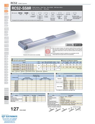
1. RCS2 ROBO Cylinder
RCS2-SS8R ROBO Cylinder Slider Type 80mm Width 200V Servo Motor
See Options below
* Be sure to specify which
side the motor is to be
mounted (ML/MR).
(1) When the stroke increases, the maximum speed will drop to prevent the
ball screw from reaching the critical rotational speed. Use the actuator
specification table below to check the maximum speed at the stroke you
desire.
(2) The load capacity is based on operation at an acceleration of 0.3G.
These values are the upper limits for the acceleration.
100: 100W Servo
motor
150: 150W Servo
motor
Motor
Output
O I N
Max. Load Capacity Rated
Lead
(mm) Horizontal (kg) Vertical (kg)
I : Incremental
A : Absolute
Model Stroke
20
30
6
128
Encoder & Stroke List 4 Cable List
Type Cable Symbol Standard Price
Standard
Special Lengths
Robot Cable
P (1m)
S (3m)
M (5m)
X06 (6m) ~ X10 (10m)
X11 (11m) ~ X15 (15m)
X16 (16m) ~ X20 (20m)
R01 (1m) ~ R03 (3m)
R04 (4m) ~ R05 (5m)
R06 (6m) ~ R10 (10m)
R11 (11m) ~ R15 (15m)
R16 (16m) ~ R20 (20m)
—
—
—
—
—
—
—
—
—
—
—
* For cables for maintenance, see page A-39.
Standard Price
1 Encoder Type
5 Option List Actuator Specifications
Item Description
Drive System
Positioning Repeatability
Lost Motion
Base
Allowable Static Moment
Allowable Dynamic Moment (*)
Overhang Load Length
Ambient Operating Temp./Humidity
Directions of Allowable Load Moments Overhang Load Length
L
L
Ma Mb Mc Ma Mc
Actuator Specifications
■ Lead and Load Capacity ■ Stroke and Maximum Speed
Legend 1 Encoder 2 Stroke 3 Compatible controller 4 Cable length 5 Options
Thrust (N)
(mm)
RCS2-SS8R- 1 -100-20- 2 - 3 - 4 - 5
RCS2-SS8R- 1 -100-10- 2 - 3 - 4 - 5
RCS2-SS8R- 1 -150-20- 2 - 3 - 4 - 5
RCS2-SS8R- 1 -150-10- 2 - 3 - 4 - 5
100
150
20
10
10
20
40
60
4
8
12
84.9
169
256
50 ~ 1000
(50mm
increments)
(Unit: mm/s)
Stroke
Lead
50 ~ 600
(50mm
increments)
~ 700
(mm)
~ 800
(mm)
~ 900
(mm)
~ 1000
(mm)
1000 960 765 625 515
500 480 380 310 255
20
10
-
-
-
-
-
-
-
-
-
-
-
-
-
-
-
-
-
-
-
-
-
-
-
-
-
-
-
-
-
-
—
—
—
—
—
—
—
—
—
—
50/100
150/200
250/300
350/400
450/500
550/600
650/700
750/800
850/900
950/1000
Technical
References P. A-5
Name Option Code See Page Standard Price
B
NM
ML
MR
SR
Brake
Reversed-home
Left-Mounted Motor (Standard)
Right-Mounted Motor
Slider Roller
Pictured: Left-mounted motor model (ML).
→A-25
→A-33
→A-33
→A-33
→A-36
—
—
—
—
—
Ball screw ø16mm C10 grade
±0.02mm
0.1mm or less
Material: Special alloy steel
Ma: 198.9N∙m Mb: 198.9N∙m Mc: 416.7N∙m
Ma: 36.3N∙m Mb: 36.3N∙m Mc: 77.4N∙m
Ma direction: 450mm or less Mb∙Mc direction: 450mm or less
0~40°C, 85% RH or less (Non-condensing)
(*) Based on 5,000km travel life.
Incremental
Motor power output
Absolute
Motor power output
100W 150W 100W 150W
2 Stroke (mm)
Side Mounted Motor Steel Base
* See page Pre-35 for explanation of each code that makes up the configuration name.
T1: XSEL-J/K
T2: SCON
SSEL
XSEL-P/Q
N : None
P : 1m
S : 3m
M : 5m
X □□ : Custom Length
R □□ : Robot Cable
50: 50mm
〜
1000:1000mm
(50mm pitch
increments)
20 : 20mm
10 : 10mm
■ Configuration: RCS2 SS8R
Series Type Encoder Motor Lead Stroke Compatible Controllers Cable Length Option
127 RCS2-SS8R
Slider
Type
Mini
Standard
Controllers
Integrated
Rod
Type
Mini
Standard
Controllers
Integrated
Table/Arm
/Flat Type
Mini
Standard
Gripper/
Rotary Type
Linear Servo
Type
Cleanroom
Type
Splash-Proof
Controllers
PMEC
/AMEC
PSEP
/ASEP
ROBO
NET
ERC2
PCON
ACON
SCON
PSEL
ASEL
SSEL
XSEL
Pulse Motor
Servo Motor
(24V)
Servo Motor
(200V)
Linear
Servo Motor
P
T
Notes on
Selection
Sold & Serviced By:
ELECTROMATE
Toll Free Phone (877) SERVO98
Toll Free Fax (877) SERV099
www.electromate.com
sales@electromate.com
2. CAD drawings can be
downloaded from IAI website. www.intelligentactuator.com
* The reference surface is the same as the SS8C type.
(See P110)
*1 The motor-encoder cable is connected here.
See page A-39 for details on cables.
* The bend radius R of the cable is the same as other models.
ME SE
70
55
90
4-ø5H7
depth 6 from
bottom of base
Oblong hole depth
from bottom of base 6
3 Compatible Controllers
The RCS2 series actuators can operate with the controllers below. Select the controller according to your usage.
RCS2 ROBO Cylinder
Home ME *2
Name External View Description Max. Positioning Points Input Voltage Power Model Supply Capacity Standard Price See Page
Positioner Mode
Pulse Train Input
Control Type
Program Control
1-6 Axis Type
SCON-C-1001-NP-2-2
SCON-C-1501-NP-2-2 →P547
SSEL-C-1-1001-NP-2-2
SSEL-C-1-150-NP1-2-2
XSEL-3-1-1001-N1-EEE-2-4
XSEL-3-1-1501-N1-EEE-2-4
Solenoid Valve
Mode
Positioning is
possible for up to
512 points
512 points
Single-Phase AC
100V
Single-Phase AC
200V
3-Phase AC
200V
(XSEL-P/Q only)
360VA max.
* When
operating a
150W single-axis
model
Operable with
same controls as
solenoid valve.
7 points
Dedicated to serial
communication
64 points
Dedicated to
Pulse Train Input
(−)
Programmed
operation is possible
Can operate
up to 2 axes
Programmed
operation is possible
Can operate
up to 6 axes
20000 points
20000 points
→P577
→P587
—
—
—
Serial
Communication
Type
Program Control
1-2 Axis Type
* For SSEL and XSEL, only applicable to the single-axis model.
* 1 is a placeholder for the encoder type (I: incremental, A: absolute).
* 2 is a placeholder for the power supply voltage (1: 100V, 2: single-phase 200V, 3: 3-phase 200V).
* 3 is a placeholder for the XSEL type name (J, K, P, or Q).
* 4 is a placeholder for the power supply voltage (1: 100V, 2: single-phase 200V, 3: 3-phase 200V).
Dimensions
17 30 C 170 30 6
5 5
8
A
29
0.5 61 4
145.5
1
34
60
80
43
70
80
0.5
59
34
26.5 16.5
Dimensions of the Brake Section
149 35
Cable joint
connector *1
2-ø8H7 depth 10
45 15 4-M8 depth 10
34
56
15
7.5
45
7.5 75
5 +0.012 0
6
Details of oblong hole
N×100 P F N×100 P
E-M8 depth 10
15
100 (reamer hole pitch)
15
D (reamer hole pitch) 100 (reamer hole pitch)
B
45
50 (reamer and oblong hole pitch)
* The offset reference position for the moment Ma is the same as the SS8C type. (See P110)
* Note that in order to change the home orientation, arrangements must be made to send in the product to IAI.
* For the reversed-home model, the dimensions (distance from the ME to home) on the motor-side and that on the
opposite side are flipped.
*2 When homing, the slider
moves to the ME;
therefore, please watch
for any interference with
the surrounding objects.
SE: Stroke end
ME: Mechanical end
* Adding a brake increases the
actuator's overall length by 26mm
and its weight by 0.5kg.
Stroke 100 200 300 400 500 600 700 800 900 1000
A
B
C
D
E
F
N
Weight (kg)
390
330
100
100
8
100
1
7.2
50
340
280
50
50
8
50
1
6.7
490
430
200
200
10
0
2
8.2
150
440
380
150
150
8
150
1
7.7
590
530
300
300
12
100
2
9.2
250
540
480
250
250
12
50
2
8.7
690
630
400
400
14
0
3
10.2
350
640
580
350
350
12
150
2
9.7
790
730
500
500
16
100
3
11.2
450
740
680
450
450
16
50
3
10.7
890
830
600
600
18
0
4
12.2
550
840
780
550
550
16
150
3
11.7
990
930
700
700
20
100
4
13.2
650
940
880
650
650
20
50
4
12.7
1090
1030
800
800
22
0
5
14.2
750
1040
980
750
750
20
150
4
13.7
1190
1130
900
900
24
100
5
15.2
850
1140
1080
850
850
24
50
5
14.7
1290
1230
1000
1000
26
0
6
16.2
950
1240
1180
950
950
24
150
5
15.7
■ Dimensions/Weight by Stroke
For Special Orders P. A-9
RCS2-SS8R 128
Slider
Type
Mini
Standard
Controllers
Integrated
Rod
Type
Mini
Standard
Controllers
Integrated
Table/Arm
/Flat Type
Mini
Standard
Gripper/
Rotary Type
Linear Servo
Type
Cleanroom
Type
Splash-Proof
Controllers
PMEC
/AMEC
PSEP
/ASEP
ROBO
NET
ERC2
PCON
ACON
SCON
PSEL
ASEL
SSEL
XSEL
Pulse Motor
Servo Motor
(24V)
Servo Motor
(200V)
Linear
Servo Motor
Sold & Serviced By:
ELECTROMATE
Toll Free Phone (877) SERVO98
Toll Free Fax (877) SERV099
www.electromate.com
sales@electromate.com