SlideShare una empresa de Scribd logo
1 de 15
Descargar para leer sin conexión
1
Down-Hole Gas Separator Performance Simulation
Software
J. N. McCoy, Ken Skinner and O. Lynn Rowlan, Echometer Company
Kyle Marshall, Capsher Technology
Tony Podio
Abstract
The performance of down hole gas separators is simulated in software. Different production rates, different
sizes of separators, different SPM and different gas bubble rise velocities are simulated to show the
performance of different separators and different well conditions. This simulation software is a great aid in
educating personnel in the operation, performance, selection and proper design of gas separators.
Knowledge and use of this software will help operators increase pump fillage and total production and also
reduce operating expenses.
Definition of Terms and Basic Operation of Down hole Gas Separators
A frequent reason for inefficient down-hole pump operation is incomplete liquid fillage caused by gas
interference especially when the pump intake is set above the perforations that are producing gas and
liquid. A common solution of this problem is to install, at the bottom of the tubing, a down hole gas
separator (often called a “gas anchor”) just below the pump intake or to configure the completion so that
the pump intake is located below the gas entry point into the wellbore. These designs take advantage of
natural separation due to gravity segregation of the gas and liquid phases to maximize the volume of liquid
delivered to the pump intake.
Figure 1 is a simplified schematic of what is defined as a “tubing conveyed down hole gas separator”
installed above the producing formation and showing the fluids (oil, water and gas) entering from the
perforations and flowing upwards in the wellbore annulus to the separator openings. The majority of the
produced gas flows past the separator inlet openings and continues up through the casing-tubing annulus to
the surface1
while the liquid and a smaller amount of gas enter the separator inner annulus. At the top of the
separator outer barrel or mud anchor are several openings through which the produced liquid and some gas
enter the separator and also through which the separated gas can return to the wellbore. The dip tube is a
small diameter tube inside the separator outer barrel that directs the produced fluid to the pump intake and
into the pump barrel. Inside the separator annulus there is a gas/liquid mixture with the liquid flowing
down towards the dip tube suction. The less dense fluid in the mixture, i.e. the gas, has an upward velocity
relative to the denser liquid. Depending on its size, each gas bubble in the separator annulus (annular area
between the separator outer barrel and the dip tube) has an upward velocity relative to the liquid, known as
the slip velocity. The motion and position of the gas bubbles depend on the difference between the
downward liquid velocity and upwards bubble slip velocity. For a given liquid flow rate and separator
design, small bubbles (less than 1/16 of an inch) may be dragged by the liquid into the dip tube while larger
gas bubbles (greater than 1/4 inch) may flow upwards and out through the separator ports, ultimately
venting out through the casing-tubing annulus. Therefore, the slower the liquid is moving down the smaller
the volume of gas that is dragged by the liquid into the dip tube. Consequently the pump liquid fillage
would be near 100%.
2
In this gravity separation system, the efficiency of separation of gas from liquid is controlled by the
downward liquid velocity in the annulus between the separator outer barrel and the inner dip tube. The
liquid velocity is controlled by two variables:
1. The actual pump displacement rate. For a rod pump this rate is determined by the plunger area, the
plunger velocity and the plunger leakage.
2. The annular area between the internal diameter (ID) of the separator outer barrel and the outer
diameter (OD) of the dip tube.
Field experience and laboratory studies1-10
have shown that when the separator annular liquid velocity is
less than or equal to about 6 inches per second the majority of the large (greater than1/4 inch) gas bubbles
are able to overcome the drag forces caused by the liquid’s downward motion and flow upwards so that
mainly liquid reaches the entry to the dip tube. As the downward liquid velocity increases, above this 6
inch/second limit, a larger volume of gas is dragged down the separator annulus and into the pump. The
pump’s liquid fillage decreases accordingly. This concept is clearly illustrated in Figure 2 where three
video snapshots are displayed for different downward liquid velocity inside the annulus of a separator (built
with clear acrylic pipe 2.75 inch ID and with a 1.5 inch OD dip tube) inside clear 6 inch ID casing. When
the video was taken the gas flow rate in the casing annulus was constant at about 96 MSCF/D. Liquid rate
through the separator was increased gradually from zero to 420 Bbl/day. When the liquid rate is 243
Bbl/day its velocity in the separator annulus is 5 inch/second and only very small gas bubbles are seen
being dragged down and into the dip tube. When the rate is increased to 275 Bbl/D the liquid velocity is
about 6 inch/sec and a high concentration of bubbles has formed in the separator annuls above the entrance
to the dip tube. These bubbles are in equilibrium (they do not rise or move downwards) while liquid and
smaller bubbles are flowing down and into the dip tube.
(NOTE: Copies of the original videos can be downloaded for free from the following web site:
http://www.utexas.edu/ce/petex//aids/pubs/beamlift/toolbox/#downholeseparator and also will be handed
out at the SWPSC with the simulation software.)
For a pumped well the downward liquid velocity in the separator annulus is determined by the ratio of the
actual pump displacement rate to the separator annular area. In practical terms, a pump rate of 53.4 Bbl/day
flowing in a conduit that has a cross sectional area of 1 square inch results in an average liquid velocity of 6
inches per second. For a given outer-barrel/dip-tube diameter combination, a liquid flow rate limit that
results in efficient gas/liquid separation can be computed knowing the annular area. For example, a
pumping well completed with 5-1/2 inch casing and 2-7/8 tubing with a separator dip tube of 1-1/4 inch
outer diameter set inside a 2-7/8 perforated sub and separator outer barrel would have an annular area of
approximately 3.45 square inches which would result in an efficient liquid separation capacity of 184
bbl/day. Table 1 lists the capacities of some of the most common practical separator configurations
assuming that their performance is not affected by other variables such as excessive casing gas flow rate or
the installation tools causing restricted flow into the pump such as small strainer nipples or long dip tubes.
Special Pumps
Whenever the pump intake is set above the perforations in a well producing significant free gas the down
hole gas separator is the principal component in determining the pump liquid fillage. For normal pump
operation the percentage of liquid present in the pump barrel at the top of the upstroke cannot be larger than
the percentage of liquid that the down hole gas separator delivers at the pump intake. One exception is
when special pumps with a large barrel/plunger clearance or pumps with variable slippage barrels are used
to fill the pump with additional liquid flowing into the barrel from the bottom of the tubing rather than from
below the standing valve. Since liquid flows into the pump barrel from the tubing, the production rate from
the formation is reduced. Such specialty pumps are not included in the following discussion.
Separator Pump Fillage Factor
Based on the previous description of the gravity mechanism at work in the gas separator and the operation
of the pump, we can define a Separator Pump Fillage Factor that represents the % of liquid that a given
separator with a specific design delivers to the pump intake at different displacement rates.
3
Given a pumping well where the casing annulus gas flow rate is significant but results in a gas superficial
velocity less than 5 ft per second, then the Separator Pump Fillage Factor is primarily a function of only
the liquid flow rate through the separator and thus of the actual pump displacement rate. For a given
separator design, the pump fillage factor is a value close to 100% only for very low pumping rates where
the liquid velocity is such that just very small gas bubbles reach the entrance of the dip tube. Such low rates
generally are not economical and are not used in practice. As the pumping rate increases the Pump Fillage
Factor decreases as shown by numerous controlled laboratory tests reported in reference 2.
The general trend of the Separator Pump Fillage Factor is illustrated in Figure 3 for three of the separator
designs listed in Table 1. The Pump Fillage Factor decreases slowly from 100% as the liquid rate increases.
Then at some point, near the liquid rate that corresponds to the 6 inch/per second liquid velocity limit, it
begins to drop rapidly .This flow rate is indicated on the horizontal axis by the colored dot markers and
corresponds to the point where the Fillage Factor begins to drop below 95-97%. When the liquid flow rate
exceeds this limit, the shape of the curve past this point varies slightly depending of factors such as number
and shape of the openings into the separator and the flow rate of the gas flowing in the casing-tubing
annulus. These effects are minor, as described in detail in Reference 2, compared to the effect of the
separator annular flow area in determining the separator capacity.
For evaluation of a specific separator design or for selection of a standard off-the-shelf separator, the
important quantity is the flow rate at which the separator efficiency begins to deteriorate. The actual shape
of the pump fillage factor curve for rates greater than the limit does not impact on the decision about the
performance of a specific separator since the objective is to design or select a separator that delivers better
than 95% liquid to the pump intake.
For a given combination of plunger pump and gas separator the net liquid pump displacement can be
computed as the product of the net plunger displacement times the Separator Pump Fillage Factor as
expressed in the following relation:
Where:
PumpDisplacement is the net pump flow rate in bbl/day.
PlungerDisplacement is the plunger flow rate in bbl/day, corresponding to the plunger travel, plunger
diameter and pumping speed.
Separator Pump Fillage Factor is a number that depends on the specific separator design and the plunger
flow rate.
This relation assumes that the pump-separator system does not suffer from other inefficiencies that would
reduce the pump liquid fillage such as using an undersized standing valve, a small diameter strainer nipple,
a screen strainer, an excessively long small diameter dip tube, or the presence of scale or paraffin that
partially obstructs the intake and restricts inflow of liquid to the pump barrel.
The software described in this paper has the objective of assisting the operator in the selection of a specific
down hole gas separator by computing the maximum pumping rate that keeps the pump barrel at a liquid
fillage greater than 95% and displaying a quantitative animation of the operation of the separator. The best
suited separator is one that results in the greatest flow rate for a fillage factor of 95%.
4
Simulation and Visualization of Down-Hole Gas Separator Operation
Although the basic principles of down hole gas separation described in the previous section are relatively
simple, the interaction between the plunger pump operation and the separator are somewhat difficult to
visualize since it involves dynamic effects of multi-phase flow. The flow of the liquid and the gas within
the separator is intermittent and dependent on the motion and velocity of the pump plunger.
Referring to Figure 1, during the plunger upstroke fluid is removed from the lower portion of the gas
separator through the dip tube and is delivered to the pump intake. During the same time, liquid and gas
flow from the casing annulus through the separator openings into the separator annulus. Whenever the
casing annular gas flow rate is significant it causes lots of turbulence and creates a mixture of liquid with
gas broken up into bubbles of various sizes. The amount of gas that enters the separator with the liquid is
dependent on the pumping rate and the percentage of gas and liquid that are present in the casing annulus.
This percentage of gas and liquid can be estimated easily by analyzing acoustic fluid level records that
include measurement of casing pressure buildup rate.
As the liquid inside the separator is moving downwards, it drags a certain amount of gas bubbles towards
the bottom of the separator at a net velocity that is equal to the liquid velocity minus the gas bubble slip
velocity. For example, the duration of the plunger upstroke for a pumping speed of 10 strokes per minute is
approximately 3 seconds (assuming a conventional beam pump). Assuming that for the current pumping
speed the liquid is moving down at an average of about 6 inches per second it would travel a distance of 18
inches from the bottom of the separator openings by the end of the plunger upstroke. Small gas bubbles that
have an upwards slip velocity of only 2 inches per second will have an average downwards net velocity of
6-2=4 inches/second and will be dragged down a distance of 12 inches from the bottom of the openings by
the end of the plunger upstroke. Large bubbles that have a slip velocity greater than 6 inches per second
inches per second would not be dragged down towards the bottom of the separator annulus.
During the approximate 3 second duration of the plunger down stroke, the flow of liquid into the dip tube
and the pump stops and the downward velocity of the liquid in the separator annulus becomes zero. The
small gas bubbles will rise at a rate of 2 inches per second (the liquid is at rest) to a distance of 6 inches
from their current position. At that time they still will be located inside the separator annulus at 6 inches
below the bottom of the separator openings. During the next plunger upstroke they will be dragged further
down another 12 inches and reach a point 24 inches from the openings. This process will continue until the
small bubbles eventually will reach the entrance to the dip tube (regardless of the length of the dip tube)
and will flow into the pump. Those bubbles that have a slip velocity greater than 6 inches per second will
not be dragged below the bottom of the separator openings and will exit through the separator openings.
Most gas bubbles that are in the separator annulus below the bottom of the ports at the beginning of the
upstroke will eventually be drawn into the pump.
This model of the flow mechanism inside the separator annulus is much simplified since the velocity of the
pump plunger is not a constant but goes from zero to a maximum at about the middle of the upstroke and
then back to zero at the top of the stroke. Also the flow into the pump barrel occurs only during the time
when the standing valve is open. The operation of the standing valve is controlled by the difference in
pressure between the pump barrel and the pump intake which does not necessarily occur from the
beginning to the end of the plunger upstroke. Figure 4 displays the detailed analysis of a dynamometer
record acquired in a pumping well where the pump liquid fillage was about 94%. The figure on the left
shows the actual instantaneous plunger velocity (green line) during one stroke for a rod pump operating at
about 7 strokes per minute. From inspection of the pump dynamometer card for this stroke, displayed at the
bottom right, we can see that the tubing is not anchored and the pump barrel is filled with liquid. Notice
that the plunger velocity starts at zero, increases slowly then speeds up (at point where the SV opens) then
peaks at about 55 inch/sec at about 3.1 seconds. The plunger then slows down as it reaches the top of the
stroke where the standing valve closes. Knowing the plunger area and the cross sectional area of the
separator annulus one can compute the instantaneous velocity of the liquid moving down inside the
separator. The corresponding value for this upstroke is plotted on the graph as the black curve. The liquid
velocity in the separator annulus is plotted as a negative value indicating liquid is moving down. The
velocity is zero until about 1.9 seconds when the standing valve opens, then reaches a maximum of about -
5
17 inches/second then back to zero when the standing valve closes at about 4.1 seconds. Therefore
downward flow of liquid in the separator annulus occurs only during (4.1-1.9) = 2.2 seconds out of the 8.6
seconds of the total stroke period. This means that the liquid in the separator annulus is practically
stationary during 6.4 seconds which is the time available for gas bubbles to slip upwards and out of the
separator. The simplified separator model discussed earlier considers that the liquid’s “quiet” time would
be one half of the stroke period, or only 4.3 seconds.
This illustrates the need to couple a realistic model of the plunger operation and the separator flow model in
order to correctly evaluate the liquid capacity of a specific separator design. However, for separator design
and comparison purposes it is sufficient to represent the plunger velocity function with an approximate but
realistic model that corresponds to the type of pumping unit used. (Note: a more accurate separator design
application could use the plunger velocity function that could be exported from the QRod program)
Figure 5 shows the generalized liquid inflow profile that is a default option in the simulation software
presented in this paper. It assumes that the pump is operated by a beam pump and that operation of the
standing valve follows a normal pattern so that downward liquid flow in the separator annulus occurs
during about 43% of the pumping period. The maximum flow rate corresponds to about 3.77 times the
average plunger displacement rate assuming the pump is full of liquid at the top of the pump stroke. The
trapezoidal shape is derived from studying the plunger movement observed in a large number of
dynamometer cards in wells producing at significant rates and with no gas interference. Future versions of
the application will include the ability to specify or import different plunger velocity profiles such as for
linear motion pumping units and progressing cavity pumps.
Gas Separator Simulation Application
To evaluate the performance of the separator it is necessary to simulate the operation of the combined
system consisting of the separator, the down-hole pump and the pumping unit, in conjunction with the
operating parameters. The characteristics of the system have to be defined by the user through input data
provided to the application.
The objectives of the application are:
 Provide to the user a tool to easily compare the probable performance of different designs
pumping system combinations and fluid properties.
 Present results in a simple and graphical format.
 Visualize the effect of modifying separator and pumping system parameters on the performance of
the gas separator.
 Facilitate data input and user interaction with software
Figure 6 present the display screen presented to the user for input of the simulation parameters. Data
shown are default values representing a system that is commonly used by most operators and include:
 Casing size
 Separator Type
 Separator outer barrel OD and ID (inches)
 Dip Tube OD and ID (inches)
 Dip Tube Length below separator inlet openings (inches)
 Gas Bubble Slip Velocity (inch/second
 Production rate (Bbl/day)
 Pumping speed in strokes per minute
To facilitate interaction with the application a number of preset separator types are included in the pull-
down menu so the user only has to choose from the following:
 Collar Size Separator (Echometer)
o 2 3/8 inch collar size separator
6
o 2 7/8 inch collar size separator
o 3.5 inch collar size separator
 Poor Boy Separator
o 2 3/8 inch poor boy with 8 foot dip tube and 4 ft perforated nipple.
o 2 7/8 inch poor boy with 8 foot dip tube and 4 ft perforated nipple.
 Custom Separator
o Dip tube length below separator inlet (default 4 ft)
o OD of gas separator outer barrel
o ID of gas separator outer barrel
o OD of dip tube
o ID of dip tube
The user can accept the preset values or input his particular design and operating conditions.
Once the pumping/separator system has been defined the simulation is executed by clicking on the large
green button on the top which starts pump operation and switches to the separator visualization and
animation screen shown in Figure 7 where the user can see observe in real time the distribution and flow of
the gas and liquid in the separator. In the figure, one can observe that when a particular separator is
operating near capacity, mostly liquid occupies the lower portion of the separator annulus and mostly gas is
in the upper part with a net gaseous/liquid interface at about 3/4 of the distance from the separator
openings to the entrance to the dip tube. This interface oscillates up and down as the plunger strokes but it
never reaches the bottom of the dip tube so that only a minimal volume of gas reaches the pump intake.
For this example this condition occurs at a pumping speed of about 7 SPM with a corresponding pump
displacement of 100 Bbl/day. From this screen the user can start and stop the pump and change the
pumping speed so as to observe the effect of SPM on the separator’s performance and the position of the
gas bubbles within the separator annulus. The liquid rate that corresponds to a particular condition is
displayed in real time and a warning message is shown when the gas breaks through into the bottom of the
dip tube and into the pump.
The simulation and visualization software lets the user make adjustments to the separator design in order to
develop the best arrangement for the particular well conditions. Returning to the input the separator
parameters can be easily modified and the new results observed in the animation screen.
The separator simulation application can also be valuable in training of personnel that are involved in
monitoring and optimizing the operation of pumping wells.
Field studies will be conducted with operators in specific areas to determine the recommended bubble slip
velocity to be used for wells in that area.
Following are the principal assumptions that have been considered in the development of the simulation:
 A gaseous fluid column exists above the pump and separator ports.
 The dip tube and standing valve are properly sized and installed for minimum pressure drop so gas
is not released from oil in the dip tube and in the pump intake standing valve flow path.
 The plunger does not leak excessively.
 The Production Rate that the operator enters is the actual production rate which would also be the
pump displacement assuming 100% pump fillage and minimum plunger leakage.
These conditions must be satisfied for the simulation to provide a reasonably accurate representation of the
operation of the separator.
The Down-Hole Gas Separator Simulation and Visualization is a free application for Windows OS that can
be downloaded from the Echometer web site www.echometer.com.
7
Down-Hole Gas Separator Design Recommendations
The following summary recalls some of the most important concepts about down hole gas separator design
that have been developed over numerous years of field experience and laboratory testing 1-9
.
 Maximize the size of the separator annular area to maximize the separator liquid capacity.
 Using a mud anchor with thin walls increases the size of the separator annular area. But efforts
should be made to ensure that the mud anchor walls have the necessary strength.
 For gravity-driven separators in low viscosity fluid applications, good gas-liquid separation occurs
when the superficial downward liquid velocity inside the separator is 6 in/second or less. The
separator pump fillage factor decreases rapidly when this liquid velocity is exceeded.
 Excessive gas velocity in the casing annulus reduces the separator performance since it prevents
liquid from entering the separator openings. The annular area between casing and separator should
be large enough so that gas velocity in the casing annulus is less than 10 ft/sec.
 A long dip tube can be detrimental. A 5.5 ft long dip tube is enough for efficient gas separation
for gravity-driven separators. The dip tube should extend about 4-5 feet below the separator inlet
openings.
 The inner diameter of the dip tube should be sufficient to minimize the overall pressure drop
through the separator.
 Under laboratory conditions2
, increasing the total area of the openings into the separator to over
65% of the separator outer barrel-dip tube annular area does not considerably improve the
separator efficiency.
 Multiple rows of opening are not necessary. Additional rows should only be considered if port
plugging is anticipated, based on the chemical evaluation of the fluids.
8
References
1) Robles, J. and A. L. Podio, “Effect of Free Gas and Downhole Gas Separation Efficiency on the
Volumetric Efficiency of Sucker Rod Pumps and Progressing Cavity Pumps,” Proceedings of the
43rd Annual Meeting of the SWPSC, 1996.
2) Bohorquez, R., Ananaba, V., Alabi, O., Podio, A. L., Lisigurski, O. and Guzman, M.: 2009,
“Laboratory Testing of Downhole Gas Separators”, SPE Production and Operations, Volume 24,
Number 4, pp.499-509.
3) Campbell, J. H., Brimhall, R.M., 1989. “An Engineering Approach to Gas Anchor Design,” SPE
Production Operations Symposium.
4) Clegg, J.D., “Another Look at Gas Anchors”. 1989, Southwestern Petroleum Short Course
Proceedings pp.293-307.
5) Guzman, M., 2005. “Downhole Gas Separator Performance in Sucker Rod Pumping System”,
M. S. Thesis, The University of Texas at Austin, Austin.
6) Lisigurski, O., 2004. “The Effect of Geometry on the Efficiency of Downhole Gas Separators”,
M. S. Thesis, The University of Texas at Austin, Austin.
7) McCoy, J.N., Podio, A.L., Lisigurski, O., Patterson, J., and Rowlan, L.: “A Laboratory Study with
Field Data of Downhole Gas Separators,” SPE 96619, Presented at the 2005 SPE Annual
Technical Conference held in Dallas, Texas, 9-12 October.
8) McCoy, J.N., Podio, A.L.: “Improved Downhole Gas Separator,” 1998, Presented at the Annual
Southwestern Petroleum Short Course.
9) Patterson, J.C., and Leonard, L.: “Gas Anchor Design Changes Used to Improve Gas Separation in
Coalbed Methane Operations in Wyoming,” 2003, Presented at the Annual Southwestern
Petroleum Short Course.
10) McCoy, J. N. et al. 2013: “Optimizing Downhole Packer-Type Separators”, 2013, Presented at the
Annual Southwestern Petroleum Short Course.
9
Table 1 – Efficient Operation Capacity of Typical Down-Hole Gas Separators
Separator Type
OD barrel,
inch
ID barrel,
inch
OD dip
tube,
inch
Annular Area
in2
Efficient
Operation
Capacity
Bbl/day
2-3/8 Poor Boy 2.375 1.990 1.350 1.76 94
2-3/8 Collar Size 3.000 2.750 1.350 4.57 244
2-7/8 Poor Boy 2.875 2.441 1.660 2.51 134
2-7/8 Collar Size 3.750 3.500 1.660 7.45 398
3-1/2 Poor Boy 3.500 2.990 1.900 4.18 223
3-1/2 Collar Size 4.500 4.260 1.900 11.34 606
10
Figures
Figure 1 – Schematic Diagram and Definition of Terms for a Tubing Conveyed Down Hole Gas
separator
1
.
Tubing Conveyed Downhole Gas Separator
Gravity separation of gas
and liquid is the governing
mechanism of down hole
gas separators.
Casing
Pump
Separator
Openings
Separator
Annulus
Outer barrel
Dip tube
Casing
Annulus
Flow from
Formation
Gas
Liquid
11
Figure 2 – Video Snap-shots of Gas Bubble Concentration
2
in Separator Annulus as a Function of
Downward Liquid Flow Rate for Annular Area of 5.15 in
2
Effect of Liquid Velocity
5 inch/sec
243 BPD
6 inch/sec
275 BPD
9 inch/sec
420 BPD
Separator Outer Barrel
Dip Tube
Casing
12
Figure 3 – Pump Fillage Factor as a Function of Plunger Displacement Rate for 3 Separator
Designs. (Colored markers on horizontal axis indicate individual separator capacities from Table 1)
`
60
70
80
90
100
110
0 100 200 300 400 500 600
PumpFillageFactor%
PlungerDisplacementRate,Bbl/day
Separator PumpFillage Factor vs. Plunger DisplacementRate for
Different SeparatorDesigns
2-3/8 poor boy w/1.32 OD dip tube 2-7/8 poor boy w/ 1.66 OD dip tube
2-7/8 Collar size w/ 1.66 OD dip tube
13
Figure 4 – Pump Plunger Velocity and Velocity of Liquid in Separator Annulus for Conventional
Beam Pump Operating at 6.95 Strokes per Minute.
Figure 5 – Generalized Liquid Inflow Profile for Separator Simulation
Plunger Velocity and Velocity of Liquid in the Separator
Annulus During One Pump Stroke
4.17 sec
SV Closes
1.8 sec
SV Opens
Pump Plunger
Velocity
Liquid Velocity
Inside Separator
20
Pump Plunger
Velocity
Liquid Velocity in
Separator Annulus
Separator Liquid Flow Rate Profile
Maximum Rate is 3.77 times Average
Profile selected from dynamometer
data on higher volume wells.
400
300
200
100
0
Time as % of stroke Period
Average Production Rate
SeparatorLiquidInflowProfile,percent
ofAverageRate
100
%
48%5 %
14
Figure 6 – Simulator Input Screen for Definition of Gas Separator Dimensions and
Pumping System and Fluid Properties.
15
Figure 7 – Separator operation simulation and visualization screen.
Pump Displacement = 100 Bbl/day
SPM = 6.95
Gas/Liquid Interface
5.5 17 #/ft
3.00
2.75
1.35
2-3/8 Collar Size Separator
42
1.084

Más contenido relacionado

La actualidad más candente

Problems faced in conrol valves ppt
Problems faced in conrol valves pptProblems faced in conrol valves ppt
Problems faced in conrol valves pptPrem Baboo
 
Production methods for Petroleum
 Production methods for Petroleum Production methods for Petroleum
Production methods for PetroleumWajid09
 
Sucker rod pumping short course!!! ~downhole diagnostic
Sucker rod pumping short course!!!   ~downhole diagnosticSucker rod pumping short course!!!   ~downhole diagnostic
Sucker rod pumping short course!!! ~downhole diagnosticenLightNme888
 
Petrobowl Well Testing Study Questions
Petrobowl  Well Testing Study QuestionsPetrobowl  Well Testing Study Questions
Petrobowl Well Testing Study QuestionsNya Parwon
 
Air Valve Basic Training
Air Valve Basic Training Air Valve Basic Training
Air Valve Basic Training guest65d195
 
Non mechanical valves
Non mechanical valvesNon mechanical valves
Non mechanical valvesRaju Gupta
 
Valvula masoneilan handbook for control valve sizing
Valvula masoneilan handbook for control valve sizingValvula masoneilan handbook for control valve sizing
Valvula masoneilan handbook for control valve sizingJupira Silva
 
01 General Control Valves Training.
01 General Control Valves Training.01 General Control Valves Training.
01 General Control Valves Training.SuryamshVikrama
 
Maintenance of distillation column asmita
Maintenance of distillation column asmitaMaintenance of distillation column asmita
Maintenance of distillation column asmitaAsmita Mishra
 
Production optimization using gas lift technique
Production optimization using gas lift techniqueProduction optimization using gas lift technique
Production optimization using gas lift techniqueJarjis Mohammed
 
Gas Absorption & Stripping in Chemical Engineering (Part 3/4)
Gas Absorption & Stripping in Chemical Engineering (Part 3/4)Gas Absorption & Stripping in Chemical Engineering (Part 3/4)
Gas Absorption & Stripping in Chemical Engineering (Part 3/4)Chemical Engineering Guy
 
Control valve presentation
Control valve presentationControl valve presentation
Control valve presentationPrem kumar
 
شیرهای کنترلی دوستارگان
شیرهای کنترلی دوستارگانشیرهای کنترلی دوستارگان
شیرهای کنترلی دوستارگانAkbar Doustaregan
 
Water and Waste Water Treatment - EN - 140716 - webreduced
Water and Waste Water Treatment - EN - 140716 - webreducedWater and Waste Water Treatment - EN - 140716 - webreduced
Water and Waste Water Treatment - EN - 140716 - webreducedTomas Eriksson
 
Flooding of a distillation column
Flooding of a distillation columnFlooding of a distillation column
Flooding of a distillation columnKarnav Rana
 

La actualidad más candente (20)

Problems faced in conrol valves ppt
Problems faced in conrol valves pptProblems faced in conrol valves ppt
Problems faced in conrol valves ppt
 
Production methods for Petroleum
 Production methods for Petroleum Production methods for Petroleum
Production methods for Petroleum
 
Sucker rod pumping short course!!! ~downhole diagnostic
Sucker rod pumping short course!!!   ~downhole diagnosticSucker rod pumping short course!!!   ~downhole diagnostic
Sucker rod pumping short course!!! ~downhole diagnostic
 
Low shear basics - 2017
Low shear basics - 2017Low shear basics - 2017
Low shear basics - 2017
 
Petrobowl Well Testing Study Questions
Petrobowl  Well Testing Study QuestionsPetrobowl  Well Testing Study Questions
Petrobowl Well Testing Study Questions
 
Control valve
Control valveControl valve
Control valve
 
Packed columns
Packed columnsPacked columns
Packed columns
 
Air Valve Basic Training
Air Valve Basic Training Air Valve Basic Training
Air Valve Basic Training
 
Non mechanical valves
Non mechanical valvesNon mechanical valves
Non mechanical valves
 
Valvula masoneilan handbook for control valve sizing
Valvula masoneilan handbook for control valve sizingValvula masoneilan handbook for control valve sizing
Valvula masoneilan handbook for control valve sizing
 
01 General Control Valves Training.
01 General Control Valves Training.01 General Control Valves Training.
01 General Control Valves Training.
 
Maintenance of distillation column asmita
Maintenance of distillation column asmitaMaintenance of distillation column asmita
Maintenance of distillation column asmita
 
Production optimization using gas lift technique
Production optimization using gas lift techniqueProduction optimization using gas lift technique
Production optimization using gas lift technique
 
Gas Absorption & Stripping in Chemical Engineering (Part 3/4)
Gas Absorption & Stripping in Chemical Engineering (Part 3/4)Gas Absorption & Stripping in Chemical Engineering (Part 3/4)
Gas Absorption & Stripping in Chemical Engineering (Part 3/4)
 
Control valve presentation
Control valve presentationControl valve presentation
Control valve presentation
 
شیرهای کنترلی دوستارگان
شیرهای کنترلی دوستارگانشیرهای کنترلی دوستارگان
شیرهای کنترلی دوستارگان
 
Control valve ppt
Control valve pptControl valve ppt
Control valve ppt
 
Water and Waste Water Treatment - EN - 140716 - webreduced
Water and Waste Water Treatment - EN - 140716 - webreducedWater and Waste Water Treatment - EN - 140716 - webreduced
Water and Waste Water Treatment - EN - 140716 - webreduced
 
Distillation.pdf
Distillation.pdfDistillation.pdf
Distillation.pdf
 
Flooding of a distillation column
Flooding of a distillation columnFlooding of a distillation column
Flooding of a distillation column
 

Destacado

Hop'Toys catalogue Noël 2016
Hop'Toys catalogue Noël 2016Hop'Toys catalogue Noël 2016
Hop'Toys catalogue Noël 2016Julien Servy
 
Aumento en las dietas de los legisladores: así votó cada uno
Aumento en las dietas de los legisladores: así votó cada unoAumento en las dietas de los legisladores: así votó cada uno
Aumento en las dietas de los legisladores: así votó cada unoPrimera Edición Diario
 
Shekru Deck Brief Introduction
Shekru Deck Brief IntroductionShekru Deck Brief Introduction
Shekru Deck Brief IntroductionBIBHISHAN BAGAL
 
Los materiales y las energía en la informática
Los materiales y las energía en la informáticaLos materiales y las energía en la informática
Los materiales y las energía en la informáticaedder43534523234342332
 
Отчёт о работе младшего абонемента за 2016 год
Отчёт о работе младшего абонемента за 2016 годОтчёт о работе младшего абонемента за 2016 год
Отчёт о работе младшего абонемента за 2016 годSvetlana Isakova
 
Historia del calculo
Historia del calculoHistoria del calculo
Historia del calculoAdrian Luna
 
Лечение сочетанных доброкачественных опухолей и гиперпластических процессов м...
Лечение сочетанных доброкачественных опухолей и гиперпластических процессов м...Лечение сочетанных доброкачественных опухолей и гиперпластических процессов м...
Лечение сочетанных доброкачественных опухолей и гиперпластических процессов м...Alexander Klimanov
 
06. cuestionario (sin respuestas) de hebreos 5 el llamamiento celestial
06.  cuestionario (sin respuestas) de hebreos 5 el llamamiento celestial06.  cuestionario (sin respuestas) de hebreos 5 el llamamiento celestial
06. cuestionario (sin respuestas) de hebreos 5 el llamamiento celestialYosef Sanchez
 
Srinivasa_Jonnalagadda_Resume
Srinivasa_Jonnalagadda_ResumeSrinivasa_Jonnalagadda_Resume
Srinivasa_Jonnalagadda_ResumeSrinivasa Pavan
 
Pseudomona aeruginosa
Pseudomona aeruginosaPseudomona aeruginosa
Pseudomona aeruginosaIrving Plaza
 

Destacado (14)

Hop'Toys catalogue Noël 2016
Hop'Toys catalogue Noël 2016Hop'Toys catalogue Noël 2016
Hop'Toys catalogue Noël 2016
 
Aumento en las dietas de los legisladores: así votó cada uno
Aumento en las dietas de los legisladores: así votó cada unoAumento en las dietas de los legisladores: así votó cada uno
Aumento en las dietas de los legisladores: así votó cada uno
 
Credentials
CredentialsCredentials
Credentials
 
Shekru Deck Brief Introduction
Shekru Deck Brief IntroductionShekru Deck Brief Introduction
Shekru Deck Brief Introduction
 
Los materiales y las energía en la informática
Los materiales y las energía en la informáticaLos materiales y las energía en la informática
Los materiales y las energía en la informática
 
Maitena
Maitena  Maitena
Maitena
 
Presentation3
Presentation3Presentation3
Presentation3
 
Отчёт о работе младшего абонемента за 2016 год
Отчёт о работе младшего абонемента за 2016 годОтчёт о работе младшего абонемента за 2016 год
Отчёт о работе младшего абонемента за 2016 год
 
Historia del calculo
Historia del calculoHistoria del calculo
Historia del calculo
 
Лечение сочетанных доброкачественных опухолей и гиперпластических процессов м...
Лечение сочетанных доброкачественных опухолей и гиперпластических процессов м...Лечение сочетанных доброкачественных опухолей и гиперпластических процессов м...
Лечение сочетанных доброкачественных опухолей и гиперпластических процессов м...
 
06. cuestionario (sin respuestas) de hebreos 5 el llamamiento celestial
06.  cuestionario (sin respuestas) de hebreos 5 el llamamiento celestial06.  cuestionario (sin respuestas) de hebreos 5 el llamamiento celestial
06. cuestionario (sin respuestas) de hebreos 5 el llamamiento celestial
 
Srinivasa_Jonnalagadda_Resume
Srinivasa_Jonnalagadda_ResumeSrinivasa_Jonnalagadda_Resume
Srinivasa_Jonnalagadda_Resume
 
Pseudomona aeruginosa
Pseudomona aeruginosaPseudomona aeruginosa
Pseudomona aeruginosa
 
God’s healing way 20
God’s healing way 20God’s healing way 20
God’s healing way 20
 

Similar a Downhole gas separator performance simulation software paper swpsc 2014(1)

Design of Gas and Oil Separator 2023.pdf
Design of Gas and Oil Separator 2023.pdfDesign of Gas and Oil Separator 2023.pdf
Design of Gas and Oil Separator 2023.pdfAl AYAn University
 
Fundamentals of pumps I Types and overview I Gaurav Singh Rajput
Fundamentals of pumps I Types and overview I Gaurav Singh RajputFundamentals of pumps I Types and overview I Gaurav Singh Rajput
Fundamentals of pumps I Types and overview I Gaurav Singh RajputGaurav Singh Rajput
 
FUEL INJECTION AND SPRAY FORMATION
FUEL INJECTION AND SPRAY FORMATIONFUEL INJECTION AND SPRAY FORMATION
FUEL INJECTION AND SPRAY FORMATIONAhmed Hamza
 
DESIGN OPTIMIZATION OF SEDIMENT WATER FILTER USING REVERSE ENGINEERING AND CF...
DESIGN OPTIMIZATION OF SEDIMENT WATER FILTER USING REVERSE ENGINEERING AND CF...DESIGN OPTIMIZATION OF SEDIMENT WATER FILTER USING REVERSE ENGINEERING AND CF...
DESIGN OPTIMIZATION OF SEDIMENT WATER FILTER USING REVERSE ENGINEERING AND CF...shreyansh sahu
 
Surface_Production_2022_for_petroleum.pptx
Surface_Production_2022_for_petroleum.pptxSurface_Production_2022_for_petroleum.pptx
Surface_Production_2022_for_petroleum.pptxParaDise11
 
Gas Lift Design: Comparative Study of Continuous and Intermittent Gas Lift (C...
Gas Lift Design: Comparative Study of Continuous and Intermittent Gas Lift (C...Gas Lift Design: Comparative Study of Continuous and Intermittent Gas Lift (C...
Gas Lift Design: Comparative Study of Continuous and Intermittent Gas Lift (C...Nicodeme Feuwo
 
3_oil_and_gas_separation_design_manual_by_c_richard_sivalls.pdf
3_oil_and_gas_separation_design_manual_by_c_richard_sivalls.pdf3_oil_and_gas_separation_design_manual_by_c_richard_sivalls.pdf
3_oil_and_gas_separation_design_manual_by_c_richard_sivalls.pdfkhadijabutt34
 
Automatic unloading system cargo pumping systems
Automatic unloading system   cargo pumping systemsAutomatic unloading system   cargo pumping systems
Automatic unloading system cargo pumping systemsNarendra Katdare
 
Surge Pressure Prediction for Running Liners
Surge Pressure Prediction for Running LinersSurge Pressure Prediction for Running Liners
Surge Pressure Prediction for Running Linerspvisoftware
 
Valves In Industrial Application(Part 3)
Valves In Industrial Application(Part 3)Valves In Industrial Application(Part 3)
Valves In Industrial Application(Part 3)scehmha83
 
Possibilities for Locally Fabricated Hydraulic Ram Pumps
Possibilities for Locally Fabricated Hydraulic Ram PumpsPossibilities for Locally Fabricated Hydraulic Ram Pumps
Possibilities for Locally Fabricated Hydraulic Ram PumpsAnnie Thompson
 
Design Of Flow Meters
Design Of Flow MetersDesign Of Flow Meters
Design Of Flow MetersJaydeep Vakil
 
Componentsand workingofairliftpump
Componentsand workingofairliftpumpComponentsand workingofairliftpump
Componentsand workingofairliftpumprudi0
 
Qualification of separation performance in gas\liquid separation
Qualification of separation performance in gas\liquid separationQualification of separation performance in gas\liquid separation
Qualification of separation performance in gas\liquid separationDodiya Nikunj
 
Control principles and procedures
Control principles and proceduresControl principles and procedures
Control principles and proceduresRaja Mohan Murugiah
 

Similar a Downhole gas separator performance simulation software paper swpsc 2014(1) (20)

Design of Gas and Oil Separator 2023.pdf
Design of Gas and Oil Separator 2023.pdfDesign of Gas and Oil Separator 2023.pdf
Design of Gas and Oil Separator 2023.pdf
 
Fundamentals of pumps I Types and overview I Gaurav Singh Rajput
Fundamentals of pumps I Types and overview I Gaurav Singh RajputFundamentals of pumps I Types and overview I Gaurav Singh Rajput
Fundamentals of pumps I Types and overview I Gaurav Singh Rajput
 
FUEL INJECTION AND SPRAY FORMATION
FUEL INJECTION AND SPRAY FORMATIONFUEL INJECTION AND SPRAY FORMATION
FUEL INJECTION AND SPRAY FORMATION
 
DESIGN OPTIMIZATION OF SEDIMENT WATER FILTER USING REVERSE ENGINEERING AND CF...
DESIGN OPTIMIZATION OF SEDIMENT WATER FILTER USING REVERSE ENGINEERING AND CF...DESIGN OPTIMIZATION OF SEDIMENT WATER FILTER USING REVERSE ENGINEERING AND CF...
DESIGN OPTIMIZATION OF SEDIMENT WATER FILTER USING REVERSE ENGINEERING AND CF...
 
Surface_Production_2022_for_petroleum.pptx
Surface_Production_2022_for_petroleum.pptxSurface_Production_2022_for_petroleum.pptx
Surface_Production_2022_for_petroleum.pptx
 
Gas lift design
Gas lift designGas lift design
Gas lift design
 
Gas Lift Design: Comparative Study of Continuous and Intermittent Gas Lift (C...
Gas Lift Design: Comparative Study of Continuous and Intermittent Gas Lift (C...Gas Lift Design: Comparative Study of Continuous and Intermittent Gas Lift (C...
Gas Lift Design: Comparative Study of Continuous and Intermittent Gas Lift (C...
 
3_oil_and_gas_separation_design_manual_by_c_richard_sivalls.pdf
3_oil_and_gas_separation_design_manual_by_c_richard_sivalls.pdf3_oil_and_gas_separation_design_manual_by_c_richard_sivalls.pdf
3_oil_and_gas_separation_design_manual_by_c_richard_sivalls.pdf
 
Automatic unloading system cargo pumping systems
Automatic unloading system   cargo pumping systemsAutomatic unloading system   cargo pumping systems
Automatic unloading system cargo pumping systems
 
Agc wp-vacuumdistil
Agc wp-vacuumdistilAgc wp-vacuumdistil
Agc wp-vacuumdistil
 
Valve type-modi-11
Valve type-modi-11Valve type-modi-11
Valve type-modi-11
 
Valve type-modi-11
Valve type-modi-11Valve type-modi-11
Valve type-modi-11
 
Surge Pressure Prediction for Running Liners
Surge Pressure Prediction for Running LinersSurge Pressure Prediction for Running Liners
Surge Pressure Prediction for Running Liners
 
Valves In Industrial Application(Part 3)
Valves In Industrial Application(Part 3)Valves In Industrial Application(Part 3)
Valves In Industrial Application(Part 3)
 
Possibilities for Locally Fabricated Hydraulic Ram Pumps
Possibilities for Locally Fabricated Hydraulic Ram PumpsPossibilities for Locally Fabricated Hydraulic Ram Pumps
Possibilities for Locally Fabricated Hydraulic Ram Pumps
 
Design Of Flow Meters
Design Of Flow MetersDesign Of Flow Meters
Design Of Flow Meters
 
Componentsand workingofairliftpump
Componentsand workingofairliftpumpComponentsand workingofairliftpump
Componentsand workingofairliftpump
 
Qualification of separation performance in gas\liquid separation
Qualification of separation performance in gas\liquid separationQualification of separation performance in gas\liquid separation
Qualification of separation performance in gas\liquid separation
 
Control principles and procedures
Control principles and proceduresControl principles and procedures
Control principles and procedures
 
Jet pump
Jet pumpJet pump
Jet pump
 

Último

Computer Graphics Introduction, Open GL, Line and Circle drawing algorithm
Computer Graphics Introduction, Open GL, Line and Circle drawing algorithmComputer Graphics Introduction, Open GL, Line and Circle drawing algorithm
Computer Graphics Introduction, Open GL, Line and Circle drawing algorithmDeepika Walanjkar
 
Gravity concentration_MI20612MI_________
Gravity concentration_MI20612MI_________Gravity concentration_MI20612MI_________
Gravity concentration_MI20612MI_________Romil Mishra
 
Katarzyna Lipka-Sidor - BIM School Course
Katarzyna Lipka-Sidor - BIM School CourseKatarzyna Lipka-Sidor - BIM School Course
Katarzyna Lipka-Sidor - BIM School Coursebim.edu.pl
 
Comprehensive energy systems.pdf Comprehensive energy systems.pdf
Comprehensive energy systems.pdf Comprehensive energy systems.pdfComprehensive energy systems.pdf Comprehensive energy systems.pdf
Comprehensive energy systems.pdf Comprehensive energy systems.pdfalene1
 
TEST CASE GENERATION GENERATION BLOCK BOX APPROACH
TEST CASE GENERATION GENERATION BLOCK BOX APPROACHTEST CASE GENERATION GENERATION BLOCK BOX APPROACH
TEST CASE GENERATION GENERATION BLOCK BOX APPROACHSneha Padhiar
 
Paper Tube : Shigeru Ban projects and Case Study of Cardboard Cathedral .pdf
Paper Tube : Shigeru Ban projects and Case Study of Cardboard Cathedral .pdfPaper Tube : Shigeru Ban projects and Case Study of Cardboard Cathedral .pdf
Paper Tube : Shigeru Ban projects and Case Study of Cardboard Cathedral .pdfNainaShrivastava14
 
multiple access in wireless communication
multiple access in wireless communicationmultiple access in wireless communication
multiple access in wireless communicationpanditadesh123
 
ROBOETHICS-CCS345 ETHICS AND ARTIFICIAL INTELLIGENCE.ppt
ROBOETHICS-CCS345 ETHICS AND ARTIFICIAL INTELLIGENCE.pptROBOETHICS-CCS345 ETHICS AND ARTIFICIAL INTELLIGENCE.ppt
ROBOETHICS-CCS345 ETHICS AND ARTIFICIAL INTELLIGENCE.pptJohnWilliam111370
 
Engineering Drawing section of solid
Engineering Drawing     section of solidEngineering Drawing     section of solid
Engineering Drawing section of solidnamansinghjarodiya
 
Main Memory Management in Operating System
Main Memory Management in Operating SystemMain Memory Management in Operating System
Main Memory Management in Operating SystemRashmi Bhat
 
Energy Awareness training ppt for manufacturing process.pptx
Energy Awareness training ppt for manufacturing process.pptxEnergy Awareness training ppt for manufacturing process.pptx
Energy Awareness training ppt for manufacturing process.pptxsiddharthjain2303
 
High Voltage Engineering- OVER VOLTAGES IN ELECTRICAL POWER SYSTEMS
High Voltage Engineering- OVER VOLTAGES IN ELECTRICAL POWER SYSTEMSHigh Voltage Engineering- OVER VOLTAGES IN ELECTRICAL POWER SYSTEMS
High Voltage Engineering- OVER VOLTAGES IN ELECTRICAL POWER SYSTEMSsandhya757531
 
Robotics-Asimov's Laws, Mechanical Subsystems, Robot Kinematics, Robot Dynami...
Robotics-Asimov's Laws, Mechanical Subsystems, Robot Kinematics, Robot Dynami...Robotics-Asimov's Laws, Mechanical Subsystems, Robot Kinematics, Robot Dynami...
Robotics-Asimov's Laws, Mechanical Subsystems, Robot Kinematics, Robot Dynami...Sumanth A
 
System Simulation and Modelling with types and Event Scheduling
System Simulation and Modelling with types and Event SchedulingSystem Simulation and Modelling with types and Event Scheduling
System Simulation and Modelling with types and Event SchedulingBootNeck1
 
11. Properties of Liquid Fuels in Energy Engineering.pdf
11. Properties of Liquid Fuels in Energy Engineering.pdf11. Properties of Liquid Fuels in Energy Engineering.pdf
11. Properties of Liquid Fuels in Energy Engineering.pdfHafizMudaserAhmad
 
Turn leadership mistakes into a better future.pptx
Turn leadership mistakes into a better future.pptxTurn leadership mistakes into a better future.pptx
Turn leadership mistakes into a better future.pptxStephen Sitton
 
DEVICE DRIVERS AND INTERRUPTS SERVICE MECHANISM.pdf
DEVICE DRIVERS AND INTERRUPTS  SERVICE MECHANISM.pdfDEVICE DRIVERS AND INTERRUPTS  SERVICE MECHANISM.pdf
DEVICE DRIVERS AND INTERRUPTS SERVICE MECHANISM.pdfAkritiPradhan2
 
Ch10-Global Supply Chain - Cadena de Suministro.pdf
Ch10-Global Supply Chain - Cadena de Suministro.pdfCh10-Global Supply Chain - Cadena de Suministro.pdf
Ch10-Global Supply Chain - Cadena de Suministro.pdfChristianCDAM
 
Research Methodology for Engineering pdf
Research Methodology for Engineering pdfResearch Methodology for Engineering pdf
Research Methodology for Engineering pdfCaalaaAbdulkerim
 

Último (20)

Computer Graphics Introduction, Open GL, Line and Circle drawing algorithm
Computer Graphics Introduction, Open GL, Line and Circle drawing algorithmComputer Graphics Introduction, Open GL, Line and Circle drawing algorithm
Computer Graphics Introduction, Open GL, Line and Circle drawing algorithm
 
Gravity concentration_MI20612MI_________
Gravity concentration_MI20612MI_________Gravity concentration_MI20612MI_________
Gravity concentration_MI20612MI_________
 
Katarzyna Lipka-Sidor - BIM School Course
Katarzyna Lipka-Sidor - BIM School CourseKatarzyna Lipka-Sidor - BIM School Course
Katarzyna Lipka-Sidor - BIM School Course
 
Comprehensive energy systems.pdf Comprehensive energy systems.pdf
Comprehensive energy systems.pdf Comprehensive energy systems.pdfComprehensive energy systems.pdf Comprehensive energy systems.pdf
Comprehensive energy systems.pdf Comprehensive energy systems.pdf
 
TEST CASE GENERATION GENERATION BLOCK BOX APPROACH
TEST CASE GENERATION GENERATION BLOCK BOX APPROACHTEST CASE GENERATION GENERATION BLOCK BOX APPROACH
TEST CASE GENERATION GENERATION BLOCK BOX APPROACH
 
Paper Tube : Shigeru Ban projects and Case Study of Cardboard Cathedral .pdf
Paper Tube : Shigeru Ban projects and Case Study of Cardboard Cathedral .pdfPaper Tube : Shigeru Ban projects and Case Study of Cardboard Cathedral .pdf
Paper Tube : Shigeru Ban projects and Case Study of Cardboard Cathedral .pdf
 
multiple access in wireless communication
multiple access in wireless communicationmultiple access in wireless communication
multiple access in wireless communication
 
ROBOETHICS-CCS345 ETHICS AND ARTIFICIAL INTELLIGENCE.ppt
ROBOETHICS-CCS345 ETHICS AND ARTIFICIAL INTELLIGENCE.pptROBOETHICS-CCS345 ETHICS AND ARTIFICIAL INTELLIGENCE.ppt
ROBOETHICS-CCS345 ETHICS AND ARTIFICIAL INTELLIGENCE.ppt
 
Engineering Drawing section of solid
Engineering Drawing     section of solidEngineering Drawing     section of solid
Engineering Drawing section of solid
 
Main Memory Management in Operating System
Main Memory Management in Operating SystemMain Memory Management in Operating System
Main Memory Management in Operating System
 
Energy Awareness training ppt for manufacturing process.pptx
Energy Awareness training ppt for manufacturing process.pptxEnergy Awareness training ppt for manufacturing process.pptx
Energy Awareness training ppt for manufacturing process.pptx
 
High Voltage Engineering- OVER VOLTAGES IN ELECTRICAL POWER SYSTEMS
High Voltage Engineering- OVER VOLTAGES IN ELECTRICAL POWER SYSTEMSHigh Voltage Engineering- OVER VOLTAGES IN ELECTRICAL POWER SYSTEMS
High Voltage Engineering- OVER VOLTAGES IN ELECTRICAL POWER SYSTEMS
 
Robotics-Asimov's Laws, Mechanical Subsystems, Robot Kinematics, Robot Dynami...
Robotics-Asimov's Laws, Mechanical Subsystems, Robot Kinematics, Robot Dynami...Robotics-Asimov's Laws, Mechanical Subsystems, Robot Kinematics, Robot Dynami...
Robotics-Asimov's Laws, Mechanical Subsystems, Robot Kinematics, Robot Dynami...
 
System Simulation and Modelling with types and Event Scheduling
System Simulation and Modelling with types and Event SchedulingSystem Simulation and Modelling with types and Event Scheduling
System Simulation and Modelling with types and Event Scheduling
 
11. Properties of Liquid Fuels in Energy Engineering.pdf
11. Properties of Liquid Fuels in Energy Engineering.pdf11. Properties of Liquid Fuels in Energy Engineering.pdf
11. Properties of Liquid Fuels in Energy Engineering.pdf
 
Turn leadership mistakes into a better future.pptx
Turn leadership mistakes into a better future.pptxTurn leadership mistakes into a better future.pptx
Turn leadership mistakes into a better future.pptx
 
DEVICE DRIVERS AND INTERRUPTS SERVICE MECHANISM.pdf
DEVICE DRIVERS AND INTERRUPTS  SERVICE MECHANISM.pdfDEVICE DRIVERS AND INTERRUPTS  SERVICE MECHANISM.pdf
DEVICE DRIVERS AND INTERRUPTS SERVICE MECHANISM.pdf
 
Ch10-Global Supply Chain - Cadena de Suministro.pdf
Ch10-Global Supply Chain - Cadena de Suministro.pdfCh10-Global Supply Chain - Cadena de Suministro.pdf
Ch10-Global Supply Chain - Cadena de Suministro.pdf
 
Research Methodology for Engineering pdf
Research Methodology for Engineering pdfResearch Methodology for Engineering pdf
Research Methodology for Engineering pdf
 
Designing pile caps according to ACI 318-19.pptx
Designing pile caps according to ACI 318-19.pptxDesigning pile caps according to ACI 318-19.pptx
Designing pile caps according to ACI 318-19.pptx
 

Downhole gas separator performance simulation software paper swpsc 2014(1)

  • 1. 1 Down-Hole Gas Separator Performance Simulation Software J. N. McCoy, Ken Skinner and O. Lynn Rowlan, Echometer Company Kyle Marshall, Capsher Technology Tony Podio Abstract The performance of down hole gas separators is simulated in software. Different production rates, different sizes of separators, different SPM and different gas bubble rise velocities are simulated to show the performance of different separators and different well conditions. This simulation software is a great aid in educating personnel in the operation, performance, selection and proper design of gas separators. Knowledge and use of this software will help operators increase pump fillage and total production and also reduce operating expenses. Definition of Terms and Basic Operation of Down hole Gas Separators A frequent reason for inefficient down-hole pump operation is incomplete liquid fillage caused by gas interference especially when the pump intake is set above the perforations that are producing gas and liquid. A common solution of this problem is to install, at the bottom of the tubing, a down hole gas separator (often called a “gas anchor”) just below the pump intake or to configure the completion so that the pump intake is located below the gas entry point into the wellbore. These designs take advantage of natural separation due to gravity segregation of the gas and liquid phases to maximize the volume of liquid delivered to the pump intake. Figure 1 is a simplified schematic of what is defined as a “tubing conveyed down hole gas separator” installed above the producing formation and showing the fluids (oil, water and gas) entering from the perforations and flowing upwards in the wellbore annulus to the separator openings. The majority of the produced gas flows past the separator inlet openings and continues up through the casing-tubing annulus to the surface1 while the liquid and a smaller amount of gas enter the separator inner annulus. At the top of the separator outer barrel or mud anchor are several openings through which the produced liquid and some gas enter the separator and also through which the separated gas can return to the wellbore. The dip tube is a small diameter tube inside the separator outer barrel that directs the produced fluid to the pump intake and into the pump barrel. Inside the separator annulus there is a gas/liquid mixture with the liquid flowing down towards the dip tube suction. The less dense fluid in the mixture, i.e. the gas, has an upward velocity relative to the denser liquid. Depending on its size, each gas bubble in the separator annulus (annular area between the separator outer barrel and the dip tube) has an upward velocity relative to the liquid, known as the slip velocity. The motion and position of the gas bubbles depend on the difference between the downward liquid velocity and upwards bubble slip velocity. For a given liquid flow rate and separator design, small bubbles (less than 1/16 of an inch) may be dragged by the liquid into the dip tube while larger gas bubbles (greater than 1/4 inch) may flow upwards and out through the separator ports, ultimately venting out through the casing-tubing annulus. Therefore, the slower the liquid is moving down the smaller the volume of gas that is dragged by the liquid into the dip tube. Consequently the pump liquid fillage would be near 100%.
  • 2. 2 In this gravity separation system, the efficiency of separation of gas from liquid is controlled by the downward liquid velocity in the annulus between the separator outer barrel and the inner dip tube. The liquid velocity is controlled by two variables: 1. The actual pump displacement rate. For a rod pump this rate is determined by the plunger area, the plunger velocity and the plunger leakage. 2. The annular area between the internal diameter (ID) of the separator outer barrel and the outer diameter (OD) of the dip tube. Field experience and laboratory studies1-10 have shown that when the separator annular liquid velocity is less than or equal to about 6 inches per second the majority of the large (greater than1/4 inch) gas bubbles are able to overcome the drag forces caused by the liquid’s downward motion and flow upwards so that mainly liquid reaches the entry to the dip tube. As the downward liquid velocity increases, above this 6 inch/second limit, a larger volume of gas is dragged down the separator annulus and into the pump. The pump’s liquid fillage decreases accordingly. This concept is clearly illustrated in Figure 2 where three video snapshots are displayed for different downward liquid velocity inside the annulus of a separator (built with clear acrylic pipe 2.75 inch ID and with a 1.5 inch OD dip tube) inside clear 6 inch ID casing. When the video was taken the gas flow rate in the casing annulus was constant at about 96 MSCF/D. Liquid rate through the separator was increased gradually from zero to 420 Bbl/day. When the liquid rate is 243 Bbl/day its velocity in the separator annulus is 5 inch/second and only very small gas bubbles are seen being dragged down and into the dip tube. When the rate is increased to 275 Bbl/D the liquid velocity is about 6 inch/sec and a high concentration of bubbles has formed in the separator annuls above the entrance to the dip tube. These bubbles are in equilibrium (they do not rise or move downwards) while liquid and smaller bubbles are flowing down and into the dip tube. (NOTE: Copies of the original videos can be downloaded for free from the following web site: http://www.utexas.edu/ce/petex//aids/pubs/beamlift/toolbox/#downholeseparator and also will be handed out at the SWPSC with the simulation software.) For a pumped well the downward liquid velocity in the separator annulus is determined by the ratio of the actual pump displacement rate to the separator annular area. In practical terms, a pump rate of 53.4 Bbl/day flowing in a conduit that has a cross sectional area of 1 square inch results in an average liquid velocity of 6 inches per second. For a given outer-barrel/dip-tube diameter combination, a liquid flow rate limit that results in efficient gas/liquid separation can be computed knowing the annular area. For example, a pumping well completed with 5-1/2 inch casing and 2-7/8 tubing with a separator dip tube of 1-1/4 inch outer diameter set inside a 2-7/8 perforated sub and separator outer barrel would have an annular area of approximately 3.45 square inches which would result in an efficient liquid separation capacity of 184 bbl/day. Table 1 lists the capacities of some of the most common practical separator configurations assuming that their performance is not affected by other variables such as excessive casing gas flow rate or the installation tools causing restricted flow into the pump such as small strainer nipples or long dip tubes. Special Pumps Whenever the pump intake is set above the perforations in a well producing significant free gas the down hole gas separator is the principal component in determining the pump liquid fillage. For normal pump operation the percentage of liquid present in the pump barrel at the top of the upstroke cannot be larger than the percentage of liquid that the down hole gas separator delivers at the pump intake. One exception is when special pumps with a large barrel/plunger clearance or pumps with variable slippage barrels are used to fill the pump with additional liquid flowing into the barrel from the bottom of the tubing rather than from below the standing valve. Since liquid flows into the pump barrel from the tubing, the production rate from the formation is reduced. Such specialty pumps are not included in the following discussion. Separator Pump Fillage Factor Based on the previous description of the gravity mechanism at work in the gas separator and the operation of the pump, we can define a Separator Pump Fillage Factor that represents the % of liquid that a given separator with a specific design delivers to the pump intake at different displacement rates.
  • 3. 3 Given a pumping well where the casing annulus gas flow rate is significant but results in a gas superficial velocity less than 5 ft per second, then the Separator Pump Fillage Factor is primarily a function of only the liquid flow rate through the separator and thus of the actual pump displacement rate. For a given separator design, the pump fillage factor is a value close to 100% only for very low pumping rates where the liquid velocity is such that just very small gas bubbles reach the entrance of the dip tube. Such low rates generally are not economical and are not used in practice. As the pumping rate increases the Pump Fillage Factor decreases as shown by numerous controlled laboratory tests reported in reference 2. The general trend of the Separator Pump Fillage Factor is illustrated in Figure 3 for three of the separator designs listed in Table 1. The Pump Fillage Factor decreases slowly from 100% as the liquid rate increases. Then at some point, near the liquid rate that corresponds to the 6 inch/per second liquid velocity limit, it begins to drop rapidly .This flow rate is indicated on the horizontal axis by the colored dot markers and corresponds to the point where the Fillage Factor begins to drop below 95-97%. When the liquid flow rate exceeds this limit, the shape of the curve past this point varies slightly depending of factors such as number and shape of the openings into the separator and the flow rate of the gas flowing in the casing-tubing annulus. These effects are minor, as described in detail in Reference 2, compared to the effect of the separator annular flow area in determining the separator capacity. For evaluation of a specific separator design or for selection of a standard off-the-shelf separator, the important quantity is the flow rate at which the separator efficiency begins to deteriorate. The actual shape of the pump fillage factor curve for rates greater than the limit does not impact on the decision about the performance of a specific separator since the objective is to design or select a separator that delivers better than 95% liquid to the pump intake. For a given combination of plunger pump and gas separator the net liquid pump displacement can be computed as the product of the net plunger displacement times the Separator Pump Fillage Factor as expressed in the following relation: Where: PumpDisplacement is the net pump flow rate in bbl/day. PlungerDisplacement is the plunger flow rate in bbl/day, corresponding to the plunger travel, plunger diameter and pumping speed. Separator Pump Fillage Factor is a number that depends on the specific separator design and the plunger flow rate. This relation assumes that the pump-separator system does not suffer from other inefficiencies that would reduce the pump liquid fillage such as using an undersized standing valve, a small diameter strainer nipple, a screen strainer, an excessively long small diameter dip tube, or the presence of scale or paraffin that partially obstructs the intake and restricts inflow of liquid to the pump barrel. The software described in this paper has the objective of assisting the operator in the selection of a specific down hole gas separator by computing the maximum pumping rate that keeps the pump barrel at a liquid fillage greater than 95% and displaying a quantitative animation of the operation of the separator. The best suited separator is one that results in the greatest flow rate for a fillage factor of 95%.
  • 4. 4 Simulation and Visualization of Down-Hole Gas Separator Operation Although the basic principles of down hole gas separation described in the previous section are relatively simple, the interaction between the plunger pump operation and the separator are somewhat difficult to visualize since it involves dynamic effects of multi-phase flow. The flow of the liquid and the gas within the separator is intermittent and dependent on the motion and velocity of the pump plunger. Referring to Figure 1, during the plunger upstroke fluid is removed from the lower portion of the gas separator through the dip tube and is delivered to the pump intake. During the same time, liquid and gas flow from the casing annulus through the separator openings into the separator annulus. Whenever the casing annular gas flow rate is significant it causes lots of turbulence and creates a mixture of liquid with gas broken up into bubbles of various sizes. The amount of gas that enters the separator with the liquid is dependent on the pumping rate and the percentage of gas and liquid that are present in the casing annulus. This percentage of gas and liquid can be estimated easily by analyzing acoustic fluid level records that include measurement of casing pressure buildup rate. As the liquid inside the separator is moving downwards, it drags a certain amount of gas bubbles towards the bottom of the separator at a net velocity that is equal to the liquid velocity minus the gas bubble slip velocity. For example, the duration of the plunger upstroke for a pumping speed of 10 strokes per minute is approximately 3 seconds (assuming a conventional beam pump). Assuming that for the current pumping speed the liquid is moving down at an average of about 6 inches per second it would travel a distance of 18 inches from the bottom of the separator openings by the end of the plunger upstroke. Small gas bubbles that have an upwards slip velocity of only 2 inches per second will have an average downwards net velocity of 6-2=4 inches/second and will be dragged down a distance of 12 inches from the bottom of the openings by the end of the plunger upstroke. Large bubbles that have a slip velocity greater than 6 inches per second inches per second would not be dragged down towards the bottom of the separator annulus. During the approximate 3 second duration of the plunger down stroke, the flow of liquid into the dip tube and the pump stops and the downward velocity of the liquid in the separator annulus becomes zero. The small gas bubbles will rise at a rate of 2 inches per second (the liquid is at rest) to a distance of 6 inches from their current position. At that time they still will be located inside the separator annulus at 6 inches below the bottom of the separator openings. During the next plunger upstroke they will be dragged further down another 12 inches and reach a point 24 inches from the openings. This process will continue until the small bubbles eventually will reach the entrance to the dip tube (regardless of the length of the dip tube) and will flow into the pump. Those bubbles that have a slip velocity greater than 6 inches per second will not be dragged below the bottom of the separator openings and will exit through the separator openings. Most gas bubbles that are in the separator annulus below the bottom of the ports at the beginning of the upstroke will eventually be drawn into the pump. This model of the flow mechanism inside the separator annulus is much simplified since the velocity of the pump plunger is not a constant but goes from zero to a maximum at about the middle of the upstroke and then back to zero at the top of the stroke. Also the flow into the pump barrel occurs only during the time when the standing valve is open. The operation of the standing valve is controlled by the difference in pressure between the pump barrel and the pump intake which does not necessarily occur from the beginning to the end of the plunger upstroke. Figure 4 displays the detailed analysis of a dynamometer record acquired in a pumping well where the pump liquid fillage was about 94%. The figure on the left shows the actual instantaneous plunger velocity (green line) during one stroke for a rod pump operating at about 7 strokes per minute. From inspection of the pump dynamometer card for this stroke, displayed at the bottom right, we can see that the tubing is not anchored and the pump barrel is filled with liquid. Notice that the plunger velocity starts at zero, increases slowly then speeds up (at point where the SV opens) then peaks at about 55 inch/sec at about 3.1 seconds. The plunger then slows down as it reaches the top of the stroke where the standing valve closes. Knowing the plunger area and the cross sectional area of the separator annulus one can compute the instantaneous velocity of the liquid moving down inside the separator. The corresponding value for this upstroke is plotted on the graph as the black curve. The liquid velocity in the separator annulus is plotted as a negative value indicating liquid is moving down. The velocity is zero until about 1.9 seconds when the standing valve opens, then reaches a maximum of about -
  • 5. 5 17 inches/second then back to zero when the standing valve closes at about 4.1 seconds. Therefore downward flow of liquid in the separator annulus occurs only during (4.1-1.9) = 2.2 seconds out of the 8.6 seconds of the total stroke period. This means that the liquid in the separator annulus is practically stationary during 6.4 seconds which is the time available for gas bubbles to slip upwards and out of the separator. The simplified separator model discussed earlier considers that the liquid’s “quiet” time would be one half of the stroke period, or only 4.3 seconds. This illustrates the need to couple a realistic model of the plunger operation and the separator flow model in order to correctly evaluate the liquid capacity of a specific separator design. However, for separator design and comparison purposes it is sufficient to represent the plunger velocity function with an approximate but realistic model that corresponds to the type of pumping unit used. (Note: a more accurate separator design application could use the plunger velocity function that could be exported from the QRod program) Figure 5 shows the generalized liquid inflow profile that is a default option in the simulation software presented in this paper. It assumes that the pump is operated by a beam pump and that operation of the standing valve follows a normal pattern so that downward liquid flow in the separator annulus occurs during about 43% of the pumping period. The maximum flow rate corresponds to about 3.77 times the average plunger displacement rate assuming the pump is full of liquid at the top of the pump stroke. The trapezoidal shape is derived from studying the plunger movement observed in a large number of dynamometer cards in wells producing at significant rates and with no gas interference. Future versions of the application will include the ability to specify or import different plunger velocity profiles such as for linear motion pumping units and progressing cavity pumps. Gas Separator Simulation Application To evaluate the performance of the separator it is necessary to simulate the operation of the combined system consisting of the separator, the down-hole pump and the pumping unit, in conjunction with the operating parameters. The characteristics of the system have to be defined by the user through input data provided to the application. The objectives of the application are:  Provide to the user a tool to easily compare the probable performance of different designs pumping system combinations and fluid properties.  Present results in a simple and graphical format.  Visualize the effect of modifying separator and pumping system parameters on the performance of the gas separator.  Facilitate data input and user interaction with software Figure 6 present the display screen presented to the user for input of the simulation parameters. Data shown are default values representing a system that is commonly used by most operators and include:  Casing size  Separator Type  Separator outer barrel OD and ID (inches)  Dip Tube OD and ID (inches)  Dip Tube Length below separator inlet openings (inches)  Gas Bubble Slip Velocity (inch/second  Production rate (Bbl/day)  Pumping speed in strokes per minute To facilitate interaction with the application a number of preset separator types are included in the pull- down menu so the user only has to choose from the following:  Collar Size Separator (Echometer) o 2 3/8 inch collar size separator
  • 6. 6 o 2 7/8 inch collar size separator o 3.5 inch collar size separator  Poor Boy Separator o 2 3/8 inch poor boy with 8 foot dip tube and 4 ft perforated nipple. o 2 7/8 inch poor boy with 8 foot dip tube and 4 ft perforated nipple.  Custom Separator o Dip tube length below separator inlet (default 4 ft) o OD of gas separator outer barrel o ID of gas separator outer barrel o OD of dip tube o ID of dip tube The user can accept the preset values or input his particular design and operating conditions. Once the pumping/separator system has been defined the simulation is executed by clicking on the large green button on the top which starts pump operation and switches to the separator visualization and animation screen shown in Figure 7 where the user can see observe in real time the distribution and flow of the gas and liquid in the separator. In the figure, one can observe that when a particular separator is operating near capacity, mostly liquid occupies the lower portion of the separator annulus and mostly gas is in the upper part with a net gaseous/liquid interface at about 3/4 of the distance from the separator openings to the entrance to the dip tube. This interface oscillates up and down as the plunger strokes but it never reaches the bottom of the dip tube so that only a minimal volume of gas reaches the pump intake. For this example this condition occurs at a pumping speed of about 7 SPM with a corresponding pump displacement of 100 Bbl/day. From this screen the user can start and stop the pump and change the pumping speed so as to observe the effect of SPM on the separator’s performance and the position of the gas bubbles within the separator annulus. The liquid rate that corresponds to a particular condition is displayed in real time and a warning message is shown when the gas breaks through into the bottom of the dip tube and into the pump. The simulation and visualization software lets the user make adjustments to the separator design in order to develop the best arrangement for the particular well conditions. Returning to the input the separator parameters can be easily modified and the new results observed in the animation screen. The separator simulation application can also be valuable in training of personnel that are involved in monitoring and optimizing the operation of pumping wells. Field studies will be conducted with operators in specific areas to determine the recommended bubble slip velocity to be used for wells in that area. Following are the principal assumptions that have been considered in the development of the simulation:  A gaseous fluid column exists above the pump and separator ports.  The dip tube and standing valve are properly sized and installed for minimum pressure drop so gas is not released from oil in the dip tube and in the pump intake standing valve flow path.  The plunger does not leak excessively.  The Production Rate that the operator enters is the actual production rate which would also be the pump displacement assuming 100% pump fillage and minimum plunger leakage. These conditions must be satisfied for the simulation to provide a reasonably accurate representation of the operation of the separator. The Down-Hole Gas Separator Simulation and Visualization is a free application for Windows OS that can be downloaded from the Echometer web site www.echometer.com.
  • 7. 7 Down-Hole Gas Separator Design Recommendations The following summary recalls some of the most important concepts about down hole gas separator design that have been developed over numerous years of field experience and laboratory testing 1-9 .  Maximize the size of the separator annular area to maximize the separator liquid capacity.  Using a mud anchor with thin walls increases the size of the separator annular area. But efforts should be made to ensure that the mud anchor walls have the necessary strength.  For gravity-driven separators in low viscosity fluid applications, good gas-liquid separation occurs when the superficial downward liquid velocity inside the separator is 6 in/second or less. The separator pump fillage factor decreases rapidly when this liquid velocity is exceeded.  Excessive gas velocity in the casing annulus reduces the separator performance since it prevents liquid from entering the separator openings. The annular area between casing and separator should be large enough so that gas velocity in the casing annulus is less than 10 ft/sec.  A long dip tube can be detrimental. A 5.5 ft long dip tube is enough for efficient gas separation for gravity-driven separators. The dip tube should extend about 4-5 feet below the separator inlet openings.  The inner diameter of the dip tube should be sufficient to minimize the overall pressure drop through the separator.  Under laboratory conditions2 , increasing the total area of the openings into the separator to over 65% of the separator outer barrel-dip tube annular area does not considerably improve the separator efficiency.  Multiple rows of opening are not necessary. Additional rows should only be considered if port plugging is anticipated, based on the chemical evaluation of the fluids.
  • 8. 8 References 1) Robles, J. and A. L. Podio, “Effect of Free Gas and Downhole Gas Separation Efficiency on the Volumetric Efficiency of Sucker Rod Pumps and Progressing Cavity Pumps,” Proceedings of the 43rd Annual Meeting of the SWPSC, 1996. 2) Bohorquez, R., Ananaba, V., Alabi, O., Podio, A. L., Lisigurski, O. and Guzman, M.: 2009, “Laboratory Testing of Downhole Gas Separators”, SPE Production and Operations, Volume 24, Number 4, pp.499-509. 3) Campbell, J. H., Brimhall, R.M., 1989. “An Engineering Approach to Gas Anchor Design,” SPE Production Operations Symposium. 4) Clegg, J.D., “Another Look at Gas Anchors”. 1989, Southwestern Petroleum Short Course Proceedings pp.293-307. 5) Guzman, M., 2005. “Downhole Gas Separator Performance in Sucker Rod Pumping System”, M. S. Thesis, The University of Texas at Austin, Austin. 6) Lisigurski, O., 2004. “The Effect of Geometry on the Efficiency of Downhole Gas Separators”, M. S. Thesis, The University of Texas at Austin, Austin. 7) McCoy, J.N., Podio, A.L., Lisigurski, O., Patterson, J., and Rowlan, L.: “A Laboratory Study with Field Data of Downhole Gas Separators,” SPE 96619, Presented at the 2005 SPE Annual Technical Conference held in Dallas, Texas, 9-12 October. 8) McCoy, J.N., Podio, A.L.: “Improved Downhole Gas Separator,” 1998, Presented at the Annual Southwestern Petroleum Short Course. 9) Patterson, J.C., and Leonard, L.: “Gas Anchor Design Changes Used to Improve Gas Separation in Coalbed Methane Operations in Wyoming,” 2003, Presented at the Annual Southwestern Petroleum Short Course. 10) McCoy, J. N. et al. 2013: “Optimizing Downhole Packer-Type Separators”, 2013, Presented at the Annual Southwestern Petroleum Short Course.
  • 9. 9 Table 1 – Efficient Operation Capacity of Typical Down-Hole Gas Separators Separator Type OD barrel, inch ID barrel, inch OD dip tube, inch Annular Area in2 Efficient Operation Capacity Bbl/day 2-3/8 Poor Boy 2.375 1.990 1.350 1.76 94 2-3/8 Collar Size 3.000 2.750 1.350 4.57 244 2-7/8 Poor Boy 2.875 2.441 1.660 2.51 134 2-7/8 Collar Size 3.750 3.500 1.660 7.45 398 3-1/2 Poor Boy 3.500 2.990 1.900 4.18 223 3-1/2 Collar Size 4.500 4.260 1.900 11.34 606
  • 10. 10 Figures Figure 1 – Schematic Diagram and Definition of Terms for a Tubing Conveyed Down Hole Gas separator 1 . Tubing Conveyed Downhole Gas Separator Gravity separation of gas and liquid is the governing mechanism of down hole gas separators. Casing Pump Separator Openings Separator Annulus Outer barrel Dip tube Casing Annulus Flow from Formation Gas Liquid
  • 11. 11 Figure 2 – Video Snap-shots of Gas Bubble Concentration 2 in Separator Annulus as a Function of Downward Liquid Flow Rate for Annular Area of 5.15 in 2 Effect of Liquid Velocity 5 inch/sec 243 BPD 6 inch/sec 275 BPD 9 inch/sec 420 BPD Separator Outer Barrel Dip Tube Casing
  • 12. 12 Figure 3 – Pump Fillage Factor as a Function of Plunger Displacement Rate for 3 Separator Designs. (Colored markers on horizontal axis indicate individual separator capacities from Table 1) ` 60 70 80 90 100 110 0 100 200 300 400 500 600 PumpFillageFactor% PlungerDisplacementRate,Bbl/day Separator PumpFillage Factor vs. Plunger DisplacementRate for Different SeparatorDesigns 2-3/8 poor boy w/1.32 OD dip tube 2-7/8 poor boy w/ 1.66 OD dip tube 2-7/8 Collar size w/ 1.66 OD dip tube
  • 13. 13 Figure 4 – Pump Plunger Velocity and Velocity of Liquid in Separator Annulus for Conventional Beam Pump Operating at 6.95 Strokes per Minute. Figure 5 – Generalized Liquid Inflow Profile for Separator Simulation Plunger Velocity and Velocity of Liquid in the Separator Annulus During One Pump Stroke 4.17 sec SV Closes 1.8 sec SV Opens Pump Plunger Velocity Liquid Velocity Inside Separator 20 Pump Plunger Velocity Liquid Velocity in Separator Annulus Separator Liquid Flow Rate Profile Maximum Rate is 3.77 times Average Profile selected from dynamometer data on higher volume wells. 400 300 200 100 0 Time as % of stroke Period Average Production Rate SeparatorLiquidInflowProfile,percent ofAverageRate 100 % 48%5 %
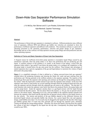
  • 14. 14 Figure 6 – Simulator Input Screen for Definition of Gas Separator Dimensions and Pumping System and Fluid Properties.
  • 15. 15 Figure 7 – Separator operation simulation and visualization screen. Pump Displacement = 100 Bbl/day SPM = 6.95 Gas/Liquid Interface 5.5 17 #/ft 3.00 2.75 1.35 2-3/8 Collar Size Separator 42 1.084