1. Chapter 18
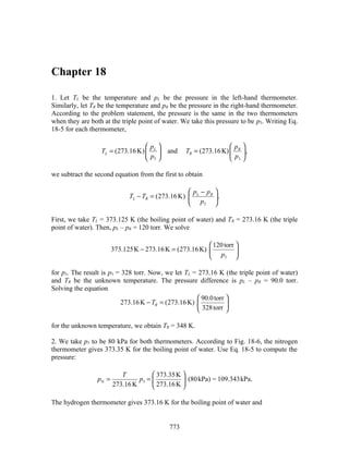
1. Let TL be the temperature and pL be the pressure in the left-hand thermometer.
Similarly, let TR be the temperature and pR be the pressure in the right-hand thermometer.
According to the problem statement, the pressure is the same in the two thermometers
when they are both at the triple point of water. We take this pressure to be p3. Writing Eq.
18-5 for each thermometer,
p p
TL = (273.16 K) L and TR = (273.16 K) R ,
p3 p3
we subtract the second equation from the first to obtain
p − pR
TL − TR = (273.16 K) L .
p3
First, we take TL = 373.125 K (the boiling point of water) and TR = 273.16 K (the triple
point of water). Then, pL – pR = 120 torr. We solve
120 torr
373.125K − 273.16 K = (273.16 K)
p3
for p3. The result is p3 = 328 torr. Now, we let TL = 273.16 K (the triple point of water)
and TR be the unknown temperature. The pressure difference is pL – pR = 90.0 torr.
Solving the equation
90.0 torr
273.16 K − TR = (273.16 K)
328 torr
for the unknown temperature, we obtain TR = 348 K.
2. We take p3 to be 80 kPa for both thermometers. According to Fig. 18-6, the nitrogen
thermometer gives 373.35 K for the boiling point of water. Use Eq. 18-5 to compute the
pressure:
T 373.35 K
pN = p3 = (80 kPa) = 109.343kPa.
273.16 K 273.16 K
The hydrogen thermometer gives 373.16 K for the boiling point of water and
773
2. 6 CHAPTER 18
373.16 K
pH = (80 kPa) = 109.287 kPa.
273.16 K
(a) The difference is pN − pH = 0.056 kPa ≈ 0.06 kPa .
(b) The pressure in the nitrogen thermometer is higher than the pressure in the hydrogen
thermometer.
3. From Eq. 18-6, we see that the limiting value of the pressure ratio is the same as the
absolute temperature ratio: (373.15 K)/(273.16 K) = 1.366.
4. (a) Let the reading on the Celsius scale be x and the reading on the Fahrenheit scale be
y. Then y = 9 x + 32 . For x = –71°C, this gives y = –96°F.
5
(b) The relationship between y and x may be inverted to yield x = 5 ( y − 32) . Thus, for y
9
= 134 we find x ≈ 56.7 on the Celsius scale.
5. (a) Let the reading on the Celsius scale be x and the reading on the Fahrenheit scale be
y. Then y = 9 x + 32 . If we require y = 2x, then we have
5
9
2x = x + 32 ⇒ x = (5) (32) =160°C
5
which yields y = 2x = 320°F.
(b) In this case, we require y = 1 x and find
2
1 9 (10)(32)
x = x + 32 ⇒ x=− ≈ −24.6°C
2 5 13
which yields y = x/2 = –12.3°F.
6. We assume scales X and Y are linearly related in the sense that reading x is related to
reading y by a linear relationship y = mx + b. We determine the constants m and b by
solving the simultaneous equations:
−70.00 = m ( −125.0 ) + b
−30.00 = m ( 375.0 ) + b
which yield the solutions m = 40.00/500.0 = 8.000 × 10⁻² and b = –60.00. With these
values, we find x for y = 50.00:
3. 7
y − b 50.00 + 60.00
x= = = 1375° X .
m 0.08000
7. We assume scale X is a linear scale in the sense that if its reading is x then it is related
to a reading y on the Kelvin scale by a linear relationship y = mx + b. We determine the
constants m and b by solving the simultaneous equations:
373.15 = m(−53.5) + b
273.15 = m(−170) + b
which yield the solutions m = 100/(170 – 53.5) = 0.858 and b = 419. With these values,
we find x for y = 340:
y − b 340 − 419
x= = = − 92.1° X .
m 0.858
8. The change in length for the aluminum pole is
∆l = l 0α A1∆T = (33m)(23 ×10−6 / C°)(15 °C) = 0.011m.
9. Since a volume is the product of three lengths, the change in volume due to a
temperature change ∆T is given by ∆V = 3αV ∆T, where V is the original volume and α is
the coefficient of linear expansion. See Eq. 18-11. Since V = (4π/3)R3, where R is the
original radius of the sphere, then
4π
∆V = 3α R 3 ÷ ∆T = ( 23 ×10−6 / C° ) ( 4π ) ( 10 cm ) ( 100 °C ) = 29 cm 3 .
3
3
The value for the coefficient of linear expansion is found in Table 18-2.
10. (a) The coefficient of linear expansion α for the alloy is
∆L 10.015cm − 10.000 cm
α= = = 1.88 ×10⁻⁵ / C°.
L∆T (10.01cm)(100°C − 20.000°C)
Thus, from 100°C to 0°C we have
∆L = Lα∆T = (10.015cm)(1.88 × 10⁻⁵ / C°)(0°C − 100°C) = − 1.88 × 10 −2 cm.
The length at 0°C is therefore L′ = L + ∆L = (10.015 cm – 0.0188 cm) = 9.996 cm.
(b) Let the temperature be Tx. Then from 20°C to Tx we have
4. 8 CHAPTER 18
∆L = 10.009 cm − 10.000cm = α L∆T = (1.88 × 10 −5 / C°)(10.000cm) ∆T ,
giving ∆T = 48 °C. Thus, Tx = (20°C + 48 °C )= 68°C.
11. The new diameter is
D = D0 (1 + α A1∆T ) = (2.725cm)[1+ (23 ×10 −6 / C°)(100.0°C − 0.000°C)] = 2.731cm.
12. The increase in the surface area of the brass cube (which has six faces), which had
side length is L at 20°, is
∆A = 6( L + ∆L) 2 − 6 L2 ≈ 12 L∆L = 12α b L2 ∆T = 12 (19 × 10 −6 / C°) (30 cm) 2 (75°C − 20°C)
= 11cm 2 .
13. The volume at 30°C is given by
V ' = V (1 + β∆T ) = V (1 + 3α∆T ) = (50.00 cm 3 )[1 + 3(29.00 ×10 −6 / C°) (30.00°C − 60.00°C)]
= 49.87 cm3
where we have used β = 3α.
14. (a) We use ρ = m/V and
∆ρ = ∆ (m/V ) = m∆ (1/V ) ; − m∆V/V 2 = − ρ (∆V/V ) = −3 ρ (∆L/L).
The percent change in density is
∆ρ ∆L
= −3 = −3(0.23%) = −0.69%.
ρ L
(b) Since α = ∆L/(L∆T ) = (0.23 × 10⁻²) / (100°C – 0.0°C) = 23 × 10–6 /C°, the metal is
aluminum (using Table 18-2).
15. If Vc is the original volume of the cup, αa is the coefficient of linear expansion of
aluminum, and ∆T is the temperature increase, then the change in the volume of the cup
is ∆Vc = 3αa Vc ∆T. See Eq. 18-11. If β is the coefficient of volume expansion for
glycerin then the change in the volume of glycerin is ∆Vg = βVc ∆T. Note that the original
volume of glycerin is the same as the original volume of the cup. The volume of glycerin
that spills is
5. 9
∆Vg − ∆Vc = ( β − 3α a ) Vc ∆T = ( 5.1× 10⁻⁴ / C° ) − 3 ( 23 ×10 −6 / C° ) ( 100 cm 3 ) ( 6.0 °C )
= 0.26 cm .3
16. The change in length for the section of the steel ruler between its 20.05 cm mark and
20.11 cm mark is
∆Ls = Lsα s ∆T = (20.11cm)(11 × 10 −6 / C°)(270°C − 20°C) = 0.055cm.
Thus, the actual change in length for the rod is
∆L = (20.11 cm – 20.05 cm) + 0.055 cm = 0.115 cm.
The coefficient of thermal expansion for the material of which the rod is made is then
∆L 0.115 cm
α= = = 23 × 10−6 / C°.
∆T 270°C − 20°C
17. After the change in temperature the diameter of the steel rod is Ds = Ds0 + αsDs0 ∆T
and the diameter of the brass ring is Db = Db0 + αbDb0 ∆T, where Ds0 and Db0 are the
original diameters, αs and αb are the coefficients of linear expansion, and ∆T is the
change in temperature. The rod just fits through the ring if Ds = Db. This means
Ds0 + αsDs0 ∆T = Db0 + αbDb0 ∆T.
Therefore,
Ds 0 − Db 0 3.000 cm − 2.992 cm
∆T = =
α b Db 0 − α s Ds 0 ( 19.00 × 10 / C° ) ( 2.992 cm ) − ( 11.00 × 10⁻⁶ / C° ) ( 3.000 cm )
−6
= 335.0 °C.
The temperature is T = (25.00°C + 335.0 °C) = 360.0°C.
18. (a) Since A = πD2/4, we have the differential dA = 2(πD/4)dD. Dividing the latter
relation by the former, we obtain dA/A = 2 dD/D. In terms of ∆'s, this reads
∆A ∆D ∆D
=2 for = 1.
A D D
We can think of the factor of 2 as being due to the fact that area is a two-dimensional
quantity. Therefore, the area increases by 2(0.18%) = 0.36%.
(b) Assuming that all dimensions are allowed to freely expand, then the thickness
increases by 0.18%.
(c) The volume (a three-dimensional quantity) increases by 3(0.18%) = 0.54%.
6. 10 CHAPTER 18
(d) The mass does not change.
(e) The coefficient of linear expansion is
∆D 0.18 ×10⁻²
α= = = 1.8 ×10⁻⁵ /C°.
D∆T 100°C
19. The initial volume V0 of the liquid is h0A0 where A0 is the initial cross-section area and
h0 = 0.64 m. Its final volume is V = hA where h – h0 is what we wish to compute. Now,
the area expands according to how the glass expands, which we analyze as follows:
Using A = π r 2 , we obtain
dA = 2π r dr = 2π r ( rα dT ) = 2α (π r 2 )dT = 2α A dT .
Therefore, the height is
V V0 ( 1 + β liquid ∆T )
h= = .
A A0 ( 1 + 2α glass ∆T )
Thus, with V0/A0 = h0 we obtain
1 + β liquid ∆T 1 + ( 4 ×10⁻⁵ ) ( 10° )
h − h0 = h0 − 1÷ = ( 0.64 ) ÷ = 1.3 ×10⁻⁴ m.
1 + 2α glass ∆T ÷
1 + 2 ( 1× 10⁻⁵ ) ( 10° ) ÷
20. We divide Eq. 18-9 by the time increment ∆t and equate it to the (constant) speed v =
100 × 10–9 m/s.
∆T
v = α L0
∆t
where L0 = 0.0200 m and α = 23 × 10–6/C°. Thus, we obtain
∆T C° K
= 0.217 = 0.217 .
∆t s s
21. Consider half the bar. Its original length is l 0 = L0 / 2 and its length after the
temperature increase is l = l 0 + α l 0 ∆T . The old position of the half-bar, its new position,
and the distance x that one end is displaced form a right triangle, with a hypotenuse of
length l , one side of length l 0 , and the other side of length x. The Pythagorean theorem
yields
x 2 = l 2 − l 2 = l 2 (1 + α∆T ) 2 − l 2 .
0 0 0
7. 11
Since the change in length is small we may approximate (1 + α ∆T )2 by 1 + 2α ∆T,
where the small term (α ∆T )2 was neglected. Then,
x 2 = l 2 + 2l 2α ∆T − l 2 = 2l 2α ∆T
0 0 0 0
and
3.77 m (
x = l 0 2α ∆T = 2 25 × 10−6 /C° ) ( 32° C ) = 7.5 ×10 −2 m.
2
22. (a) The specific heat is given by c = Q/m(Tf – Ti), where Q is the heat added, m is the
mass of the sample, Ti is the initial temperature, and Tf is the final temperature. Thus,
recalling that a change in Celsius degrees is equal to the corresponding change on the
Kelvin scale,
314 J
c= = 523J/kg ⋅ K.
( 30.0 × 10 kg ) ( 45.0°C − 25.0°C )
−3
(b) The molar specific heat is given by
Q 314 J
cm = = = 26.2 J/mol ⋅ K.
N ( T f − Ti ) ( 0.600 mol ) ( 45.0°C − 25.0°C )
(c) If N is the number of moles of the substance and M is the mass per mole, then m =
NM, so
m 30.0 × 10⁻³ kg
N= = = 0.600 mol.
M 50 × 10−3 kg/mol
23. We use Q = cm∆T. The textbook notes that a nutritionist's “Calorie” is equivalent to
1000 cal. The mass m of the water that must be consumed is
Q 3500 × 103 cal
m= = = 94.6 × 10⁴ g,
c∆T ( 1g/cal ⋅ C° ) ( 37.0°C − 0.0°C )
which is equivalent to 9.46 × 10⁴ g/(1000 g/liter) = 94.6 liters of water. This is certainly
too much to drink in a single day!
24. The amount of water m that is frozen is
Q 50.2 kJ
m= = = 0.151kg = 151g.
LF 333kJ/kg
Therefore the amount of water which remains unfrozen is 260 g – 151 g = 109 g.
8. 12 CHAPTER 18
25. The melting point of silver is 1235 K, so the temperature of the silver must first be
raised from 15.0° C (= 288 K) to 1235 K. This requires heat
Q = cm(T f − Ti ) = (236 J/kg ⋅ K)(0.130 kg)(1235°C − 288°C) = 2.91 × 10 4 J.
Now the silver at its melting point must be melted. If LF is the heat of fusion for silver
this requires
Q = mLF = ( 0.130 kg ) ( 105 × 103 J/kg ) = 1.36 × 10⁴ J.
The total heat required is ( 2.91 × 10⁴ J + 1.36 × 10⁴ J ) = 4.27 × 10⁴ J.
26. (a) The water (of mass m) releases energy in two steps, first by lowering its
temperature from 20°C to 0°C, and then by freezing into ice. Thus the total energy
transferred from the water to the surroundings is
Q = cwm∆T + LF m = ( 4190 J/kg ⋅ K ) ( 125kg ) ( 20°C ) + ( 333kJ/kg ) ( 125kg ) = 5.2 × 10⁷ J.
(b) Before all the water freezes, the lowest temperature possible is 0°C, below which the
water must have already turned into ice.
27. The mass m = 0.100 kg of water, with specific heat c = 4190 J/kg·K, is raised from an
initial temperature Ti = 23°C to its boiling point Tf = 100°C. The heat input is given by Q
= cm(Tf – Ti). This must be the power output of the heater P multiplied by the time t; Q =
Pt. Thus,
Q cm (T f − Ti ) ( 4190 J/kg ⋅ K ) ( 0.100 kg ) ( 100° C − 23°C )
t= = = = 160s.
P P 200 J/s
28. The work the man has to do to climb to the top of Mt. Everest is given by
W = mgy = (73.0 kg)(9.80 m/s2)(8840 m) = 6.32 × 10⁶ J.
Thus, the amount of butter needed is
m=
(6.32 × 10⁶ J) ( 1.00cal
4.186J ) ≈ 250 g.
6000 cal/g
29. Let the mass of the steam be ms and that of the ice be mi. Then
LF mc + cw mc (T f − 0.0°C) = ms Ls + ms cw (100°C − T f ) ,
where Tf = 50°C is the final temperature. We solve for ms:
9. 13
LF mc + cw mc (T f − 0.0°C) (79.7 cal / g)(150 g) + (1cal / g·°C)(150g)(50°C − 0.0°C)
ms = =
Ls + cw (100°C − T f ) 539 cal / g + (1cal / g ×C°)(100°C − 50°C)
= 33g.
30. (a) Using Eq. 18-17, the heat transferred to the water is
Qw = cw mw ∆T + LV ms = ( 1cal/g ×C° ) ( 220 g ) ( 100°C − 20.0°C ) + ( 539 cal/g ) ( 5.00 g )
= 20.3kcal.
(b) The heat transferred to the bowl is
Qb = cbmb ∆T = ( 0.0923cal/g ⋅ C° ) ( 150 g ) ( 100° C − 20.0° C ) = 1.11kcal.
(c) If the original temperature of the cylinder be Ti, then Qw + Qb = ccmc(Ti – Tf), which
leads to
Q + Qb 20.3kcal + 1.11kcal
Ti = w + Tf = + 100°C = 873°C.
cc mc ( 0.0923cal/g ⋅ C° ) ( 300 g )
31. We note from Eq. 18-12 that 1 Btu = 252 cal. The heat relates to the power, and to the
temperature change, through Q = Pt = cm∆T. Therefore, the time t required is
cm∆T (1000 cal / kg × °)(40 gal)(1000 kg / 264 gal)(100°F − 70°F)(5°C / 9°F)
C
t= =
P (2.0 × 10⁵ Btu / h)(252.0 cal / Btu)(1 h / 60 min)
= 3.0 min .
The metric version proceeds similarly:
c ρV ∆T (4190 J/kg·C°)(1000 kg/m 3 )(150 L)(1 m 3 /1000 L)(38°C − 21°C)
t= =
P (59000 J/s)(60 s /1min)
= 3.0 min.
32. We note that the heat capacity of sample B is given by the reciprocal of the slope of
the line in Figure 18-32(b) (compare with Eq. 18-14). Since the reciprocal of that slope is
16/4 = 4 kJ/kg·C°, then cB = 4000 J/kg·C° = 4000 J/kg·K (since a change in Celsius is
equivalent to a change in Kelvins). Now, following the same procedure as shown in
Sample Problem 18-4, we find
cA mA (Tf − TA) + cB mB (Tf − TB) = 0
cA (5.0 kg)(40°C – 100°C) + (4000 J/kg·C°)(1.5 kg)(40°C – 20°C) = 0
which leads to cA = 4.0×10² J/kg·K.
10. 14 CHAPTER 18
33. The power consumed by the system is
1 cm∆T 1 (4.18 J / g × C)(200 ×10 cm )(1g / cm )(40°C − 20°C)
° 3 3 3
P= ÷ = ÷
20% t 20% (1.0 h)(3600s / h)
= 2.3 ×10⁴ W.
2.3 × 10⁴ W
The area needed is then A = 2
= 33m 2 .
700 W / m
34. While the sample is in its liquid phase, its temperature change (in absolute values) is
| ∆T | = 30 °C. Thus, with m = 0.40 kg, the absolute value of Eq. 18-14 leads to
|Q| = c m |∆T | = ( 3000 J/ kg × C )(0.40 kg)(30 °C ) = 36000 J .
°
The rate (which is constant) is
P = |Q| / t = (36000 J)/(40 min) = 900 J/min,
which is equivalent to 15 Watts.
(a) During the next 30 minutes, a phase change occurs which is described by Eq. 18-16:
|Q| = P t = (900 J/min)(30 min) = 27000 J = L m .
Thus, with m = 0.40 kg, we find L = 67500 J/kg ≈ 68 kJ/kg.
(b) During the final 20 minutes, the sample is solid and undergoes a temperature change
(in absolute values) of | ∆T | = 20 C°. Now, the absolute value of Eq. 18-14 leads to
c = = = = 2250 ≈ 2.3 .
35. We denote the ice with subscript I and the coffee with c, respectively. Let the final
temperature be Tf. The heat absorbed by the ice is
QI = λFmI + mIcw (Tf – 0°C),
and the heat given away by the coffee is |Qc| = mwcw (TI – Tf). Setting QI = |Qc|, we solve
for Tf :
mwcwTI − λ F mI (130 g) (4190 J/kg ×C°) (80.0°C) − (333 × 103 J/g) (12.0 g)
Tf = =
(mI + mc )cw (12.0 g +130 g ) (4190 J/kg ×C°)
= 66.5°C.
11. 15
Note that we work in Celsius temperature, which poses no difficulty for the J/kg·K values
of specific heat capacity (see Table 18-3) since a change of Kelvin temperature is
numerically equal to the corresponding change on the Celsius scale. Therefore, the
temperature of the coffee will cool by |∆T | = 80.0°C – 66.5°C = 13.5C°.
36. (a) Eq. 18-14 (in absolute value) gives
|Q| = (4190 J/ kg × C )(0.530 kg)(40 °C) = 88828 J.
°
Since is assumed constant (we will call it P) then we have
P = = = 37 W .
(b) During that same time (used in part (a)) the ice warms by 20 C°. Using Table 18-3
and Eq. 18-14 again we have
mice = = = 2.0 kg .
(c) To find the ice produced (by freezing the water that has already reached 0°C – so we
concerned with the 40 min < t < 60 min time span), we use Table 18-4 and Eq. 18-16:
mwater becoming ice = = = 0.13 kg.
37. To accomplish the phase change at 78°C,
Q = LVm = (879 kJ/kg) (0.510 kg) = 448.29 kJ
must be removed. To cool the liquid to –114°C,
Q = cm|∆T| = (2.43 kJ/ kg ×K ) (0.510 kg) (192 K) = 237.95 kJ,
must be removed. Finally, to accomplish the phase change at –114°C,
Q = LFm = (109 kJ/kg) (0.510 kg) = 55.59 kJ
must be removed. The grand total of heat removed is therefore (448.29 + 237.95 + 55.59)
kJ = 742 kJ.
38. The heat needed is found by integrating the heat capacity:
Tf Tf 15.0° C
Q = ∫ cm dT = m ∫ cdT = (2.09) ∫ (0.20 + 0.14T + 0.023T 2 ) dT
Ti Ti 5.0° C
15.0
= (2.0) (0.20T + 0.070T 2 + 0.00767T 3 ) (cal)
5.0
= 82 cal.
12. 16 CHAPTER 18
39. We compute with Celsius temperature, which poses no difficulty for the J/kg·K
values of specific heat capacity (see Table 18-3) since a change of Kelvin temperature is
numerically equal to the corresponding change on the Celsius scale. If the equilibrium
temperature is Tf then the energy absorbed as heat by the ice is
QI = LFmI + cwmI(Tf – 0°C),
while the energy transferred as heat from the water is Qw = cwmw(Tf – Ti). The system is
insulated, so Qw + QI = 0, and we solve for Tf :
cwmwTi − LF mI
Tf = .
( mI + mC )cw
(a) Now Ti = 90°C so
(4190J / kg ⋅ C°)(0.500 kg)(90°C) − (333 × 103 J / kg)(0.500 kg)
Tf = = 5.3°C.
(0.500 kg + 0.500 kg)(4190 J / kg ⋅ C°)
(b) Since no ice has remained at T f = 5.3°C , we have m f = 0 .
(c) If we were to use the formula above with Ti = 70°C, we would get Tf < 0, which is
impossible. In fact, not all the ice has melted in this case and the equilibrium temperature
is Tf = 0°C.
(d) The amount of ice that melts is given by
cwmw (Ti − 0°C) (4190 J / kg ⋅ C°)(0.500 kg)(70C°)
m′ =
I = = 0.440 kg.
LF 333 × 103 J / kg
Therefore, the amount of (solid) ice remaining is mf = mI – m'I = 500 g – 440 g = 60.0 g,
and (as mentioned) we have Tf = 0°C (because the system is an ice-water mixture in
thermal equilibrium).
40. (a) Using Eq. 18-32, we find the rate of energy conducted upward to be
Q T −T 5.0 °C
Pcond = = kA H C = (0.400 W/m × C) A
° = (16.7 A) W.
t L 0.12 m
Recall that a change in Celsius temperature is numerically equivalent to a change on the
Kelvin scale.
(b) The heat of fusion in this process is Q = LF m, where LF = 3.33 ×10 J/kg .
5
Differentiating the expression with respect to t and equating the result with Pcond , we have
13. 17
dQ dm
Pcond = = LF .
dt dt
Thus, the rate of mass converted from liquid to ice is
dm Pcond 16.7 A W
= = = (5.02 × 10⁻⁵ A) kg/s .
dt LF 3.33 ×10 J/kg
5
(c) Since m = ρV = ρ Ah , differentiating both sides of the expression gives
dm d dh
= ( ρ Ah ) = ρ A .
dt dt dt
Thus, the rate of change of the icicle length is
dh 1 dm 5.02 ×10⁻⁵ kg/m 2 ×s
= = = 5.02 ×10⁻⁸ m/s
dt ρ A dt 1000 kg/m 3
41. (a) We work in Celsius temperature, which poses no difficulty for the J/kg·K values
of specific heat capacity (see Table 18-3) since a change of Kelvin temperature is
numerically equal to the corresponding change on the Celsius scale. There are three
possibilities:
• None of the ice melts and the water-ice system reaches thermal equilibrium at a
temperature that is at or below the melting point of ice.
• The system reaches thermal equilibrium at the melting point of ice, with some of the ice
melted.
• All of the ice melts and the system reaches thermal equilibrium at a temperature at or
above the melting point of ice.
First, suppose that no ice melts. The temperature of the water decreases from TWi = 25°C
to some final temperature Tf and the temperature of the ice increases from TIi = –15°C to
Tf. If mW is the mass of the water and cW is its specific heat then the water rejects heat
| Q | = cW mW (TWi − T f ).
If mI is the mass of the ice and cI is its specific heat then the ice absorbs heat
Q = cI mI (T f − TIi ).
Since no energy is lost to the environment, these two heats (in absolute value) must be
the same. Consequently,
14. 18 CHAPTER 18
cW mW (TWi − T f ) = cI mI (T f − TIi ).
The solution for the equilibrium temperature is
cW mW TWi + cI mI TIi
Tf =
cW mW + cI mI
(4190 J / kg ⋅ K)(0.200 kg)(25°C) + (2220 J/kg ⋅ K)(0.100 kg)( −15°C)
=
(4190 J/kg ⋅ K)(0.200 kg) + (2220 J/kg ⋅ K)(0.100 kg)
= 16.6°C.
This is above the melting point of ice, which invalidates our assumption that no ice has
melted. That is, the calculation just completed does not take into account the melting of
the ice and is in error. Consequently, we start with a new assumption: that the water and
ice reach thermal equilibrium at Tf = 0°C, with mass m (< mI) of the ice melted. The
magnitude of the heat rejected by the water is
| Q | = cW mW TWi ,
and the heat absorbed by the ice is
Q = cI mI (0 − TIi ) + mLF ,
where LF is the heat of fusion for water. The first term is the energy required to warm all
the ice from its initial temperature to 0°C and the second term is the energy required to
melt mass m of the ice. The two heats are equal, so
cW mW TWi = −cI mI TIi + mLF .
This equation can be solved for the mass m of ice melted:
cW mW TWi + cI mI TIi
m=
LF
(4190 J / kg ⋅ K)(0.200 kg)(25°C) + (2220J / kg ⋅ K)(0.100 kg)( −15°C )
=
333 × 103 J / kg
= 5.3 × 10⁻² kg = 53g.
Since the total mass of ice present initially was 100 g, there is enough ice to bring the
water temperature down to 0°C. This is then the solution: the ice and water reach thermal
equilibrium at a temperature of 0°C with 53 g of ice melted.
(b) Now there is less than 53 g of ice present initially. All the ice melts and the final
temperature is above the melting point of ice. The heat rejected by the water is
15. 19
Q = cW mW (TW i − T f )
and the heat absorbed by the ice and the water it becomes when it melts is
Q = cI mI (0 − TIi ) + cW mI (T f − 0) + mI LF .
The first term is the energy required to raise the temperature of the ice to 0°C, the second
term is the energy required to raise the temperature of the melted ice from 0°C to Tf, and
the third term is the energy required to melt all the ice. Since the two heats are equal,
cW mW (TW i − T f ) = cI mI (−TI i ) + cW mI T f + mI LF .
The solution for Tf is
cW mW TW i + cI mI TIi − mI LF
Tf = .
cW (mW + mI )
Inserting the given values, we obtain Tf = 2.5°C.
42. If the ring diameter at 0.000°C is Dr0 then its diameter when the ring and sphere are in
thermal equilibrium is
Dr = Dr 0 (1 + α cT f ),
where Tf is the final temperature and αc is the coefficient of linear expansion for copper.
Similarly, if the sphere diameter at Ti (= 100.0°C) is Ds0 then its diameter at the final
temperature is
Ds = Ds 0 [1 + α a (T f − Ti )],
where αa is the coefficient of linear expansion for aluminum. At equilibrium the two
diameters are equal, so
Dr 0 (1 + α cT f ) = Ds 0 [1 + α a (T f − Ti )].
The solution for the final temperature is
Dr 0 − Ds 0 + Ds 0α aTi
Tf =
Ds 0α a − Dr 0α c
2.54000 cm − 2.54508cm + (2.54508cm)(23 ×10 −6 /C°)(100.0°C)
=
(2.54508cm)(23 ×10 −6 / C°) − (2.54000 cm) (17 × 10 −6 /C°)
= 50.38°C.
16. 20 CHAPTER 18
The expansion coefficients are from Table 18-2 of the text. Since the initial temperature
of the ring is 0°C, the heat it absorbs is Q = cc mrT f , where cc is the specific heat of
copper and mr is the mass of the ring. The heat rejected up by the sphere is
Q = ca ms (Ti − T f )
where ca is the specific heat of aluminum and ms is the mass of the sphere. Since these
two heats are equal,
cc mrT f = ca ms (Ti − T f ),
we use specific heat capacities from the textbook to obtain
cc mrT f (386 J/kg ⋅ K)(0.0200 kg)(50.38°C)
ms = = = 8.71 × 10⁻³ kg.
ca (Ti − T f ) (900 J/kg ⋅ K)(100°C − 50.38°C)
43. Over a cycle, the internal energy is the same at the beginning and end, so the heat Q
absorbed equals the work done: Q = W. Over the portion of the cycle from A to B the
pressure p is a linear function of the volume V and we may write
10 20
p= Pa + Pa/m 3 V ,
3 3
where the coefficients were chosen so that p = 10 Pa when V = 1.0 m3 and p = 30 Pa
when V = 4.0 m3. The work done by the gas during this portion of the cycle is
4
4 4 10 20 10 10 2
WAB = ∫1
pdV = ∫1 + V ÷dV = V + V ÷
3 3 3 3 1
40 160 10 10
= + − − ÷J = 60 J.
3 3 3 3
The BC portion of the cycle is at constant pressure and the work done by the gas is
WBC = p∆V = (30 Pa)(1.0 m3 – 4.0 m3) = –90 J.
The CA portion of the cycle is at constant volume, so no work is done. The total work
done by the gas is
W = WAB + WBC + WCA = 60 J – 90 J + 0 = –30 J
and the total heat absorbed is Q = W = –30 J. This means the gas loses 30 J of energy in
the form of heat.
44. (a) Since work is done on the system (perhaps to compress it) we write W = –200 J.
17. 21
(b) Since heat leaves the system, we have Q = –70.0 cal = –293 J.
(c) The change in internal energy is ∆Eint = Q – W = –293 J – (–200 J) = –93 J.
45. (a) One part of path A represents a constant pressure process. The volume changes
from 1.0 m3 to 4.0 m3 while the pressure remains at 40 Pa. The work done is
WA = p∆V = (40 Pa)(4.0 m 3 − 1.0 m 3 ) = 1.2 ×10² J.
(b) The other part of the path represents a constant volume process. No work is done
during this process. The total work done over the entire path is 120 J. To find the work
done over path B we need to know the pressure as a function of volume. Then, we can
evaluate the integral W = ∫ p dV. According to the graph, the pressure is a linear function
of the volume, so we may write p = a + bV, where a and b are constants. In order for the
pressure to be 40 Pa when the volume is 1.0 m3 and 10 Pa when the volume is 4.00 m3 the
values of the constants must be a = 50 Pa and b = –10 Pa/m3. Thus,
p = 50 Pa – (10 Pa/m3)V
and
WB = ∫ p dV = ∫ ( 50 − 10V ) dV = ( 50V − 5V 2 )
4 4
4
1 = 200 J − 50 J − 80 J + 5.0 J = 75 J.
1 1
(c) One part of path C represents a constant pressure process in which the volume
changes from 1.0 m3 to 4.0 m3 while p remains at 10 Pa. The work done is
WC = p∆V = (10 Pa)(4.0 m 3 − 1.0 m 3 ) = 30 J.
The other part of the process is at constant volume and no work is done. The total work is
30 J. We note that the work is different for different paths.
46. During process A → B, the system is expanding, doing work on its environment, so
W > 0, and since ∆Eint > 0 is given then Q = W + ∆Eint must also be positive.
(a) Q > 0.
(b) W > 0.
During process B → C, the system is neither expanding nor contracting. Thus,
(c) W = 0.
(d) The sign of ∆Eint must be the same (by the first law of thermodynamics) as that of Q
which is given as positive. Thus, ∆Eint > 0.
18. 22 CHAPTER 18
During process C → A, the system is contracting. The environment is doing work on the
system, which implies W < 0. Also, ∆Eint < 0 because ∑ ∆Eint = 0 (for the whole cycle)
and the other values of ∆Eint (for the other processes) were positive. Therefore, Q = W +
∆Eint must also be negative.
(e) Q < 0.
(f) W < 0.
(g) ∆Eint < 0.
(h) The area of a triangle is 1 (base)(height). Applying this to the figure, we find
2
| Wnet | = 2 (2.0 m )(20 Pa) = 20 J . Since process C → A involves larger negative work (it
1 3
occurs at higher average pressure) than the positive work done during process A → B,
then the net work done during the cycle must be negative. The answer is therefore Wnet =
–20 J.
47. We note that there is no work done in the process going from d to a, so Qda = ∆Eint da
= 80 J. Also, since the total change in internal energy around the cycle is zero, then
∆Eint ac + ∆Eint cd + ∆Eint da = 0
−200 J + ∆Eint cd + 80 J =0
which yields ∆Eint cd = 120 J. Thus, applying the first law of thermodynamics to the c to
d process gives the work done as
Wcd = Qcd − ∆Eint cd = 180 J – 120 J = 60 J.
48. (a) We note that process a to b is an expansion, so W > 0 for it. Thus, Wab = +5.0 J.
We are told that the change in internal energy during that process is +3.0 J, so application
of the first law of thermodynamics for that process immediately yields Qab = +8.0 J.
(b) The net work (+1.2 J) is the same as the net heat (Qab + Qbc + Qca), and we are told
that Qca = +2.5 J. Thus we readily find Qbc = (1.2 – 8.0 – 2.5) J = −9.3 J.
49. (a) The change in internal energy ∆Eint is the same for path iaf and path ibf. According
to the first law of thermodynamics, ∆Eint = Q – W, where Q is the heat absorbed and W is
the work done by the system. Along iaf
∆Eint = Q – W = 50 cal – 20 cal = 30 cal.
Along ibf ,
W = Q – ∆Eint = 36 cal – 30 cal = 6.0 cal.
19. 23
(b) Since the curved path is traversed from f to i the change in internal energy is –30 cal
and Q = ∆Eint + W = –30 cal – 13 cal = – 43 cal.
(c) Let ∆Eint = Eint, f – Eint, i. Then, Eint, f = ∆Eint + Eint, i = 30 cal + 10 cal = 40 cal.
(d) The work Wbf for the path bf is zero, so Qbf = Eint, f – Eint, b = 40 cal – 22 cal = 18 cal.
(e) For the path ibf, Q = 36 cal so Qib = Q – Qbf = 36 cal – 18 cal = 18 cal.
50. Since the process is a complete cycle (beginning and ending in the same
thermodynamic state) the change in the internal energy is zero and the heat absorbed by
the gas is equal to the work done by the gas: Q = W. In terms of the contributions of the
individual parts of the cycle QAB + QBC + QCA = W and
QCA = W – QAB – QBC = +15.0 J – 20.0 J – 0 = –5.0 J.
This means 5.0 J of energy leaves the gas in the form of heat.
51. The rate of heat flow is given by
TH − TC
Pcond = kA ,
L
where k is the thermal conductivity of copper (401 W/m·K), A is the cross-sectional area
(in a plane perpendicular to the flow), L is the distance along the direction of flow
between the points where the temperature is TH and TC. Thus,
( 401W/m ⋅ K ) ( 90.0 × 10⁻⁴ m 2 ) ( 125°C − 10.0°C )
Pcond = = 1.66 × 10³ J/s.
0.250 m
The thermal conductivity is found in Table 18-6 of the text. Recall that a change in
Kelvin temperature is numerically equivalent to a change on the Celsius scale.
52. (a) We estimate the surface area of the average human body to be about 2 m 2 and the
skin temperature to be about 300 K (somewhat less than the internal temperature of
310 K). Then from Eq. 18-37
Pr = σε AT 4 ≈ ( 5.67 × 10⁻⁸ W/m 2 ⋅ K 4 ) ( 0.9 ) ( 2.0 m 2 ) ( 300 K ) = 8 × 10² W.
4
(b) The energy lost is given by
∆E = Pr ∆t = ( 8 × 10² W ) ( 30s ) = 2 × 10⁴ J.
20. 24 CHAPTER 18
53. (a) Recalling that a change in Kelvin temperature is numerically equivalent to a
change on the Celsius scale, we find that the rate of heat conduction is
kA ( TH − TC ) ( 401W/m ×K ) ( 4.8 × 10⁻⁴ m 2 ) ( 100 °C )
Pcond = = = 16 J/s.
L 1.2 m
(b) Using Table 18-4, the rate at which ice melts is
dm Pcond 16 J/s
= = = 0.048g/s.
dt LF 333J/g
54. We refer to the polyurethane foam with subscript p and silver with subscript s. We
use Eq. 18–32 to find L = kR.
(a) From Table 18-6 we find kp = 0.024 W/m·K so
Lp = k p R p
= ( 0.024 W/m ×K ) ( 30 ft 2 ×F°×h/Btu ) ( 1m/3.281ft ) ( 5C° / 9F° ) ( 3600 s/h ) ( 1Btu/1055 J )
2
= 0.13m.
(b) For silver ks = 428 W/m·K, so
kR 428 ( 30 )
Ls = k s Rs = s s Lp = ( 0.13m ) = 2.3 × 10 m.
3
k p Rp 0.024 ( 30 )
55. We use Eqs. 18-38 through 18-40. Note that the surface area of the sphere is given by
A = 4πr2, where r = 0.500 m is the radius.
(a) The temperature of the sphere is T = (273.15 + 27.00) K = 300.15 K. Thus
Pr = σε AT 4 = ( 5.67 × 10⁻⁸ W m 2 ×K 4 ) ( 0.850 ) ( 4π ) ( 0.500 m ) ( 300.15 K )
2 4
= 1.23 ×10³ W.
(b) Now, Tenv = 273.15 + 77.00 = 350.15 K so
Pa = σε ATenv = (5.67 × 10⁻⁸ W m 2 ×K 4 )(0.850)(4π ) ( 0.500 m ) ( 350.15 K )
2 4
4
= 2.28 ×10³ W.
(c) From Eq. 18-40, we have
Pn = Pa − Pr = 2.28 × 10³ W − 1.23 × 10³ W = 1.05 × 10³ W.
21. 25
56. (a) The surface area of the cylinder is given by
A = 2π r 1 + 2π rh1 = 2π (2.5 ×10⁻² m)2 + 2π (2.5 ×10⁻² m)(5.0 ×10⁻² m) = 1.18 ×10⁻² m2 ,
1
2
1
its temperature is T1 = 273 + 30 = 303 K, and the temperature of the environment is Tenv =
273 + 50 = 323 K. From Eq. 18-39 we have
P = σε A1 ( Tenv − T 4 ) = ( 0.85 ) ( 1.18 ×10⁻² m 2 ) ( (323K) 4 − (303K) 4 ) = 1.4 W.
1
4
(b) Let the new height of the cylinder be h2. Since the volume V of the cylinder is fixed,
we must have V = π r 1 h1 = π r 2 h2 . We solve for h2:
2 2
2 2
r 2.5cm
h2 = 1 ÷ h1 = ÷ ( 5.0 cm ) = 125cm = 1.25 m.
r2 0.50 cm
The corresponding new surface area A2 of the cylinder is
A2 = 2π r 2 + 2π r2 h2 = 2π (0.50×10⁻² m) 2 + 2π (0.50×10 −2 m)(1.25 m) = 3.94 × 10⁻² m 2 .
2
Consequently,
P2 A2 3.94 × 10⁻² m 2
= = = 3.3.
P1 A1 1.18 × 10⁻² m 2
57. We use Pcond = kA∆T/L ∝ A/L. Comparing cases (a) and (b) in Figure 18–44, we have
AL
Pcond b = b a Pcond a = 4 Pcond a .
Aa Lb
Consequently, it would take 2.0 min/4 = 0.50 min for the same amount of heat to be
conducted through the rods welded as shown in Fig. 18-44(b).
58. (a) As in Sample Problem 18-6, we take the rate of conductive heat transfer through
each layer to be the same. Thus, the rate of heat transfer across the entire wall Pw is equal
to the rate across layer 2 (P2 ). Using Eq. 18-37 and canceling out the common factor of
area A, we obtain
= ⇒ =
which leads to ∆T2 = 15.8 °C.
22. 26 CHAPTER 18
(b) We expect (and this is supported by the result in the next part) that greater
conductivity should mean a larger rate of conductive heat transfer.
(c) Repeating the calculation above with the new value for k2 , we have
=
which leads to ∆T2 = 13.8 °C. This is less than our part (a) result which implies that the
temperature gradients across layers 1 and 3 (the ones where the parameters did not
change) are greater than in part (a); those larger temperature gradients lead to larger
conductive heat currents (which is basically a statement of “Ohm’s law as applied to heat
conduction”).
59. (a) We use
TH − TC
Pcond = kA
L
with the conductivity of glass given in Table 18-6 as 1.0 W/m·K. We choose to use the
Celsius scale for the temperature: a temperature difference of
TH − TC = 72°F − ( −20°F ) = 92 °F
is equivalent to 5 (92) = 51.1C° . This, in turn, is equal to 51.1 K since a change in Kelvin
9
temperature is entirely equivalent to a Celsius change. Thus,
Pcond T −T 51.1°C
= k H C = ( 1.0 W m ×K ) −3 ÷ = 1.7 × 10 W m .
4 2
A L 3.0 ×10 m
(b) The energy now passes in succession through 3 layers, one of air and two of glass.
The heat transfer rate P is the same in each layer and is given by
A ( TH − TC )
Pcond =
∑L k
where the sum in the denominator is over the layers. If Lg is the thickness of a glass layer,
La is the thickness of the air layer, kg is the thermal conductivity of glass, and ka is the
thermal conductivity of air, then the denominator is
L 2 Lg La 2 Lg ka + La k g
∑k = kg
+
ka
=
ka k g
.
Therefore, the heat conducted per unit area occurs at the following rate:
23. 27
Pcond ( TH − TC ) ka k g ( 51.1°C ) ( 0.026 W m ×K ) ( 1.0 W m ×K )
= =
A 2 Lg ka + La k g 2 ( 3.0 × 10⁻³ m ) ( 0.026 W m ×K ) + ( 0.075 m ) ( 1.0 W m ×K )
= 18 W m 2 .
60. The surface area of the ball is A = 4π R 2 = 4π (0.020 m) 2 = 5.03 ×10 −3 m 2 . Using Eq.
18-37 with Ti = 35 + 273 = 308 K and T f = 47 + 273 = 320 K , the power required to
maintain the temperature is
Pr = σε A(T f4 − Ti 4 ) ≈ (5.67 × 10⁻⁸ W/m 2 ×K 4 )(0.80)(5.03 ×10 −3 m 2 ) (320 K) 4 − (308 K) 4
= 0.34 W.
Thus, the heat each bee must produce during the 20-minutes interval is
Q Pr t (0.34 W)(20 min)(60 s/min)
= = = 0.81 J .
N N 500
61. We divide both sides of Eq. 18-32 by area A, which gives us the (uniform) rate of
heat conduction per unit area:
Pcond T −T T − TC
= k1 H 1 = k4
A L1 L4
where TH = 30°C, T1 = 25°C and TC = –10°C. We solve for the unknown T.
k1 L4
T = TC + ( TH − T1 ) = −4.2°C.
k4 L1
62. (a) For each individual penguin, the surface area that radiates is the sum of the top
surface area and the sides:
a
Ar = a + 2π rh = a + 2π h = a + 2h π a ,
π
where we have used r = a / π (from a = π r 2 ) for the radius of the cylinder. For the
huddled cylinder, the radius is r ′ = Na / π (since Na = π r ′2 ), and the total surface area
is
Na
Ah = Na + 2π r ′h = Na + 2π h = Na + 2h N π a .
π
Since the power radiated is proportional to the surface area, we have
24. 28 CHAPTER 18
Ph A Na + 2h N π a 1 + 2h π / Na
= h = = .
NPr NAr N (a + 2h π a ) 1 + 2h π / a
With N = 1000 , a = 0.34 m 2 and h = 1.1 m, the ratio is
Ph 1 + 2h π / Na 1 + 2(1.1 m) π /(1000 ×0.34 m 2 )
= = = 0.16 .
NPr 1 + 2h π / a 1 + 2(1.1 m) π /(0.34 m 2 )
(b) The total radiation loss is reduced by 1.00 − 0.16 = 0.84 , or 84%.
63. We assume (although this should be viewed as a “controversial” assumption) that the
top surface of the ice is at TC = –5.0°C. Less controversial are the assumptions that the
bottom of the body of water is at TH = 4.0°C and the interface between the ice and the
water is at TX = 0.0°C. The primary mechanism for the heat transfer through the total
distance L = 1.4 m is assumed to be conduction, and we use Eq. 18-34:
k water A(TH − TX ) k A(TX − TC ) (0.12) A ( 4.0° − 0.0° ) (0.40) A ( 0.0° + 5.0° )
= ice ⇒ = .
L − Lice Lice 1.4 − Lice Lice
We cancel the area A and solve for thickness of the ice layer: Lice = 1.1 m.
64. (a) Using Eq. 18-32, the rate of energy flow through the surface is
kA ( Ts − Tw ) 300°C − 100°C
Pcond = = (0.026 W/m ×K)(4.00 ×10 −6 m 2 ) = 0.208W ≈ 0.21 W.
L 1.0 ×10⁻⁴ m
(Recall that a change in Celsius temperature is numerically equivalent to a change on the
Kelvin scale.)
(b) With Pcond t = LV m = LV ( ρV ) = LV ( ρ Ah), the drop will last a duration of
LV ρ Ah (2.256 ×10⁶ J/kg)(1000 kg/m 3 )(4.00 ×10 −6 m 2 )(1.50 ×10⁻³ m)
t= = = 65 s .
Pcond 0.208W
65. Let h be the thickness of the slab and A be its area. Then, the rate of heat flow through
the slab is
kA ( TH − TC )
Pcond =
h
where k is the thermal conductivity of ice, TH is the temperature of the water (0°C), and
TC is the temperature of the air above the ice (–10°C). The heat leaving the water freezes
it, the heat required to freeze mass m of water being Q = LFm, where LF is the heat of
25. 29
fusion for water. Differentiate with respect to time and recognize that dQ/dt = Pcond to
obtain
dm
Pcond = LF .
dt
Now, the mass of the ice is given by m = ρAh, where ρ is the density of ice and h is the
thickness of the ice slab, so dm/dt = ρA(dh/dt) and
dh
Pcond = LF ρ A .
dt
We equate the two expressions for Pcond and solve for dh/dt:
dh k ( TH − TC )
= .
dt LF ρ h
Since 1 cal = 4.186 J and 1 cm = 1 × 10⁻² m, the thermal conductivity of ice has the SI
value
k = (0.0040 cal/s·cm·K) (4.186 J/cal)/(1 × 10–2 m/cm) = 1.674 W/m·K.
The density of ice is ρ = 0.92 g/cm3 = 0.92 × 10³ kg/m3. Thus,
dh ( 1.674 W m ×K ) ( 0°C + 10°C )
= = 1.1×10⁻⁶ m s = 0.40 cm h .
dt ( 333 × 10 J kg ) ( 0.92 × 10 kg m ) ( 0.050 m )
3 3 3
66. The condition that the energy lost by the beverage can due to evaporation equals the
energy gained via radiation exchange implies
dm
LV = Prad = σε A(Tenv − T 4 ) .
4
dt
The total area of the top and side surfaces of the can is
A = π r 2 + 2π rh = π (0.022 m) 2 + 2π (0.022 m)(0.10 m) = 1.53 ×10 −2 m 2 .
With Tenv = 32°C = 305 K , T = 15°C = 288 K and ε = 1 , the rate of water mass loss is
dm σε A 4 (5.67 × 10⁻⁸ W/m 2 ×K 4 )(1.0)(1.53 ×10 −2 m 2 )
= (Tenv − T ) =
4
(305 K) 4 − (288 K) 4
dt LV 2.256 ×10 J/kg
6
= 6.82 ×10⁻⁷ kg/s ≈ 0.68 mg/s.
26. 30 CHAPTER 18
67. We denote the total mass M and the melted mass m. The problem tells us that
Work/M = p/ρ, and that all the work is assumed to contribute to the phase change Q =
Lm where L = 150 × 103 J/kg. Thus,
p 5.5 × 10⁶ M
M = Lm ⇒ m =
ρ 1200 150 × 103
which yields m = 0.0306M. Dividing this by 0.30 M (the mass of the fats, which we are
told is equal to 30% of the total mass), leads to a percentage 0.0306/0.30 = 10%.
68. As is shown in the textbook for Sample Problem 18-4, we can express the final
temperature in the following way:
Tf = =
where the last equality is made possible by the fact that mA = mB . Thus, in a graph of Tf
versus TA , the “slope” must be cA /(cA + cB), and the “y intercept” is cB /(cA + cB)TB. From
the observation that the “slope” is equal to 2/5 we can determine, then, not only the ratio
of the heat capacities but also the coefficient of TB in the “y intercept”; that is,
cB /(cA + cB)TB = (1 – “slope”)TB .
(a) We observe that the “y intercept” is 150 K, so
TB = 150/(1 – “slope”) = 150/(3/5)
which yields TB = 2.5×10² K.
(b) As noted already, cA /(cA + cB) = , so 5 cA = 2cA + 2cB , which leads to cB /cA = =1.5.
69. The graph shows that the absolute value of the temperature change is | ∆T | = 25 °C.
Since a Watt is a Joule per second, we reason that the energy removed is
|Q| = (2.81 J/s)(20 min)(60 s/min) = 3372 J .
Thus, with m = 0.30 kg, the absolute value of Eq. 18-14 leads to
c = = 4.5×10² J/kg.K .
70. Let mw = 14 kg, mc = 3.6 kg, mm = 1.8 kg, Ti1 = 180°C, Ti2 = 16.0°C, and Tf = 18.0°C.
The specific heat cm of the metal then satisfies
( mwcw + mc cm ) ( T f − Ti 2 ) + mm cm ( T f − Ti1 ) = 0
which we solve for cm:
27. 31
mwcw ( Ti 2 − T f ) ( 14 kg ) ( 4.18 kJ/kg ×K ) ( 16.0°C − 18.0°C )
cm = =
mc ( T f − Ti 2 ) + mm ( T f − Ti1 ) (3.6 kg) ( 18.0°C − 16.0°C ) + (1.8 kg) ( 18.0°C − 180°C )
= 0.41kJ/kg ×C° = 0.41kJ/kg ×K.
71. Its initial volume is 53 = 125 cm3, and using Table 18-2, Eq. 18-10 and Eq. 18-11, we
find
∆V = (125 m 3 ) (3 × 23 × 10 −6 / C°) (50.0 C°) = 0.432 cm 3 .
72. (a) We denote TH = 100°C, TC = 0°C, the temperature of the copper-aluminum
junction by T1. and that of the aluminum-brass junction by T2. Then,
kc A k A k A
Pcond = (TH − T1 ) = a (T1 − T2 ) = b (T2 − Tc ).
L L L
We solve for T1 and T2 to obtain
TC − TH 0.00°C − 100°C
T1 = TH + = 100°C + = 84.3°C
1 + k c ( k a + k b ) / k a kb 1 + 401(235 + 109) /[(235)(109)]
(b) and
TH − TC 100°C − 0.00°C
T2 = Tc + = 0.00°C +
1 + kb ( k c + k a ) / k c k a 1 + 109(235 + 401) /[(235)(401)]
= 57.6°C.
73. The work (the “area under the curve”) for process 1 is 4piVi, so that
Ub – Ua = Q1 – W1 = 6piVi
by the First Law of Thermodynamics.
1
(a) Path 2 involves more work than path 1 (note the triangle in the figure of area 2 (4Vi)
(pi/2) = piVi). With W2 = 4piVi + piVi = 5piVi, we obtain
Q2 = W2 + U b − U a = 5 piVi + 6 piVi = 11 piVi .
(b) Path 3 starts at a and ends at b so that ∆U = Ub – Ua = 6piVi.
74. We use Pcond = kA(TH – TC)/L. The temperature TH at a depth of 35.0 km is
TH =
Pcond L
+ TC =
( 54.0 × 10⁻³ W/m2 ) ( 35.0 × 10³ m ) + 10.0°C = 766°C.
kA 2.50 W/m ⋅ K
28. 32 CHAPTER 18
75. The volume of the disk (thought of as a short cylinder) is πr²L where L = 0.50 cm is
its thickness and r = 8.0 cm is its radius. Eq. 18-10, Eq. 18-11 and Table 18-2 (which
gives α = 3.2 × 10⁻⁶/C°) lead to
∆V = (πr²L)(3α)(60°C – 10°C) = 4.83 × 10⁻² cm3 .
76. We use Q = cm∆T and m = ρV. The volume of water needed is
V=
m
=
Q
=
( 1.00 × 10⁶ kcal/day ) ( 5days ) = 35.7 m 3 .
ρ ρ C ∆T ( 1.00 × 10 kg/m ) ( 1.00 kcal/kg ) ( 50.0°C − 22.0°C )
3 3
77. We have W = ∫ p dV (Eq. 18-24). Therefore,
a 3
W = a ∫ V 2 dV =
3
( V f − Vi 3 ) = 23 J.
78. (a) The rate of heat flow is
kA ( TH − TC ) ( 0.040 W/m ⋅ K ) ( 1.8m ) ( 33°C − 1.0°C )
2
Pcond = = −2
= 2.3 × 10² J/s.
L 1.0 × 10 m
(b) The new rate of heat flow is
k ′Pcond ( 0.60 W/m ⋅ K ) (230J/s)
′
Pcond = = = 3.5 × 10³ J/s,
k 0.040 W/m ⋅ K
which is about 15 times as fast as the original heat flow.
79. We note that there is no work done in process c → b, since there is no change of
volume. We also note that the magnitude of work done in process b → c is given, but not
its sign (which we identify as negative as a result of the discussion in §18-8). The total
(or net) heat transfer is Qnet = [(–40) + (–130) + (+400)] J = 230 J. By the First Law of
Thermodynamics (or, equivalently, conservation of energy), we have
Qnet = Wnet
230 J = Wa → c + Wc → b + Wb → a
= Wa → c + 0 + ( −80 J )
2
Therefore, Wa → c = 3.1×10 J.
29. 33
80. If the window is L1 high and L2 wide at the lower temperature and L1 + ∆L1 high and
L2 + ∆L2 wide at the higher temperature then its area changes from A1 = L1L2 to
A2 = ( L1 + ∆L1 ) ( L2 + ∆L2 ) ≈ L1 L2 + L1 ∆L2 + L2 ∆L1
where the term ∆L1 ∆L2 has been omitted because it is much smaller than the other terms,
if the changes in the lengths are small. Consequently, the change in area is
∆A = A2 − A1 = L1 ∆L2 + L2 ∆L1.
If ∆T is the change in temperature then ∆L1 = αL1 ∆T and ∆L2 = αL2 ∆T, where α is the
coefficient of linear expansion. Thus
∆A = α ( L1L2 + L1L2 ) ∆T = 2α L1L2 ∆T
= 2 ( 9 × 10⁻⁶ / C° ) (30cm) (20cm) (30°C)
= 0.32 cm 2 .
81. Following the method of Sample Problem 18-4 (particularly its third Key Idea), we
have
(900 )(2.50 kg)(Tf – 92.0°C) + (4190 )(8.00 kg)(Tf – 5.0°C) = 0
where Table 18-3 has been used. Thus we find Tf = 10.5°C.
82. We use Q = –λFmice = W + ∆Eint. In this case ∆Eint = 0. Since ∆T = 0 for the ideal gas,
then the work done on the gas is
W ' = −W = λ F mi = (333J/g)(100g) = 33.3kJ.
83. This is similar to Sample Problem 18-3. An important difference with part (b) of that
sample problem is that, in this case, the final state of the H 2O is all liquid at Tf > 0. As
discussed in part (a) of that sample problem, there are three steps to the total process:
Q = m [cice(0 C° – (–150 C°)) + LF + cliquid( Tf – 0 C°)]
Thus,
Tf = = 79.5°C .
84. We take absolute values of Eq. 18-9 and Eq. 12-25:
F ∆L
| ∆L | = Lα | ∆T | and =E .
A L
30. 34 CHAPTER 18
The ultimate strength for steel is (F/A)rupture = Su = 400 × 106 N/m2 from Table 12-1.
Combining the above equations (eliminating the ratio ∆L/L), we find the rod will rupture
if the temperature change exceeds
Su 400 × 106 N/m 2
| ∆T | = = = 182°C.
Eα ( 200 × 109 N/m 2 ) ( 11 × 10 −6 / C° )
Since we are dealing with a temperature decrease, then, the temperature at which the rod
will rupture is T = 25.0°C – 182°C = –157°C.
85. The problem asks for 0.5% of E, where E = Pt with t = 120 s and P given by Eq. 18-
38. Therefore, with A = 4πr2 = 5.0 × 10 –3 m2, we obtain
( 0.005) Pt = ( 0.005) σε AT 4t = 8.6 J.
86. From the law of cosines, with φ = 59.95º, we have
L = L + L – 2LalumLsteel cos φ
Plugging in L = L0 (1 + αΔT), dividing by L0 (which is the same for all sides) and
ignoring terms of order (ΔT)2 or higher, we obtain
1 + 2αInvarΔT = 2 + 2 (αalum + αsteel) ΔT – 2 (1 + (αalum + αsteel) ΔT) cos φ .
This is rearranged to yield
ΔT = = ≈ 46 °C ,
so that the final temperature is T = 20.0º + ΔT = 66º C. Essentially the same argument,
but arguably more elegant, can be made in terms of the differential of the above cosine
law expression.
87. We assume the ice is at 0°C to being with, so that the only heat needed for melting is
that described by Eq. 18-16 (which requires information from Table 18-4). Thus,
Q = Lm = (333 J/g)(1.00 g) = 333 J .
88. Let the initial water temperature be Twi and the initial thermometer temperature be Tti.
Then, the heat absorbed by the thermometer is equal (in magnitude) to the heat lost by the
water:
ct mt ( T f − Tti ) = cw mw ( Twi − T f ) .
We solve for the initial temperature of the water:
31. 35
ct mt ( T f − Tti ) ( 0.0550 kg ) ( 0.837 kJ/kg ×K ) ( 44.4 − 15.0 ) K + 44.4°C
Twi = + Tf =
cw mw ( 4.18 kJ / kg ×C° ) ( 0.300 kg )
= 45.5°C.
89. For a cylinder of height h, the surface area is Ac = 2πrh, and the area of a sphere is Ao
= 4πR2. The net radiative heat transfer is given by Eq. 18-40.
(a) We estimate the surface area A of the body as that of a cylinder of height 1.8 m and
radius r = 0.15 m plus that of a sphere of radius R = 0.10 m. Thus, we have A ≈ Ac + Ao =
1.8 m2. The emissivity ε = 0.80 is given in the problem, and the Stefan-Boltzmann
constant is found in §18-11: σ = 5.67 × 10⁻⁸ W/m2·K4. The “environment” temperature is
Tenv = 303 K, and the skin temperature is T = 5 (102 – 32) + 273 = 312 K. Therefore,
9
Pnet = σε A ( Tenv − T 4 ) = −86 W.
4
The corresponding sign convention is discussed in the textbook immediately after Eq. 18-
40. We conclude that heat is being lost by the body at a rate of roughly 90 W.
(b) Half the body surface area is roughly A = 1.8/2 = 0.9 m2. Now, with Tenv = 248 K, we
find
| Pnet | = | σε A ( Tenv − T 4 ) | ≈ 2.3 ×10 2 W.
4
(c) Finally, with Tenv = 193 K (and still with A = 0.9 m2) we obtain |Pnet| = 3.3×10² W.
90. One method is to simply compute the change in length in each edge (x0 = 0.200 m and
y0 = 0.300 m) from Eq. 18-9 (∆x = 3.6 × 10 –5 m and ∆y = 5.4 × 10 –5 m) and then
compute the area change:
A − A0 = ( x0 + ∆x ) ( y0 + ∆y ) − x0 y0 = 2.16 × 10 −5 m 2 .
Another (though related) method uses ∆A = 2αA0∆T (valid for ∆ A A = 1 ) which can be
derived by taking the differential of A = xy and replacing d 's with ∆'s.
91. (a) Let the number of weight lift repetitions be N. Then Nmgh = Q, or (using Eq. 18-
12 and the discussion preceding it)
N=
Q
=
( 3500 Cal ) ( 4186 J/Cal ) ≈ 1.87 ×10⁴.
mgh ( 80.0 kg ) ( 9.80 m/s 2 ) ( 1.00 m )
(b) The time required is
32. 36 CHAPTER 18
1.00 h
t = ( 18700 ) ( 2.00s ) = 10.4 h.
3600s
92. The heat needed is
1
Q = (10%)mLF = ÷(200, 000 metric tons) (1000 kg / metric ton) (333kJ/kg)
10
= 6.7 × 10¹² J.
93. The net work may be computed as a sum of works (for the individual processes
involved) or as the “area” (with appropriate ± sign) inside the figure (representing the
cycle). In this solution, we take the former approach (sum over the processes) and will
need the following fact related to processes represented in pV diagrams:
pi + p f
for straight line Work = ∆V
2
which is easily verified using the definition Eq. 18-25. The cycle represented by the
“triangle” BC consists of three processes:
• “tilted” straight line from (1.0 m3, 40 Pa) to (4.0 m3, 10 Pa), with
40 Pa + 10 Pa
Work =
2
( 4.0 m3 − 1.0 m3 ) = 75J
• horizontal line from (4.0 m3, 10 Pa) to (1.0 m3, 10 Pa), with
Work = ( 10 Pa ) ( 1.0 m 3 − 4.0 m3 ) = −30 J
• vertical line from (1.0 m3, 10 Pa) to (1.0 m3, 40 Pa), with
10 Pa + 40 Pa
Work =
2
( 1.0 m3 − 1.0 m3 ) = 0
(a) and (b) Thus, the total work during the BC cycle is (75 – 30) J = 45 J. During the BA
cycle, the “tilted” part is the same as before, and the main difference is that the horizontal
portion is at higher pressure, with Work = (40 Pa)(–3.0 m 3) = –120 J. Therefore, the total
work during the BA cycle is (75 – 120) J = – 45 J.
94. For isotropic materials, the coefficient of linear expansion α is related to that for
volume expansion by α = 1 β (Eq. 18-11). The radius of Earth may be found in the
3
Appendix. With these assumptions, the radius of the Earth should have increased by
approximately
33. 37
1
∆RE = REα∆T = ( 6.4 × 10³ km ) ÷( 3.0 × 10⁻⁵ / K ) (3000 K − 300 K) = 1.7 × 10 2 km.
3
95. (a) Regarding part (a), it is important to recognize that the problem is asking for the
total work done during the two-step “path”: a → b followed by b → c. During the latter
part of this “path” there is no volume change and consequently no work done. Thus, the
answer to part (b) is also the answer to part (a). Since ∆U for process c → a is –160 J,
then Uc – Ua = 160 J. Therefore, using the First Law of Thermodynamics, we have
160 = U c − U b + U b − U a
= Qb → c − Wb → c + Qa → b − Wa → b
= 40 − 0 + 200 − Wa → b
Therefore, Wa → b→ c = Wa → b = 80 J.
(b) Wa → b = 80 J.
96. Since the combination “p1V1” appears frequently in this derivation we denote it as “x.
Thus for process 1, the heat transferred is Q1 = 5x = ∆Eint 1 + W1 , and for path 2 (which
consists of two steps, one at constant volume followed by an expansion accompanied by
a linear pressure decrease) it is Q2 = 5.5x = ∆Eint 2 + W2. If we subtract these two
expressions and make use of the fact that internal energy is state function (and thus has
the same value for path 1 as for path 2) then we have
5.5x – 5x = W2 – W1 = “area” inside the triangle = (2 V1 )( p2 – p1) .
Thus, dividing both sides by x (= p1V1), we find
0.5 = – 1
which leads immediately to the result: p2 /p1 = 1.5 .
97. The cube has six faces, each of which has an area of (6.0 × 10⁻⁶ m)2. Using Kelvin
temperatures and Eq. 18-40, we obtain
Pnet = σε A (Tenv − T 4 )
4
W
= 5.67 × 10⁻⁸ 2 4 (0.75) ( 2.16 × 10 −10 m 2 ) ( (123.15 K) 4 − (173.15 K) 4 )
m ⋅K
= −6.1 × 10⁻⁹ W.
98. We denote the density of the liquid as ρ, the rate of liquid flowing in the calorimeter
as µ, the specific heat of the liquid as c, the rate of heat flow as P, and the temperature
34. 38 CHAPTER 18
change as ∆T. Consider a time duration dt, during this time interval, the amount of liquid
being heated is dm = µρdt. The energy required for the heating is
dQ = Pdt = c(dm) ∆T = cµ∆Tdt.
Thus,
P 250 W
c= =
ρµ∆T ( 8.0 × 10 m / s ) ( 0.85 ×10³ kg/m3 ) ( 15°C )
−6 3
= 2.5 × 10³ J/kg ×C° = 2.5 × 10³ J/kg ×K.
99. Consider the object of mass m1 falling through a distance h. The loss of its
mechanical energy is ∆E = m1gh. This amount of energy is then used to heat up the
temperature of water of mass m2: ∆E = m1gh = Q = m2c∆T. Thus, the maximum possible
rise in water temperature is
m1 gh ( 6.00 kg ) ( 9.8 m/s ) ( 50.0 m )
2
∆T = = = 1.17 °C.
m2 c ( 0.600 kg ) ( 4190 J/kg ×C° )